EP0332817A1 - Enveloppe et tube alimentateur pour un réacteur à eau bouillante - Google Patents
Enveloppe et tube alimentateur pour un réacteur à eau bouillante Download PDFInfo
- Publication number
- EP0332817A1 EP0332817A1 EP89101114A EP89101114A EP0332817A1 EP 0332817 A1 EP0332817 A1 EP 0332817A1 EP 89101114 A EP89101114 A EP 89101114A EP 89101114 A EP89101114 A EP 89101114A EP 0332817 A1 EP0332817 A1 EP 0332817A1
- Authority
- EP
- European Patent Office
- Prior art keywords
- reactor
- coolant
- water
- shroud
- core
- Prior art date
- Legal status (The legal status is an assumption and is not a legal conclusion. Google has not performed a legal analysis and makes no representation as to the accuracy of the status listed.)
- Withdrawn
Links
- XLYOFNOQVPJJNP-UHFFFAOYSA-N water Substances O XLYOFNOQVPJJNP-UHFFFAOYSA-N 0.000 title claims abstract description 108
- 238000009835 boiling Methods 0.000 title claims abstract description 19
- 239000002826 coolant Substances 0.000 claims abstract description 142
- 239000000203 mixture Substances 0.000 claims abstract description 34
- 238000001816 cooling Methods 0.000 claims abstract description 19
- 229920006395 saturated elastomer Polymers 0.000 claims abstract description 15
- 239000008236 heating water Substances 0.000 claims abstract description 6
- 238000000034 method Methods 0.000 claims description 11
- 230000005484 gravity Effects 0.000 claims description 9
- 238000011049 filling Methods 0.000 claims description 5
- 238000010438 heat treatment Methods 0.000 claims description 3
- 230000000284 resting effect Effects 0.000 claims 1
- 230000009467 reduction Effects 0.000 abstract description 5
- GRYSXUXXBDSYRT-WOUKDFQISA-N (2r,3r,4r,5r)-2-(hydroxymethyl)-4-methoxy-5-[6-(methylamino)purin-9-yl]oxolan-3-ol Chemical compound C1=NC=2C(NC)=NC=NC=2N1[C@@H]1O[C@H](CO)[C@@H](O)[C@H]1OC GRYSXUXXBDSYRT-WOUKDFQISA-N 0.000 abstract description 4
- 238000006467 substitution reaction Methods 0.000 abstract 1
- 230000001629 suppression Effects 0.000 description 12
- 238000002347 injection Methods 0.000 description 11
- 239000007924 injection Substances 0.000 description 11
- 230000002706 hydrostatic effect Effects 0.000 description 7
- 239000007788 liquid Substances 0.000 description 7
- 230000000712 assembly Effects 0.000 description 6
- 238000000429 assembly Methods 0.000 description 6
- 239000000446 fuel Substances 0.000 description 6
- 238000002955 isolation Methods 0.000 description 5
- 238000004519 manufacturing process Methods 0.000 description 4
- 238000010248 power generation Methods 0.000 description 4
- 230000008569 process Effects 0.000 description 4
- 238000006722 reduction reaction Methods 0.000 description 4
- 208000036366 Sensation of pressure Diseases 0.000 description 3
- 230000004888 barrier function Effects 0.000 description 3
- 230000008901 benefit Effects 0.000 description 3
- 239000012530 fluid Substances 0.000 description 3
- 238000002156 mixing Methods 0.000 description 3
- 229910001220 stainless steel Inorganic materials 0.000 description 3
- 239000010935 stainless steel Substances 0.000 description 3
- 230000009471 action Effects 0.000 description 2
- 230000003247 decreasing effect Effects 0.000 description 2
- 238000010586 diagram Methods 0.000 description 2
- 230000000694 effects Effects 0.000 description 2
- 230000004992 fission Effects 0.000 description 2
- 238000009413 insulation Methods 0.000 description 2
- 230000005258 radioactive decay Effects 0.000 description 2
- 239000011555 saturated liquid Substances 0.000 description 2
- 230000003068 static effect Effects 0.000 description 2
- 230000003213 activating effect Effects 0.000 description 1
- 230000002730 additional effect Effects 0.000 description 1
- 230000005540 biological transmission Effects 0.000 description 1
- 239000006227 byproduct Substances 0.000 description 1
- 229910052729 chemical element Inorganic materials 0.000 description 1
- 238000006243 chemical reaction Methods 0.000 description 1
- 230000000295 complement effect Effects 0.000 description 1
- 238000009833 condensation Methods 0.000 description 1
- 230000005494 condensation Effects 0.000 description 1
- 239000004020 conductor Substances 0.000 description 1
- 230000007423 decrease Effects 0.000 description 1
- 230000020169 heat generation Effects 0.000 description 1
- 230000007774 longterm Effects 0.000 description 1
- 239000000463 material Substances 0.000 description 1
- 230000004048 modification Effects 0.000 description 1
- 238000012986 modification Methods 0.000 description 1
- 239000000047 product Substances 0.000 description 1
- 238000005086 pumping Methods 0.000 description 1
- 230000004044 response Effects 0.000 description 1
- 239000013589 supplement Substances 0.000 description 1
- 230000032258 transport Effects 0.000 description 1
Images

Classifications
-
- G—PHYSICS
- G21—NUCLEAR PHYSICS; NUCLEAR ENGINEERING
- G21C—NUCLEAR REACTORS
- G21C15/00—Cooling arrangements within the pressure vessel containing the core; Selection of specific coolants
- G21C15/18—Emergency cooling arrangements; Removing shut-down heat
-
- G—PHYSICS
- G21—NUCLEAR PHYSICS; NUCLEAR ENGINEERING
- G21C—NUCLEAR REACTORS
- G21C1/00—Reactor types
- G21C1/04—Thermal reactors ; Epithermal reactors
- G21C1/06—Heterogeneous reactors, i.e. in which fuel and moderator are separated
- G21C1/08—Heterogeneous reactors, i.e. in which fuel and moderator are separated moderator being highly pressurised, e.g. boiling water reactor, integral super-heat reactor, pressurised water reactor
- G21C1/084—Boiling water reactors
-
- G—PHYSICS
- G21—NUCLEAR PHYSICS; NUCLEAR ENGINEERING
- G21C—NUCLEAR REACTORS
- G21C9/00—Emergency protection arrangements structurally associated with the reactor, e.g. safety valves provided with pressure equalisation devices
- G21C9/004—Pressure suppression
-
- Y—GENERAL TAGGING OF NEW TECHNOLOGICAL DEVELOPMENTS; GENERAL TAGGING OF CROSS-SECTIONAL TECHNOLOGIES SPANNING OVER SEVERAL SECTIONS OF THE IPC; TECHNICAL SUBJECTS COVERED BY FORMER USPC CROSS-REFERENCE ART COLLECTIONS [XRACs] AND DIGESTS
- Y02—TECHNOLOGIES OR APPLICATIONS FOR MITIGATION OR ADAPTATION AGAINST CLIMATE CHANGE
- Y02E—REDUCTION OF GREENHOUSE GAS [GHG] EMISSIONS, RELATED TO ENERGY GENERATION, TRANSMISSION OR DISTRIBUTION
- Y02E30/00—Energy generation of nuclear origin
- Y02E30/30—Nuclear fission reactors
Definitions
- the invention relates generally to emergency core cooling systems for boiling water nuclear reactors. More particularly, the invention relates to a shroud tank which is disposed at an upper elevation within a nuclear reactor vessel and is supplied with cold coolant. This cold coolant within the shroud tank sustains minimal flashing of liquid into steam during the depressurization that accompanies a loss-of-coolant accident, and by virtue of other features of the shroud tank, this coolant is inherently released to drain into the bottom of the reactor to supplement residual coolant in covering the reactor core.
- Nuclear power reactors are used in nuclear power stations supplying electrical power to a power transmission grid.
- the fuel assemblies that comprise the core of such reactors must be provided with coolant to remove thermal energy produced during the processes of nuclear fission and radioactive decay of fission by-products. Both such processes are on-going during power production operations.
- Direct-fission-produced thermal energy production is the principal heat generation process during reactor power generation operations.
- the radioactive decay process is on-going at not-insignificant thermal energy production rates even weeks or months following cessation of power generation operations.
- Cooling of the fuel assemblies is accomplished during power production operations by circulating large total flow rates of reactor coolant through the fuel assemblies. Cooling is accomplished during reactor shutdown operation modes by maintaining the core well covered with liquid coolant that is undergoing heat removal via circulation at comparatively low total flow rates through the heat exchangers of a residual heat removal system.
- the thermodynamic efficiency of the power generation cycle of the nuclear power station is improved by operating the reactor (and consequently its coolant) at very high pressures and temperatures.
- the reactor vessel housing the nucelar core contains coolant in the forms of slightly subcooled water, saturated water, steam-and-water mixture, and saturated steam--all at temperatures and pressures at or close to 546°F and 1020 psia, respectively.
- loss-of-coolant inventory events includes loss-of-coolant accident (LOCA) events, in which an hypothesized pipe break results in the reactor coolant inventory to be expelled from the reactor due to the initial high pressure and temperature of the coolant.
- LOCA loss-of-coolant accident
- Isolation valves are installed on lines connecting to the reactor to prevent or at least mitigate the extent of coolant inventory loss.
- the action of isolation valve closures could not prevent the reactor from undergoing a full blowdown.
- event scenarios may include an intentional reactor full controlled depressurization because of the hypothesized non-functioning of high-pressure coolant injection systems and the consequent need to depressurize promptly so that low-pressure coolant injection systems can accomplish needed coolant resupply.
- ECCS emergency core cooling system
- GE Nuclear Energy uses both high-pressure as well as low-pressure injection of water as major elements comprising its ECCS.
- Considerable energy must be expended during the casualty to effect the required high-pressure injection of coolant.
- ECCS systems providing these high pressures must be brought on line while the casualty is occurring.
- these systems depend on the long term operation of power supplies such as emergency diesel generators and connected electrical pumps and are therefore expensive when designed to the required margins of reliability.
- Advanced designs such as the simplified boiling water reactor (SBWR) seek to avoid reliance on pumping systems during a LOCA.
- SBWR simplified boiling water reactor
- These systems employ in new ways the large pool of water known as a "suppression pool" which is connected by pipes to the reactor.
- the suppression pool in the SWBR design is located within the reactor containment at an elevation higher than the core. The water in the suppression pool can now be used to flood the reactor core by gravity action alone after the reactor has depressurized following a LOCA.
- the SBWR ECCS now consists of the aforesaid suppression pool, plus the aforesaid injection lines which connect the suppression pool to the reactor, plus a depressurization subsystem.
- the depressurization subsystem is required to reduce reactor pressure very rapidly.
- an adequate initial inventory of reactor coolant must be contained within the reactor vessel to counterbalance the coolant inventory lost because of flashing during depressurization.
- the initial water inventory must be such that the residual water inventory after flashing will keep the core covered by coolant until additional water is gravity injected by the suppression pool.
- the SBWR is required to have more initial water inventory than is needed by a conventional BWR. Approximately 15 to 20 feet of extra reactor vessel height is required to meet the needs for emergency core cooling for the SBWR.
- this 15- to 20-foot region is also used as a chimney that promotes coolant circulation through the fuel assemblies.
- the two-phase steam/water mixture generated by heating water in the reactor core naturally up-flows through this region from the reactor core through standpipes to a steam/water separator assembly.
- Saturated liquid separated from the two-phase mixture by the steam separator assembly is discharged back into the reactor region external to the chimney.
- the discharged saturated water then flows at low velocities back into the reactor downcomer where it undergoes mixing with the cooler feedwater being returned to the reactor.
- the now-mixed coolant is at reactor pressure and is 20° to 30° subcooled, and so is still extremely hot. Because of its high temperature, a substantial fraction of this "hot" coolant will flash into steam during reactor depressurization following a LOCA.
- the invention reduces the amount of reactor coolant lost due to flashing during depressurization following a LOCA.
- a shroud tank is disposed inside the reactor overlying the reactor core and circumscribing the standpipes.
- the shroud tank has an open top, a closed bottom, and a plurality of drain holes around its bottom periphery.
- the reactor operates with an ambient water level that is above the top of the shroud tank. Water pressure inside the shroud tank and outside the shroud tank is substantially the same.
- the shroud tank is continuously supplied at low flow rates during normal reactor operation with cold coolant introduced into the shroud tank through a fill pipe.
- cold water subcooled feed-water
- the injection of cold water (subcooled feed-water) into the shroud tank continuously displaces the liquid coolant previously within.
- coolant may have become somewhat warmed because of the presence of the steam separator standpipes that vertically transit the shroud tank and carry very hot reactor coolant.
- the continuous injection of cold coolant assures that the coolant within the shroud tank will be not significantly warmer than the temperature of the fresh coolant just arriving.
- the shroud tank drain holes are modest both in number and in orifice flow area. Since the differential in water pressure between the inside of the shroud tank and the outside of the shroud tank is small, inconsequential volumetric flow occurs though the drain holes during normal operation, and the primary exhausting of the displaced shroud tank inventory occurs upwardly out the tank open top. Thus the inventory of subcooled feedwater in the shroud tank maintains itself as a constantly-purged cool volume of elevated coolant within the reactor.
- a LOCA causes more rapid release of the subcooled coolant inventory through the drain holes.
- the depressurization of the entire reactor coolant caused by the LOCA will in turn cause large fractions (i.e., one-third) of the water outside the shroud tank to flash to steam because this water is all at very high temperatures. Consequently, the LOCA causes the water level inside the reactor to fall. This water level will fall below the level of the open top of the shroud tank. Upon such falling in level below the top level of the shroud tank, a differential in pressure will be seen at the drain holes. This differential in pressure will include a high static pressure on the inside of the shroud tank and a correspondingly lower static pressure on the outside of the shroud tank.
- the invention thus substitutes cold coolant inventory for the hot coolant inventory otherwise contained in the reactor at the occurrence of a LOCA.
- the reduction of lost coolant permits a reduction in the volume and height requirements of the reactor vessel which permits a reduction in the reactor containment cost.
- the reduction of lost coolant also permits relaxation of the performance requirements for whatever primary emergency core cooling system is used. For example, the suppression pool elevation for a gravity driven emergency cooling system may be lowered, or its volume reduced in size. Alternatively, the reactor vessel depressurization system requirements may be lessened.
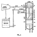
- FIG. 1 shows a nuclear power generating system that includes a simplified boiling water reactor 30 according to one embodiment of the invention.
- Boiling water reactor 30 has a steam outlet to a turbine-generator 40.
- Turbine-generator 40 generates electrical power and has an outlet for exhaust steam to a condenser 42.
- Condenser 42 condenses the exhaust steam to condensate and has a condensate outlet to the suction of condensate pump 51.
- Condensate pump 51 boosts the pressure of the condensate to the inlet pressure of feed-water pump 52.
- Feedwater pump 52 boosts the pressure of the condensate to a level exceeding the pressure interior of the reactor 30.
- the resultant discharged and pressurized condensate is now feedwater. This feedwater enters the interior of the reactor vessel through a sparger 54 inside nuclear reactor 30.
- Reactor 30 includes a reactor vessel 38 which houses a reactor core 36, a steam separator 34, and a steam dryer 32.
- Reactor core 36 heats water to generate a two-phase steam/water mixture.
- the two-phase mixture exits the reactor core from a core shroud head 33 immediately overlying core 36.
- the two-phase steam/water mixture is conducted through standpipes 37 mounted on the top of the core shroud head 33 to steam separator 34.
- Wet separated steam flows through steam dryer 32 to turbine-generator 40.
- Separated saturated water is discharged internally within the reactor vessel and flows into the reactor downcomer region 28.
- the discharged saturated water coolant undergoes mixing with the cooler feedwater being returned to the reactor at sparger 54.
- the two-phase steam/water mixture then passes upwardly through steam standpipes 37.
- the steam/water mixture encounters the steam separators 34. Water is rejected from the mixture at the steam separators (while the steam is channeled upwardly to thence flow through the dryers 32 and out the steam outlet 22).
- the rejected water flows over the top of the shroud tank 60. This rejected water then flows in the interstitial volume between the shroud tank 60 and the sidewall of the reactor vessel 30 at downcomer region 28. Once the water has traversed the downcomer region 28, the water returns to the bottom of the reactor vessel and the circulation of the coolant interior of the reactor is endlessly repeated.
- the hot two-phase mixture is conducted from the core upper plenum 31 to the steam separator 34 by a plurality of standpipes 37.
- the reactor vessel 38 includes a volume of water 82 at 546°F and 1020 psia in the region surrounding the steam separator standpipes. This coolant inventory region typically extends at least 20 feet above the reactor core shroud head 33 in a natural circulation boiling water reactor.
- a suppression pool (not shown) will be employed for exhaust and condensation of the steam flashing from the reactor.
- Shroud tank 60 circumscribes standpipes 37 and is disposed between separator assembly 34 at the upper end and the shroud head 33 at the lower end.
- Shroud tank 60 has an open top and closed bottom and a plurality of drain holes 62 at the bottom.
- the drain holes 62 are preferably disposed around the periphery of shroud tank wall near the tank bottom.
- the standpipes 37 extend completely through the shroud tank bottom and out and above the open top. These standpipes communicate steam/water mixture through the shroud tank without allowing mixing with the fluid in the shroud tank.
- Shroud tank 60 has an inlet fill pipe 66.
- Inlet fill pipe 66 receives cold coolant from feedwater pump 52.
- the temperature of feedwater supplied to reactor 30 is typically less than 546°F, typically by a margin of at least 120°F.
- feedwater heating is typically undertaken on the feedwater after is discharge from feedpump 52 and prior to its injection into reactor 30.
- the temperature of feedwater passing through feedpump 52 is typically 285°F.
- shroud tank 60 contains a volume of cold coolant relative to the otherwise hot, saturated water than would be contained in the same region in a conventional boiling water reaction.
- FIG 2 is an enlarged detailed cross-sectional diagram of a boiling water nuclear reactor 2 having a shroud tank disposed therein according to invention.
- the reactor 2 includes a reactor core 36 and core upper plenum 31.
- a shroud head 33 receives the two-phase steam/water mixture at the core outlet and transports the mixture to a group of standpipes 37 whereupon the mixture ultimately flows to steam separators 34.
- Steam separators 34 discharge wet steam to steam dryers 32 which have an ultimate output to steam nozzle 22 which connects reactor 2 to turbine-generator 40 through main steam line 24. (See Figure 1).
- Feedwater is supplied to the reactor vessel 2 through sparger 54. Hot, saturated coolant is discharged by steam separator assembly into downcomer region 28. The discharged feedwater mixes with the hot coolant entering into downcomer 28 and by natural circulation re-enters reactor core 36. Reactor core 36 heats the coolant to a two-phase steam/water mixture and the standpipes 37 conduct the two-phase mixture to steam separators 34 endlessly repeating the cycle.
- Shroud tank 60 circumscribes standpipes 37 and has an open top beyond which the standpipes extend.
- the bottom of shroud tank 60 is substantially closed by shroud head 33.
- a plurality of drain orifices or holes 62 are disposed about the periphery of shroud tank 60 near its bottom.
- the plurality of drain holes 62 are sized to enable fairly rapid draining of shroud tank 60 during a LOCA. As previously set forth, during such a casualty the water level in the reactor will drop below the level of the top rim of shroud tank 60.
- the drain holes 62 are located to permit the cold coolant water contained within the shroud tank to drain into the downcomer region radially and externally through the shroud tank wall.
- Fill pipe 66 supplies cold coolant to the interior of shroud tank 60.
- Fill pipe 66 extends through the reactor pressure vessel 38.
- Fill pipe 66 is shown extending downward into the very bottom of shroud tank 60.
- the fill pipe 66 discharges cold coolant toward the bottom of shroud tank 60.
- Figure 2 will be used to describe normal operation.
- Figure 3 will set forth operation during a LOCA.
- the invention has the added advantage that the coolant injection system used to inject coolant into the shroud tank need not be a safety grade system.
- the reactor undergoes a rapid depressurization.
- the coolant level inside the reactor will drop because of flashing and boil-off of steam from the hot coolant inventory.
- Water from the downcomer region will flow into the core to take the place of water flashed to steam. Operating level of the reactor water will fall.
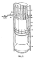
- FIG. 3 is an extreme example.
- the level of the water in the reactor is illustrated to have fallen below the level of the shroud tank bottom. This enables the flow from the drain holes 62 to be more clearly illustrated. It is important to realize, however, that flow of coolant for covering of the core begins long before the level illustrated in Figure 3 is reached.
- shroud tank 60 Because the contents of shroud tank 60 are relatively cold, this fluid will not undergo flashing to the same extent as does the hot coolant inventory. As a result, several significant benefits are achieved. First, the amount of reactor coolant lost during depressurization is reduced. More residual coolant is therefore available to prevent core uncovery or to minimize the duration of core uncovery during a LOCA. Secondly, depressurization may occur more rapidly because the total quantities of flashed steam released are minimized. Further, since the amount of steam released from the reactor is reduced, the design requirements for the containment system to handle the steam and energy quantities involved in depressurization may also be reduced.
- Figure 3 is a stylized pictorial illustration of the invention in operation during a LOCA.
- the level of hot coolant inventory in the reactor pressure vessel has fallen below the level of the orifices or holes contained around the bottom of the shroud tank.
- cold water inventory outflows from the shroud tank into the downcomer region of the reactor pressure vessel.
- the invention By placing the shroud tank inside the reactor vessel for operation during a LOCA, the invention avoids, or at least minimizes, the cost of constructing and operating an independent external source of emergency coolant outside the reactor vessel. It can also be seen that the invention is "passive", i.e., operates without activating any switches, pumps, or power supplies following a LOCA.
- a plurality of fill pipes may be provided to inject coolant into the shroud tank during normal operation.
- heat transfer barriers may be provided to prevent heat transfer from the standpipes to the contents of the shroud tank. These heat transfer barriers may be in the form of insulation applied to the standpipes, either internally or externally. Similarly, barriers to heat transfer may be applied to the core shroud head. As another alternative, the shroud tank itself may be insulated. As another alternative for minimizing undesirable heat transfer, the shroud tank, the standpipes, and the core shroud head or other portions of the reactor pressure vessel may be composed of materials having a relatively poor thermal conductivity
- a plurality of shroud tanks may be utilized.
- the shroud tanks may be coaxially configured about the reactor's vertical axis.
- the tank height is highest for the innermost shroud tank and is progressively lower for each tank disposed radially outward.
- the purpose for this configuration is to facilitate the lateral outflow of liquid discharged from the steam separators assembly.
- This particular embodiment would permit conventional water level "crowning" problems to be kept within acceptable limits.
- the size, location and number of drain holes might be substantially different amongst the various shroud tanks depending on design requirements.
- a valving system may be substituted for or added to the holes for permitting outflow of cold water coolant during a LOCA.
- the valves prevent the outflow of cold water coolant from the shroud tank until the pressure in the reactor vessel falls below a predetermined pressure.
- This predetermined pressure could be, for example, the pressure differential present when the reactor coolant level falls below the holes near the bottom of the shroud tank.
- shroud tank may be filled by a dedicated coolant pump and/or source of condensate external to the reactor vessel, the existing feedwater inlet may be used given the low rate of coolant injection required for the shroud tank.
- the invention is not limited in its application to a simplified boiling water reactor or a naturally cooled or natural circulation boiling water reactor.
- the invention may be used with systems other than the gravity-driven cooling suppression pool.
Landscapes
- Physics & Mathematics (AREA)
- Engineering & Computer Science (AREA)
- Plasma & Fusion (AREA)
- General Engineering & Computer Science (AREA)
- High Energy & Nuclear Physics (AREA)
- Structure Of Emergency Protection For Nuclear Reactors (AREA)
Applications Claiming Priority (2)
| Application Number | Priority Date | Filing Date | Title |
|---|---|---|---|
| US07/153,163 US4812286A (en) | 1988-02-08 | 1988-02-08 | Shroud tank and fill pipe for a boiling water nuclear reactor |
| US153163 | 1988-02-08 |
Publications (1)
| Publication Number | Publication Date |
|---|---|
| EP0332817A1 true EP0332817A1 (fr) | 1989-09-20 |
Family
ID=22546028
Family Applications (1)
| Application Number | Title | Priority Date | Filing Date |
|---|---|---|---|
| EP89101114A Withdrawn EP0332817A1 (fr) | 1988-02-08 | 1989-01-23 | Enveloppe et tube alimentateur pour un réacteur à eau bouillante |
Country Status (3)
| Country | Link |
|---|---|
| US (1) | US4812286A (fr) |
| EP (1) | EP0332817A1 (fr) |
| JP (1) | JPH0690302B2 (fr) |
Families Citing this family (9)
| Publication number | Priority date | Publication date | Assignee | Title |
|---|---|---|---|---|
| US5063020A (en) * | 1990-05-29 | 1991-11-05 | General Electric Company | Steam-water separating construction for boiling water nuclear reactors |
| US5076999A (en) * | 1990-10-10 | 1991-12-31 | The United States Of America As Represented By The United States Department Of Energy | Passive decay heat removal system for water-cooled nuclear reactors |
| US5245643A (en) * | 1992-03-16 | 1993-09-14 | General Electric Company | Top filled water regions overlying part length fuel rods |
| JP4568238B2 (ja) * | 2006-02-28 | 2010-10-27 | 日立Geニュークリア・エナジー株式会社 | 自然循環式沸騰水型原子炉 |
| JP4851811B2 (ja) * | 2006-02-28 | 2012-01-11 | 日立Geニュークリア・エナジー株式会社 | 自然循環式沸騰水型原子炉およびその取り扱い方法 |
| US8532245B2 (en) * | 2008-12-17 | 2013-09-10 | Westinghouse Electric Company Llc | Core shroud corner joints |
| US11935663B2 (en) | 2012-05-21 | 2024-03-19 | Smr Inventec, Llc | Control rod drive system for nuclear reactor |
| US9773576B2 (en) * | 2013-02-27 | 2017-09-26 | Smr Inventec, Llc | Nuclear reactor shroud |
| US11139087B2 (en) | 2019-04-11 | 2021-10-05 | Ge-Hitachi Nuclear Energy Americas Llc | Use of isolation condenser and/or feedwater to limit core flow, core power, and pressure in a boiling water reactor |
Citations (5)
| Publication number | Priority date | Publication date | Assignee | Title |
|---|---|---|---|---|
| GB1119469A (en) * | 1966-06-14 | 1968-07-10 | Euratom | Nuclear reactor cooling duct or pressure tube with solid internal insulation |
| US4064002A (en) * | 1973-07-31 | 1977-12-20 | Westinghouse Electric Corporation | Emergency core cooling system for a nuclear reactor |
| US4363780A (en) * | 1979-12-17 | 1982-12-14 | Ab Asea-Atom | Boiling reactor |
| DE3241051A1 (de) * | 1982-11-06 | 1984-05-10 | Brown Boveri Reaktor GmbH, 6800 Mannheim | Druckwasserreaktor mit einem reaktordruckbehaelter |
| EP0241345A1 (fr) * | 1986-04-01 | 1987-10-14 | Framatome | Réacteur nucléaire à guidage d'écoulement dans les équipements internes supérieurs |
Family Cites Families (9)
| Publication number | Priority date | Publication date | Assignee | Title |
|---|---|---|---|---|
| NL136725C (fr) * | 1962-07-31 | |||
| US3357891A (en) * | 1964-06-25 | 1967-12-12 | Atomenergi Ab | Nozzle device in flow tubes of a nuclear reactor of the boiling water type |
| US3392087A (en) * | 1964-08-08 | 1968-07-09 | Siemens Ag | Heterogeneous nuclear reactor of the pressure vessel type |
| US3401082A (en) * | 1966-05-24 | 1968-09-10 | Babcock & Wilcox Co | Integral steam generator and nuclear reactor combination |
| DE2217398A1 (de) * | 1972-04-11 | 1973-10-25 | Siemens Ag | Kernreaktor |
| DE2442500C2 (de) * | 1974-09-05 | 1984-06-28 | Interatom Internationale Atomreaktorbau Gmbh, 5060 Bergisch Gladbach | Druckwasserreaktor |
| US4759899A (en) * | 1984-08-29 | 1988-07-26 | Ga Technologies Inc. | Reactor with natural convection backup cooling system |
| US4702879A (en) * | 1986-06-11 | 1987-10-27 | Westinghouse Electric Corp. | Nuclear reactor with passive safety system |
| US4755348A (en) * | 1987-01-12 | 1988-07-05 | General Electric Company | Cooled water rod (LOCA conditions) |
-
1988
- 1988-02-08 US US07/153,163 patent/US4812286A/en not_active Expired - Fee Related
-
1989
- 1989-01-23 EP EP89101114A patent/EP0332817A1/fr not_active Withdrawn
- 1989-02-08 JP JP1027770A patent/JPH0690302B2/ja not_active Expired - Lifetime
Patent Citations (5)
| Publication number | Priority date | Publication date | Assignee | Title |
|---|---|---|---|---|
| GB1119469A (en) * | 1966-06-14 | 1968-07-10 | Euratom | Nuclear reactor cooling duct or pressure tube with solid internal insulation |
| US4064002A (en) * | 1973-07-31 | 1977-12-20 | Westinghouse Electric Corporation | Emergency core cooling system for a nuclear reactor |
| US4363780A (en) * | 1979-12-17 | 1982-12-14 | Ab Asea-Atom | Boiling reactor |
| DE3241051A1 (de) * | 1982-11-06 | 1984-05-10 | Brown Boveri Reaktor GmbH, 6800 Mannheim | Druckwasserreaktor mit einem reaktordruckbehaelter |
| EP0241345A1 (fr) * | 1986-04-01 | 1987-10-14 | Framatome | Réacteur nucléaire à guidage d'écoulement dans les équipements internes supérieurs |
Also Published As
| Publication number | Publication date |
|---|---|
| JPH01308997A (ja) | 1989-12-13 |
| JPH0690302B2 (ja) | 1994-11-14 |
| US4812286A (en) | 1989-03-14 |
Similar Documents
| Publication | Publication Date | Title |
|---|---|---|
| EP0232186B1 (fr) | Sureté passive pour réacteur nucléaire à eau pressurisée | |
| JP6243903B2 (ja) | モジュール式小型炉の安全系統 | |
| US6795518B1 (en) | Integral PWR with diverse emergency cooling and method of operating same | |
| JP4313204B2 (ja) | コンパクトな加圧水型原子炉 | |
| US4473528A (en) | Passive containment system | |
| EP2096644B1 (fr) | Système de refroidissement et de dépressurisation passif et centrale nucléaire à eau pressurisée | |
| US3859166A (en) | Combined storage tank and sump for nuclear reactor | |
| US4367194A (en) | Emergency core cooling system | |
| RU2078384C1 (ru) | Безопасная ядерная установка | |
| US4784824A (en) | Emergency cooling device for a pressurized water nuclear reactor | |
| KR100813939B1 (ko) | 안전보호용기를 구비한 일체형원자로의 피동형비상노심냉각설비 | |
| US20160148709A1 (en) | Stable startup system for nuclear reactor | |
| US5045274A (en) | Water cooled nuclear reactors | |
| US4812286A (en) | Shroud tank and fill pipe for a boiling water nuclear reactor | |
| CA1070860A (fr) | Eau de bassin pouvant ralentir un reacteur nucleaire | |
| US4810460A (en) | Nuclear boiling water reactor upper plenum with lateral throughpipes | |
| US3956063A (en) | Emergency core cooling system for a fast reactor | |
| JP2548838B2 (ja) | 加圧水型原子炉の炉心崩壊熱除去装置 | |
| JPS6375691A (ja) | 自然循環型原子炉 | |
| KR102072689B1 (ko) | 원자로 | |
| CN219202771U (zh) | 一种安全注入系统及核电系统 | |
| RU2025798C1 (ru) | Ядерный реактор с естественной циркуляцией теплоносителя | |
| Johnson et al. | Emergency core cooling system for a fast reactor | |
| Asahi et al. | Improvement of passive safety of reactors | |
| Vijuk et al. | Passive Safety Approach for The Advanced (W) 600 MWE PWR |
Legal Events
| Date | Code | Title | Description |
|---|---|---|---|
| PUAI | Public reference made under article 153(3) epc to a published international application that has entered the european phase |
Free format text: ORIGINAL CODE: 0009012 |
|
| AK | Designated contracting states |
Kind code of ref document: A1 Designated state(s): CH DE ES IT LI NL SE |
|
| 17P | Request for examination filed |
Effective date: 19900223 |
|
| STAA | Information on the status of an ep patent application or granted ep patent |
Free format text: STATUS: THE APPLICATION IS DEEMED TO BE WITHDRAWN |
|
| 18D | Application deemed to be withdrawn |
Effective date: 19920801 |