EP0332820B1 - Dispositif pour soutenir des personnes - Google Patents
Dispositif pour soutenir des personnes Download PDFInfo
- Publication number
- EP0332820B1 EP0332820B1 EP89101431A EP89101431A EP0332820B1 EP 0332820 B1 EP0332820 B1 EP 0332820B1 EP 89101431 A EP89101431 A EP 89101431A EP 89101431 A EP89101431 A EP 89101431A EP 0332820 B1 EP0332820 B1 EP 0332820B1
- Authority
- EP
- European Patent Office
- Prior art keywords
- support
- segment arc
- trunk
- lower legs
- pivot axis
- Prior art date
- Legal status (The legal status is an assumption and is not a legal conclusion. Google has not performed a legal analysis and makes no representation as to the accuracy of the status listed.)
- Expired - Lifetime
Links
Images


Classifications
-
- A—HUMAN NECESSITIES
- A61—MEDICAL OR VETERINARY SCIENCE; HYGIENE
- A61G—TRANSPORT, PERSONAL CONVEYANCES OR ACCOMMODATION SPECIALLY ADAPTED FOR PATIENTS OR DISABLED PERSONS; OPERATING TABLES OR CHAIRS; CHAIRS FOR DENTISTRY; FUNERAL DEVICES
- A61G7/00—Beds specially adapted for nursing; Devices for lifting patients or disabled persons
- A61G7/002—Beds specially adapted for nursing; Devices for lifting patients or disabled persons having adjustable mattress frame
- A61G7/015—Beds specially adapted for nursing; Devices for lifting patients or disabled persons having adjustable mattress frame divided into different adjustable sections, e.g. for Gatch position
-
- A—HUMAN NECESSITIES
- A47—FURNITURE; DOMESTIC ARTICLES OR APPLIANCES; COFFEE MILLS; SPICE MILLS; SUCTION CLEANERS IN GENERAL
- A47C—CHAIRS; SOFAS; BEDS
- A47C17/00—Sofas; Couches; Beds
- A47C17/04—Seating furniture, e.g. sofas, couches, settees, or the like, with movable parts changeable to beds; Chair beds
- A47C17/16—Seating furniture changeable to beds by tilting or pivoting the back-rest
- A47C17/162—Seating furniture changeable to beds by tilting or pivoting the back-rest with adjustable back-rest
-
- A—HUMAN NECESSITIES
- A47—FURNITURE; DOMESTIC ARTICLES OR APPLIANCES; COFFEE MILLS; SPICE MILLS; SUCTION CLEANERS IN GENERAL
- A47C—CHAIRS; SOFAS; BEDS
- A47C19/00—Bedsteads
- A47C19/04—Extensible bedsteads, e.g. with adjustment of length, width, height
- A47C19/045—Extensible bedsteads, e.g. with adjustment of length, width, height with entire frame height or inclination adjustments
-
- A—HUMAN NECESSITIES
- A47—FURNITURE; DOMESTIC ARTICLES OR APPLIANCES; COFFEE MILLS; SPICE MILLS; SUCTION CLEANERS IN GENERAL
- A47C—CHAIRS; SOFAS; BEDS
- A47C20/00—Head-, foot- or like rests for beds, sofas or the like
- A47C20/04—Head-, foot- or like rests for beds, sofas or the like with adjustable inclination
-
- A—HUMAN NECESSITIES
- A61—MEDICAL OR VETERINARY SCIENCE; HYGIENE
- A61G—TRANSPORT, PERSONAL CONVEYANCES OR ACCOMMODATION SPECIALLY ADAPTED FOR PATIENTS OR DISABLED PERSONS; OPERATING TABLES OR CHAIRS; CHAIRS FOR DENTISTRY; FUNERAL DEVICES
- A61G13/00—Operating tables; Auxiliary appliances therefor
- A61G13/02—Adjustable operating tables; Controls therefor
Definitions
- the invention relates to a device according to the preamble of the main claim.
- the device according to the invention can e.g. used in medicine as a so-called “therapy couch”.
- the device is also suitable for non-medical applications e.g. Suitable as a combination of reclining and seating furniture (such as a "TV armchair”).
- the segment arches make it possible for the lying surface to be pivoted very easily into any position, for example by gripping the lying surface on the head or lower leg support.
- two segment arches are used, which are arranged below the longitudinal edges of the lying surface in order to stabilize the device and to prevent the lying surface from tilting in the transverse direction.
- Mutual pivoting of the partial editions is also possible without difficulty.
- the upper body support can be pivoted about its pivot axis on the support elements.
- the buttocks / thigh support is also swiveled, since it is connected to the swiveling rocker via a swivel axis.
- the headrest and the lower leg rest can be pivoted so that the partial rest of the lying surface can be brought into the shape of an armchair. This facilitates the admission of the person to be treated.
- the reverse pivoting movements of the individual partial supports can also be carried out without difficulty.
- the segment arches are preferably pivotably mounted on rollers on the base frame.
- rollers or balls can also be attached to the segment arch, which run on a guide track on the base frame. After the segment arches and thus the lying surface or its partial supports have been pivoted into the desired position, it is desirable that they remain in this position.
- the segment arch can preferably be latched to the base frame.
- the segment arches can simply be stored on the rollers on the base frame. However, in order to prevent them from tipping sideways out of the underframe, the segment arches are preferably in contact on their inner circumference with counter-holding elements which are fastened to the underframe. They also have safety stops at their ends, which come into contact with the base frame when the segment arches are pivoted into the extreme positions. In this way, the tilting movement of the segment arches and thus also the lying surface is limited.
- actuators are preferably provided between the segment arches and the upper body support and between the rocker and the lower leg support. These limit the pivoting movement of the upper body support or lower leg support.
- These actuators can be cylinders, for example, in which a piston moves.
- the cylinders can be filled with gas or with a liquid medium.
- Valves are preferably provided in the piston which are opened when the respective partial contact surfaces are pivoted, so that the gas or the liquid medium can escape from one section of the cylinder into the other section. The valves are used to fix the partial contact surfaces in the desired position closed.
- the lower leg support is divided into two separately pivotable partial surfaces, as a result of which the lower legs can assume different angular positions.
- the head rest and the upper body rest are accommodated in a common frame in which the pivot axis of the support elements and the pivot axis of the head rest are mounted. Furthermore, the headrest can be pivoted relative to the upper body support. In this position, the head can be raised slightly in the lying position.
- the head rest can also be fixed with the help of actuators compared to the upper body rest.
- the headrest can also be swiveled downwards, for example when the person to be treated is placed on the lying surface in the prone position.
- the base frame can be mounted on a wheelchair chassis.
- the device can be easily moved.
- a patient can be placed or placed on the device in the hospital room and driven into the treatment room or one after the other into several treatment rooms.
- the base frame can of course also be permanently connected to the wheelchair chassis, so that the device serves primarily as a wheelchair, but which can easily be converted into a couch if required.
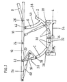
- the device shown in Fig. 1 shows a segment arch 2, which is mounted on a rectangular base frame 4.
- Two segment arches are usually provided. However, it is also possible to use a single segment arch that extends across the width of the base frame. On the other hand, three or more segment arches can also be used. Only the visible segment arch is shown in the drawing. The second segment arch is congruent behind the segment arch shown.
- One end of a support element 6 is fastened in the end region of each segment arch (on the right in the drawing).
- the connection of the support elements 6 to the lying surface consisting of head rest 8, upper body support 10, buttocks / thigh support 12 and lower leg support 14 is achieved in that the support elements 6 are articulated with their other end in the central region of the upper body support 10.
- the support elements 6 are connected to one another via a pivot axis 44 running transversely to the upper body support 10.
- a rocker 16 is articulated at one end 18. With the other end 20, each rocker is articulated on or in the vicinity of the pivot axis 22 between the buttock / thigh support 12 and the lower leg support 14.
- the buttocks / thigh support 12 is connected to the upper body support 10 via the pivot axis 24, and the upper body support 10 is connected to the head support 8 via the pivot axis 26.
- the individual partial contact surfaces are usually provided with pillows (not shown).
- the segment arches 2 are pivotally mounted on cross bars in the base frame 4.
- the rollers 28 are provided on the base frame 4, on which the outer circumference of the segment arches rests.
- the locking bars 30 are arranged between the segment arches in the transverse direction, which also serve as spacers between the segment arches and contribute to the stability of the device.
- a spring-operated latching lever 32 engages in the latching bars 30 and can be separated from the latching bars 30 with the aid of the latching release lever 34, so that the segment arch can be pivoted again.
- a slipping clutch can also be provided, which in the engaged position prevents the segmental arches 2 from being continuously pivoted relative to the base frame 4 and allows the pivoting when released.
- the segmental arch 2 is in contact on its inner circumference with counter-holding elements 36 which are fastened to the underframe 4.
- the counter-holding elements can be pins or cross bars which are fastened to the base frame 4.
- rollers are preferably provided, whereby the pivoting of the segment arches is facilitated.
- the segmental arch carries the safety stops 38, which come into contact with the base frame 4 when the segmental arches are pivoted into the extreme positions, for example by abutting the rollers 28.
- One or more actuators 40 can be provided between the segment arches 2 and the upper body support 10, as a result of which the pivoting movement of the upper body support 10 can be controlled.
- the actuator 40 preferably consists of a cylinder in which a piston slides.
- the cylinder cavity is with gas or filled with a liquid medium.
- a valve in the piston is opened so that the gas or the liquid medium can be displaced from one cylinder section to the next. If the valve is closed, the piston remains fixed in the desired position. If you want to swivel the upper body support again, you open the valve in the piston, which allows the gas or the liquid medium to flow back into the first cylinder section.
- a corresponding actuator 42 is also provided between the rocker 16 and the lower leg support 14, so that the lower leg support can be fixed in any angular position.
- a single actuator 42 is sufficient. If, however, the lower leg support 14 is divided into two separately pivotable partial surfaces, two actuators are expediently used.
- the actuators 40 and 42 can also be moved hydraulically.
- the headrest 8 and the upper body support 10 are accommodated in a common frame, which is indicated in the drawing by the fact that the upper body support 10 is extended to the right beyond the headrest.
- the pivot axis 44 of the support elements 6 and the pivot axis 26 of the headrest 8 are mounted in the common frame. It can be seen that the headrest 8 can be pivoted with respect to the upper body support 10, and an actuator can also be provided between the headrest and the frame of the upper body support.
- the headrest 10 is shown pivoted upwards in the drawing. However, it can also be swiveled downwards if the person to be treated lies prone.
- buttocks / thigh support 12 and the lower leg support 14 are each accommodated in a frame, the pivot axes 22 and 24 being mounted in the frame.
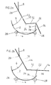
- the headrest 8 is in a substantially vertical position and is connected via the pivot axis 26 to the backrest 10 which is inclined at an angle of approximately 45 ° to the horizontal. This is connected via the pivot axis 44 to the support element 6 of the segment arch 2, which rests on the rollers 28 of the base frame 4.
- the upper body support is connected to the buttock / lower leg support 12 via the swivel axis 24 and forms an obtuse angle with it.
- the lower leg support 14 connected to the buttock / thigh support 12 via the pivot axis 22 is angled with respect to the buttock / thigh support 12.
- the pivot axis 22 is supported by the rocker 16, the lower end of which is pivotally attached to the pivot axis 18.
- the lower leg support 14 is raised horizontally.
- the buttocks / thigh support 12 is also horizontal, which is made possible by the fact that the rocker 16 shown in FIG. 2a in a vertical position is brought into a certain inclined position.
- the arrangement shown in Fig. 2b can also be tilted overall by pivoting the segment arch 2 on the rollers 28 so that the bearing surfaces 12 and 14 forming a plane point obliquely upwards and the buttocks at the pivot axis 24 occupies the lowest point.
- Fig. 2c shows an arrangement which is tilted in the manner of a rocking chair compared to the arrangement of Fig. 2b.
- the buttocks is in the lowest position (at 24), which is made possible by the fact that the rocker 16 has been pivoted inwards.
- the angle between the upper body support 10 and the support element 6 has become smaller.
- the lower leg support 14 is raised, whereby the lower legs and feet are in a comfortable rest position. In this position, the person can comfortably read or watch TV.
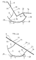
- FIG. 2d shows the device in a position in which all the support surfaces form a single inclined plane, the head support 8 possibly being raised. This position is particularly suitable for extensions (e.g. cervical vertebrae extensions or hip extensions).
- extensions e.g. cervical vertebrae extensions or hip extensions.
- FIG. 2e shows an elevated therapy position, which is used, for example, in treatments for the back or the spine.
- the person to be treated is in the prone position.
- Fig. 2f shows the normal resting or therapy position
- the head support 8 can also be raised if necessary.
- 2g shows a special treatment position, the treatment preferably being carried out in the prone position with the buttocks elevated.
Landscapes
- Health & Medical Sciences (AREA)
- General Health & Medical Sciences (AREA)
- Nursing (AREA)
- Veterinary Medicine (AREA)
- Animal Behavior & Ethology (AREA)
- Public Health (AREA)
- Life Sciences & Earth Sciences (AREA)
- Engineering & Computer Science (AREA)
- Biomedical Technology (AREA)
- Invalid Beds And Related Equipment (AREA)
- Accommodation For Nursing Or Treatment Tables (AREA)
- Refuse Collection And Transfer (AREA)
- Indicating And Signalling Devices For Elevators (AREA)
Claims (14)
caractérisé par le fait que
l'élément tournant présente un arc segmenté (2), au moins un élément de renfort (6) et au moins une bascule (16), par le fait que l'arc segmenté (2) est monté de manière pivotable sur l'infrastructure (4), par le fait que l'élément de renfort (6) est fixé par l'une de ses extrémités à une zone terminale de l'arc segmenté et par son autre extrémité dans la zone centrale de l'appui (10) pour le tronc et par le fait que la bascule (16) est articulée par l'une de ses extrémités (18) sur l'autre zone terminale de l'arc segmenté et par son autre extrémité (20) à l'axe de pivotement (22) ou à proximité de celui-ci entre le plan d'appui (12) pour le siège et les cuisses et le plan d'appui (14) pour les jambes.
Priority Applications (1)
| Application Number | Priority Date | Filing Date | Title |
|---|---|---|---|
| AT89101431T ATE78999T1 (de) | 1988-03-18 | 1989-01-27 | Geraet zum lagern von personen. |
Applications Claiming Priority (2)
| Application Number | Priority Date | Filing Date | Title |
|---|---|---|---|
| DE8803723U DE8803723U1 (de) | 1988-03-18 | 1988-03-18 | Gerät zum Lagern von Personen |
| DE8803723U | 1988-03-18 |
Publications (2)
| Publication Number | Publication Date |
|---|---|
| EP0332820A1 EP0332820A1 (fr) | 1989-09-20 |
| EP0332820B1 true EP0332820B1 (fr) | 1992-08-05 |
Family
ID=6822048
Family Applications (1)
| Application Number | Title | Priority Date | Filing Date |
|---|---|---|---|
| EP89101431A Expired - Lifetime EP0332820B1 (fr) | 1988-03-18 | 1989-01-27 | Dispositif pour soutenir des personnes |
Country Status (3)
| Country | Link |
|---|---|
| EP (1) | EP0332820B1 (fr) |
| AT (1) | ATE78999T1 (fr) |
| DE (2) | DE8803723U1 (fr) |
Families Citing this family (5)
| Publication number | Priority date | Publication date | Assignee | Title |
|---|---|---|---|---|
| DE29600903U1 (de) * | 1996-01-19 | 1996-03-28 | Schwind, Hubert, 89233 Neu-Ulm | Therapieliege |
| DE19615391A1 (de) * | 1996-04-18 | 1997-10-23 | Bavaria Patente & Lizenzen | Vorrichtung zur räumlich flexiblen Lagerung eines Probanden |
| US8615828B2 (en) * | 2003-02-10 | 2013-12-31 | Ferdinand Schermel | Multi-position reclining bed |
| CN108670354A (zh) * | 2018-05-28 | 2018-10-19 | 马千里 | 一种简易肾结石治疗床 |
| CN109966098A (zh) * | 2018-12-16 | 2019-07-05 | 杭州市第一人民医院 | 自调式前倾跪位接产装置 |
Family Cites Families (4)
| Publication number | Priority date | Publication date | Assignee | Title |
|---|---|---|---|---|
| US3149349A (en) * | 1961-08-30 | 1964-09-22 | Nelson Ted | Bed |
| US3797050A (en) * | 1972-08-10 | 1974-03-19 | Interroyal Corp | Shock and drainage mechanism |
| US4258445A (en) * | 1976-07-15 | 1981-03-31 | Zur Henry C | Beds and adjustable body supporting assemblies |
| DE3400637C2 (de) * | 1984-01-11 | 1986-06-19 | ROKADO Metall-Holz-Kunststoff GmbH & Co KG, 4755 Holzwickede | Vorrichtung zum Verstellen und Arretieren des Kopfteiles eines Bettrahmens |
-
1988
- 1988-03-18 DE DE8803723U patent/DE8803723U1/de not_active Expired
-
1989
- 1989-01-27 DE DE8989101431T patent/DE58901959D1/de not_active Expired - Lifetime
- 1989-01-27 EP EP89101431A patent/EP0332820B1/fr not_active Expired - Lifetime
- 1989-01-27 AT AT89101431T patent/ATE78999T1/de not_active IP Right Cessation
Also Published As
| Publication number | Publication date |
|---|---|
| DE8803723U1 (de) | 1988-05-11 |
| EP0332820A1 (fr) | 1989-09-20 |
| ATE78999T1 (de) | 1992-08-15 |
| DE58901959D1 (de) | 1992-09-10 |
Similar Documents
| Publication | Publication Date | Title |
|---|---|---|
| DE69826554T2 (de) | Lehnstuhl | |
| DE3615572C2 (de) | Krankenhausbett | |
| EP0030035B1 (fr) | Châlit | |
| DE2715739B2 (de) | Patientenstahl | |
| DE1541312A1 (de) | Mit Raedern versehener Invaliden- und Kombinationskrankenstuhl | |
| EP2175821A1 (fr) | Unité de redressement pour fauteuils roulants et chaises, en particulier chaises thérapeutiques | |
| DE68914491T2 (de) | Präsentierung eines Patienten. | |
| DE2517418A1 (de) | Rollstuhl | |
| DE3921384C1 (fr) | ||
| EP0332820A1 (fr) | Dispositif pour soutenir des personnes | |
| DE1162508B (de) | Krankenhaus-Drehbett | |
| DE69402978T2 (de) | Bett für intensivtherapie | |
| DE3805630C1 (en) | Wheelchair | |
| DE4422850A1 (de) | Verstellbarer Einlegerahmen für Bettgestelle | |
| DE2640985C3 (de) | Vorrichtung zum Überführen eines Patienten aus einer liegenden in eine sitzende Stellung und umgekehrt | |
| DE2747321B2 (de) | Transportable Behandlungsliege | |
| DE3206214C2 (fr) | ||
| EP1699319B1 (fr) | Meuble permettant de s' assoir ou de se coucher | |
| DE1941577C3 (de) | Einrichtung zum Ermöglichen oder Erleichtern des Sitzens für körperlich und geistig behinderte Personen | |
| DE1616167B1 (de) | Rollstuhl | |
| AT395529B (de) | Behandlungsliege, insbesondere massageliege | |
| DE3500212A1 (de) | Patientenrolley | |
| DE1256840B (de) | Gymnastik-Geraet zur Aufrechterhaltung und/oder Wiederherstellung physiologischer Koerperfunktionen, insbesondere zur Behandlung bzw. Verhuetung von Haltungsschaeden | |
| DE102004026632A1 (de) | Mechanik für Sitzliege | |
| DD283928A5 (de) | Rollstuhl zum heben und transport bewegungsunfaehiger patienten |
Legal Events
| Date | Code | Title | Description |
|---|---|---|---|
| PUAI | Public reference made under article 153(3) epc to a published international application that has entered the european phase |
Free format text: ORIGINAL CODE: 0009012 |
|
| AK | Designated contracting states |
Kind code of ref document: A1 Designated state(s): AT BE CH DE ES FR GB GR IT LI LU NL SE |
|
| 17P | Request for examination filed |
Effective date: 19890830 |
|
| RBV | Designated contracting states (corrected) |
Designated state(s): AT BE CH DE FR GB IT LI LU NL SE |
|
| RIN1 | Information on inventor provided before grant (corrected) |
Inventor name: SCHWIND, HUBERT |
|
| 17Q | First examination report despatched |
Effective date: 19910416 |
|
| GRAA | (expected) grant |
Free format text: ORIGINAL CODE: 0009210 |
|
| AK | Designated contracting states |
Kind code of ref document: B1 Designated state(s): AT BE CH DE FR GB IT LI LU NL SE |
|
| REF | Corresponds to: |
Ref document number: 78999 Country of ref document: AT Date of ref document: 19920815 Kind code of ref document: T |
|
| REF | Corresponds to: |
Ref document number: 58901959 Country of ref document: DE Date of ref document: 19920910 |
|
| ET | Fr: translation filed | ||
| ITF | It: translation for a ep patent filed | ||
| GBT | Gb: translation of ep patent filed (gb section 77(6)(a)/1977) | ||
| PGFP | Annual fee paid to national office [announced via postgrant information from national office to epo] |
Ref country code: SE Payment date: 19921123 Year of fee payment: 5 |
|
| PGFP | Annual fee paid to national office [announced via postgrant information from national office to epo] |
Ref country code: FR Payment date: 19921218 Year of fee payment: 5 |
|
| PGFP | Annual fee paid to national office [announced via postgrant information from national office to epo] |
Ref country code: GB Payment date: 19930112 Year of fee payment: 5 |
|
| PGFP | Annual fee paid to national office [announced via postgrant information from national office to epo] |
Ref country code: AT Payment date: 19930114 Year of fee payment: 5 |
|
| PGFP | Annual fee paid to national office [announced via postgrant information from national office to epo] |
Ref country code: DE Payment date: 19930119 Year of fee payment: 5 |
|
| PGFP | Annual fee paid to national office [announced via postgrant information from national office to epo] |
Ref country code: LU Payment date: 19930127 Year of fee payment: 5 |
|
| PGFP | Annual fee paid to national office [announced via postgrant information from national office to epo] |
Ref country code: NL Payment date: 19930131 Year of fee payment: 5 |
|
| PGFP | Annual fee paid to national office [announced via postgrant information from national office to epo] |
Ref country code: BE Payment date: 19930204 Year of fee payment: 5 |
|
| PGFP | Annual fee paid to national office [announced via postgrant information from national office to epo] |
Ref country code: CH Payment date: 19930217 Year of fee payment: 5 |
|
| EPTA | Lu: last paid annual fee | ||
| PLBE | No opposition filed within time limit |
Free format text: ORIGINAL CODE: 0009261 |
|
| STAA | Information on the status of an ep patent application or granted ep patent |
Free format text: STATUS: NO OPPOSITION FILED WITHIN TIME LIMIT |
|
| 26N | No opposition filed | ||
| PG25 | Lapsed in a contracting state [announced via postgrant information from national office to epo] |
Ref country code: LU Free format text: LAPSE BECAUSE OF NON-PAYMENT OF DUE FEES Effective date: 19940127 Ref country code: GB Effective date: 19940127 Ref country code: AT Effective date: 19940127 |
|
| PG25 | Lapsed in a contracting state [announced via postgrant information from national office to epo] |
Ref country code: SE Effective date: 19940128 |
|
| PG25 | Lapsed in a contracting state [announced via postgrant information from national office to epo] |
Ref country code: LI Effective date: 19940131 Ref country code: CH Effective date: 19940131 Ref country code: BE Effective date: 19940131 |
|
| BERE | Be: lapsed |
Owner name: SCHUPP G.M.B.H. & CO. Effective date: 19940131 |
|
| PG25 | Lapsed in a contracting state [announced via postgrant information from national office to epo] |
Ref country code: NL Effective date: 19940801 |
|
| NLV4 | Nl: lapsed or anulled due to non-payment of the annual fee | ||
| GBPC | Gb: european patent ceased through non-payment of renewal fee |
Effective date: 19940127 |
|
| PG25 | Lapsed in a contracting state [announced via postgrant information from national office to epo] |
Ref country code: FR Effective date: 19940930 |
|
| REG | Reference to a national code |
Ref country code: CH Ref legal event code: PL |
|
| PG25 | Lapsed in a contracting state [announced via postgrant information from national office to epo] |
Ref country code: DE Effective date: 19941001 |
|
| REG | Reference to a national code |
Ref country code: FR Ref legal event code: ST |
|
| EUG | Se: european patent has lapsed |
Ref document number: 89101431.8 Effective date: 19940810 |
|
| PG25 | Lapsed in a contracting state [announced via postgrant information from national office to epo] |
Ref country code: IT Free format text: LAPSE BECAUSE OF NON-PAYMENT OF DUE FEES;WARNING: LAPSES OF ITALIAN PATENTS WITH EFFECTIVE DATE BEFORE 2007 MAY HAVE OCCURRED AT ANY TIME BEFORE 2007. THE CORRECT EFFECTIVE DATE MAY BE DIFFERENT FROM THE ONE RECORDED. Effective date: 20050127 |