EP0333067A2 - Appareil de triage pour feuilles de papier ou similaires - Google Patents
Appareil de triage pour feuilles de papier ou similaires Download PDFInfo
- Publication number
- EP0333067A2 EP0333067A2 EP89104286A EP89104286A EP0333067A2 EP 0333067 A2 EP0333067 A2 EP 0333067A2 EP 89104286 A EP89104286 A EP 89104286A EP 89104286 A EP89104286 A EP 89104286A EP 0333067 A2 EP0333067 A2 EP 0333067A2
- Authority
- EP
- European Patent Office
- Prior art keywords
- sorting device
- switch
- storage compartment
- sheets
- belt
- Prior art date
- Legal status (The legal status is an assumption and is not a legal conclusion. Google has not performed a legal analysis and makes no representation as to the accuracy of the status listed.)
- Withdrawn
Links
Images

Classifications
-
- B—PERFORMING OPERATIONS; TRANSPORTING
- B65—CONVEYING; PACKING; STORING; HANDLING THIN OR FILAMENTARY MATERIAL
- B65H—HANDLING THIN OR FILAMENTARY MATERIAL, e.g. SHEETS, WEBS, CABLES
- B65H29/00—Delivering or advancing articles from machines; Advancing articles to or into piles
- B65H29/58—Article switches or diverters
- B65H29/60—Article switches or diverters diverting the stream into alternative paths
Definitions
- the invention relates to a sorting device for sheets of paper or the like according to the preamble of claim 1.
- Sorting devices for sheets are connected downstream of copying machines, data printers and similar devices in order to distribute the output sheets to the storage compartments controlled by switches.
- a sorting device of the type mentioned is known, in which the sheets are transported past the storage compartments along a conveyor track.
- a switch is assigned to each storage compartment, which can be swiveled into the conveying plane of the conveyor track in a controlled manner in order to deflect the sheet out of the conveying plane into the associated storage compartment.
- a control lever which strikes the switch and pivots it, is used for the controlled actuation of the switches. The lever sits on a plate which can be moved along the conveyor track in a controlled manner in order to actuate the selected switch.
- the sheet deflected by the switch is conveyed via a guide plate to the associated storage compartment, for which purpose a driven transport roller grasps the sheet on the guide plate.
- the guide plate and the transport roller are also mounted on the plate which can be moved along the conveyor track and which carries the lever which actuates the switches.
- the transport roller is driven by a gear the mechanism that moves the plate.
- a sorting device in which the sheets transported along a vertical conveying path reach the associated storage compartments by means of switches, the switches being able to be pivoted in a controlled manner into the conveying plane of the conveying path.
- the sheets deflected from the conveyor track go directly into the storage compartments. Since the sheets are only actively moved forward on the conveyor track, a complete ejection of the sheets into the storage compartments is not reliably guaranteed.
- the invention has for its object to provide a sorting device for sheets of paper or the like, which combines a quick control of the individual storage compartments with a reliable ejection of the sheets in the storage compartments in a simple manner.
- a separate guide plate with a driven transport roller is arranged between each switch and the associated storage compartment.
- the turnouts can therefore be controlled in any order, immediately one after the other, without having to move any actuating means from one turnout to the next controlled turnout in a time-consuming manner.
- the transport rollers of all storage compartments are driven in a particularly simple and inexpensive manner by means of a common belt.
- This belt runs freely past pulleys connected to the transport rollers, so that the transport rollers are normally not driven.
- the belt is only pressed into engagement with the pulley of the transport roller by a clutch wheel in order to drive it. In this way, only the transport roller of the selected storage compartment is driven by the belt.
- the drive of the transport rollers therefore requires little energy and generates few disturbing noises.
- the clutch wheels are preferably rotatably mounted on levers and can be moved into the coupling position by means of these levers, each controlled by an electromagnet.
- the lever supporting the clutch wheel also simultaneously actuates the associated switch.
- the turnout and the drive can thus be swiveled in via a single electromagnet the transport roller can be controlled.
- this lever can also actuate a hold-down device for the paper stack already deposited in the respective storage compartment in such a way that the hold-down device is lifted by the lever from the deposited sheet stack when the lever is pivoted into the engaging position, so that the next sheet fed is unimpeded can be placed on the stack. If the lever swings back again to put the switch out of operation and to disengage the drive of the transport roller, the lever releases the hold-down device so that it sits on the stack of sheets again and compresses it to save space.
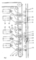
- the sheets output by a copying machine, a data printer or the like arrive via a paper guide (not shown) to a vertical conveyor track which consists of endlessly rotating driven conveyor belts 10 and conveyor rollers 12 which are flexibly supported on these.
- a vertical conveyor track which consists of endlessly rotating driven conveyor belts 10 and conveyor rollers 12 which are flexibly supported on these.
- drive rollers and deflection rollers of the conveyor belt 10 and the conveyor rollers 12 are mounted between side walls of the sorting device, not shown.
- the sheets are transported vertically downward between the conveyor belts 10 and the conveyor rollers 12.
- a plurality of storage compartments 14 are arranged one above the other, in which the sheets are stacked in a substantially horizontal manner.
- a switch 16 is assigned to each of the storage compartments.
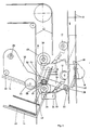
- the switches 16 are pivotally mounted between the side walls of the sorting device and each have a deflection surface 18. In the non-actuated position shown in FIG. 2, the switch is supported by its own weight and possibly supported by a spring in a position in which its deflection surface 18 is located behind the downward conveying run of the conveyor belts 10. In the operation described later, shown in Figure 3, the switch 16 is pivoted so that its deflecting surface 18 engages between the conveyor belt 10.
- a sheet running down the conveyor path is then deflected out of the conveying plane of the conveyor belts 10 by the deflection surface 18 of the switch 16 and reaches a guide plate 20 which is arranged between the switch 16 and the associated storage compartments 14 and is fastened to the side walls.
- the guide plates 20 are angled downward at their end facing the conveyor belt 10, so that they each form a guide funnel for the sheets running downward between the conveyor rollers 12.
- a metallic brush 24 bears against the continuous sheet from above in order to prevent electrostatic charging of the sheets.
- the sheet reaching the guide plate 20 from the switch 16 is grasped by a driven transport roller 26 which cooperates with the guide plate 20 and is mounted between the side walls and is ejected into the associated storage compartment 14.
- each storage compartment is assigned a lever 30 which is pivotally mounted on the outside of a side wall. The pivot point of the lever 30 is located at its end facing the electromagnet 28, so that the lever 30 bears under its own weight with a pin 32 on the armature of the respectively associated electromagnet 28.
- the lever 30 extends with an extension 34 of its free end up to the respectively associated switch 16. If the electromagnets 28 of the uncontrolled storage compartments 14 are not energized, their armature is in the retracted position, as shown in FIG upper electromagnet 28 is shown. The respectively associated lever 30 follows the movement of the armature and swivels downward into the position shown in FIG. 2, in which its extension 34 moves away from the switch 16.
- a storage compartment 14 of the sorting device is actuated by the copier, data printing or the like in order to deposit the sheet fed via the conveying path into this storage compartment 14, the electromagnet 24 assigned to this storage compartment 14 is excited and its armature is extended axially, as shown in FIG. 1 for the second electromagnet is shown from below.
- the electromagnet 28 pivots the lever 30 counterclockwise about the pivot point 33 via the pin 32 in the position shown in Figure 3.
- the lever 30 comes to rest with a roller 36 arranged on its extension 34 on a run-up surface 38 which is arranged on the outside of the side wall of the sorting device at the top of the switch 16. Due to the pressure of the roller 36 against the run-up surface 38, the switch 16 is pivoted into the actuated position shown in FIG. 3, in which it projects with its deflection surface 18 into the conveying plane of the conveyor track.
- a driven endlessly revolving belt 42 runs past the pulleys 40 at a small radial distance, so that it does not come into engagement with the pulleys 40 and does not drive these pulleys 40 and thus the transport rollers 26.
- a clutch wheel 44 is rotatably mounted on the levers 30 in the area of the belt 42. If the lever is in the downwardly pivoted position of FIG. 2 when the electromagnet 28 is not actuated, then its clutch wheel 44 is located on the side of the belt 42 facing away from the belt pulleys 40 at a short distance from this belt 42. The belt 42 therefore does not come with the clutch wheel 44 still in contact with the pulley 40, so that the belt 42 passes through without energy consumption and noise.
- a hold-down 48 sits on the stack 46 of sheets stored in the storage compartment 14 in order to press the stack down in a space-saving manner.
- the hold-down 48 is essentially in the form of a toothed plate standing upright on the stack 46.
- the hold-down 48 is slidably guided between the side walls perpendicular to the stack surface.
- an axis 50 is rotatably mounted in the hold-down device.
- the axle 50 is guided with its two ends through elongated holes 52 in the side walls, which extend in the direction of movement of the hold-down device.
- a pinion 54 is seated on both ends of the axis 50 in a rotationally fixed manner.
- the pinions 54 each mesh with a toothed rack 56 which runs parallel to the elongated hole 52 and is fastened to the side wall Racks 56 running pinion 54 ensures that the hold-down 48 can only raise and lower exactly in parallel.
- the levers 30 there is a tab 58 bent from the pivoting plane, which abuts the end of the axis 50 from below. If the lever 30 is in the lowered position shown in FIG. 2, the hold-down 48 with its axis 50 on the tab 58 can move downward due to its own weight until it rests on the stack 46 in the storage compartment 14. If a storage compartment 14 is actuated and the associated lever 30 is pivoted up into the position shown in FIG. 3 by the electromagnet 28, the lever 30 takes the hold-down device 48 with its tab 58 and lifts it off the stack 46. The sheet fed via the controlled switch 16 can thus be ejected into the storage compartment 14 without hindrance by the hold-down device 48. If the lever 30 then pivots downward again, the hold-down device 48 lowers on the fed sheet and presses it down onto the stack 46.
Landscapes
- Engineering & Computer Science (AREA)
- Mechanical Engineering (AREA)
- Pile Receivers (AREA)
- Delivering By Means Of Belts And Rollers (AREA)
- Collation Of Sheets And Webs (AREA)
- Sorting Of Articles (AREA)
- Handling Of Cut Paper (AREA)
- Separation, Sorting, Adjustment, Or Bending Of Sheets To Be Conveyed (AREA)
Applications Claiming Priority (2)
| Application Number | Priority Date | Filing Date | Title |
|---|---|---|---|
| DE3808332A DE3808332A1 (de) | 1988-03-12 | 1988-03-12 | Sortiergeraet fuer blaetter aus papier oder dergleichen |
| DE3808332 | 1988-03-12 |
Publications (2)
| Publication Number | Publication Date |
|---|---|
| EP0333067A2 true EP0333067A2 (fr) | 1989-09-20 |
| EP0333067A3 EP0333067A3 (fr) | 1990-08-16 |
Family
ID=6349604
Family Applications (1)
| Application Number | Title | Priority Date | Filing Date |
|---|---|---|---|
| EP89104286A Withdrawn EP0333067A3 (fr) | 1988-03-12 | 1989-03-10 | Appareil de triage pour feuilles de papier ou similaires |
Country Status (4)
| Country | Link |
|---|---|
| US (1) | US4986530A (fr) |
| EP (1) | EP0333067A3 (fr) |
| JP (1) | JPH01275369A (fr) |
| DE (1) | DE3808332A1 (fr) |
Cited By (1)
| Publication number | Priority date | Publication date | Assignee | Title |
|---|---|---|---|---|
| EP0436404A3 (en) * | 1989-12-12 | 1992-02-12 | Auto- Stamp Institute Incorporated | Paper conveyor |
Families Citing this family (5)
| Publication number | Priority date | Publication date | Assignee | Title |
|---|---|---|---|---|
| US6454476B1 (en) | 1999-04-14 | 2002-09-24 | Hewlett-Packard Company | Apparatus and method for picking and feeding print media sheets |
| US9434875B1 (en) | 2014-12-16 | 2016-09-06 | Carbo Ceramics Inc. | Electrically-conductive proppant and methods for making and using same |
| WO2014107608A1 (fr) | 2013-01-04 | 2014-07-10 | Carbo Ceramics Inc. | Agent de soutènement électroconducteur et procédés de détection, localisation et caractérisation de l'agent de soutènement électroconducteur |
| US11008505B2 (en) | 2013-01-04 | 2021-05-18 | Carbo Ceramics Inc. | Electrically conductive proppant |
| US9551210B2 (en) | 2014-08-15 | 2017-01-24 | Carbo Ceramics Inc. | Systems and methods for removal of electromagnetic dispersion and attenuation for imaging of proppant in an induced fracture |
Family Cites Families (13)
| Publication number | Priority date | Publication date | Assignee | Title |
|---|---|---|---|---|
| US3937459A (en) * | 1974-09-16 | 1976-02-10 | Keith B. Stewart | Sorting machine |
| DE2627502A1 (de) * | 1976-06-18 | 1977-12-29 | Blainey Stewart Keith | Blattsortiermaschine |
| US4068837A (en) * | 1976-09-29 | 1978-01-17 | International Business Machines Corporation | Paper hold-down device for collector |
| DE2939941C2 (de) * | 1978-10-06 | 1986-09-25 | Canon K.K., Tokio/Tokyo | Blattsortier- und -stapeleinrichtung |
| DE2926115C2 (de) * | 1979-06-28 | 1981-10-08 | Mathias Bäuerle GmbH, 7742 St Georgen | Vorrichtung zum Verteilen von Bogen in Sammelfächer |
| US4317203A (en) * | 1979-09-19 | 1982-02-23 | International Business Machines Corporation | Collator error recovery |
| US4349190A (en) * | 1979-09-29 | 1982-09-14 | Ricoh Co., Ltd. | Sheet classifying system having deflecting device |
| JPS5733151A (en) * | 1980-07-31 | 1982-02-23 | Olympus Optical Co Ltd | Collator |
| US4494748A (en) * | 1981-12-30 | 1985-01-22 | Olympus Optical Co., Ltd. | Collator |
| JPS61101361A (ja) * | 1984-10-20 | 1986-05-20 | Fuji Photo Film Co Ltd | シ−ト選別搬送装置 |
| GB2171396B (en) * | 1985-02-23 | 1988-11-23 | Unisys Corp | Self-aligning document stacker |
| US4691914A (en) * | 1986-01-21 | 1987-09-08 | Gradco Systems, Inc. | Sheet receiver |
| US4819931A (en) * | 1986-09-09 | 1989-04-11 | Ikegami Tsushinki Co., Ltd. | Sorting apparatus |
-
1988
- 1988-03-12 DE DE3808332A patent/DE3808332A1/de active Granted
-
1989
- 1989-03-07 JP JP1053067A patent/JPH01275369A/ja active Pending
- 1989-03-10 EP EP89104286A patent/EP0333067A3/fr not_active Withdrawn
- 1989-03-10 US US07/321,858 patent/US4986530A/en not_active Expired - Fee Related
Cited By (2)
| Publication number | Priority date | Publication date | Assignee | Title |
|---|---|---|---|---|
| EP0436404A3 (en) * | 1989-12-12 | 1992-02-12 | Auto- Stamp Institute Incorporated | Paper conveyor |
| US5183249A (en) * | 1989-12-12 | 1993-02-02 | Auto-Stamp Institute Inc. | Paper conveyor |
Also Published As
| Publication number | Publication date |
|---|---|
| JPH01275369A (ja) | 1989-11-06 |
| DE3808332A1 (de) | 1989-09-21 |
| EP0333067A3 (fr) | 1990-08-16 |
| US4986530A (en) | 1991-01-22 |
| DE3808332C2 (fr) | 1991-01-03 |
Similar Documents
| Publication | Publication Date | Title |
|---|---|---|
| DE3303786C2 (de) | Automatische Banknotenannahme- und -ausgabevorrichtung | |
| DE3700959C2 (de) | Bogensammelvorrichtung | |
| DE3420336C2 (de) | Papierblatt-Ablagevorrichtung | |
| CH643490A5 (de) | Vorrichtung zum zufuehren und ablegen von einzelblaettern fuer eine schreibende buero- oder datenverarbeitungsmaschine. | |
| DE2711173B2 (de) | Einrichtung an einer schreibenden oder druckenden Büromaschine zum Beschicken derselben mit Blättern | |
| DE4042358C2 (de) | Sortiergerät zur Ablage von blattförmigen Aufzeichnungsträgern | |
| DE1266627B (de) | Papierzufuehrungseinrichtung | |
| DE3044476C2 (fr) | ||
| DE1938556A1 (de) | Vorrichtung zum Ordnen bzw. Ausrichten von Blaettern | |
| EP0213429B1 (fr) | Dispositif d'empilage de bande de papier plié | |
| DE3036674C2 (de) | Sortierer | |
| DE3839304C2 (fr) | ||
| EP0333067A2 (fr) | Appareil de triage pour feuilles de papier ou similaires | |
| DE2344813A1 (de) | Vorrichtung zum ablegen von blaettern | |
| DE3917373A1 (de) | Vorrichtung zum ablegen von blaettern | |
| DE3808333A1 (de) | Sortiergeraet fuer blaetter aus papier oder dergleichen | |
| EP0000366B1 (fr) | Dispositif d'alimentation en feuilles | |
| EP0195915A2 (fr) | Dispositif pour empiler des bandes de feuilles pliées en accordéon | |
| DE1207876B (de) | Vertikal beweglich angeordneter Stapler fuer flache Sendungen mit Einrichtung zur Entnahme des gebildeten Stapels | |
| DE3031869C2 (de) | Vorrichtung zum Zuführen von Einzelblättern zur Schreibstation einer schreibenden Büro- oder Datenverarbeitungsmaschine und zum Ablegen der von der Schreibstation kommenden Einzelblätter | |
| DE2039143C3 (fr) | ||
| EP1218271B1 (fr) | Dispositif pour tourner une pile de papier | |
| DE2724284A1 (de) | Beladevorrichtung | |
| CH668407A5 (de) | Vorrichtung zum entstapeln plattenfoermiger teile. | |
| CH668409A5 (de) | Vorrichtung zum aussondern nicht verwendbarer plattenfoermiger teile. |
Legal Events
| Date | Code | Title | Description |
|---|---|---|---|
| PUAI | Public reference made under article 153(3) epc to a published international application that has entered the european phase |
Free format text: ORIGINAL CODE: 0009012 |
|
| AK | Designated contracting states |
Kind code of ref document: A2 Designated state(s): CH DE FR GB IT LI |
|
| PUAL | Search report despatched |
Free format text: ORIGINAL CODE: 0009013 |
|
| AK | Designated contracting states |
Kind code of ref document: A3 Designated state(s): CH DE FR GB IT LI |
|
| STAA | Information on the status of an ep patent application or granted ep patent |
Free format text: STATUS: THE APPLICATION IS DEEMED TO BE WITHDRAWN |
|
| 18D | Application deemed to be withdrawn |
Effective date: 19910219 |