EP0333088B2 - Soupape de commande - Google Patents
Soupape de commande Download PDFInfo
- Publication number
- EP0333088B2 EP0333088B2 EP89104378A EP89104378A EP0333088B2 EP 0333088 B2 EP0333088 B2 EP 0333088B2 EP 89104378 A EP89104378 A EP 89104378A EP 89104378 A EP89104378 A EP 89104378A EP 0333088 B2 EP0333088 B2 EP 0333088B2
- Authority
- EP
- European Patent Office
- Prior art keywords
- valve element
- housing
- control valve
- valve
- pressure
- Prior art date
- Legal status (The legal status is an assumption and is not a legal conclusion. Google has not performed a legal analysis and makes no representation as to the accuracy of the status listed.)
- Expired - Lifetime
Links
Images


Classifications
-
- F—MECHANICAL ENGINEERING; LIGHTING; HEATING; WEAPONS; BLASTING
- F16—ENGINEERING ELEMENTS AND UNITS; GENERAL MEASURES FOR PRODUCING AND MAINTAINING EFFECTIVE FUNCTIONING OF MACHINES OR INSTALLATIONS; THERMAL INSULATION IN GENERAL
- F16K—VALVES; TAPS; COCKS; ACTUATING-FLOATS; DEVICES FOR VENTING OR AERATING
- F16K11/00—Multiple-way valves, e.g. mixing valves; Pipe fittings incorporating such valves
- F16K11/02—Multiple-way valves, e.g. mixing valves; Pipe fittings incorporating such valves with all movable sealing faces moving as one unit
- F16K11/06—Multiple-way valves, e.g. mixing valves; Pipe fittings incorporating such valves with all movable sealing faces moving as one unit comprising only sliding valves, i.e. sliding closure elements
- F16K11/072—Multiple-way valves, e.g. mixing valves; Pipe fittings incorporating such valves with all movable sealing faces moving as one unit comprising only sliding valves, i.e. sliding closure elements with pivoted closure members
- F16K11/074—Multiple-way valves, e.g. mixing valves; Pipe fittings incorporating such valves with all movable sealing faces moving as one unit comprising only sliding valves, i.e. sliding closure elements with pivoted closure members with flat sealing faces
-
- B—PERFORMING OPERATIONS; TRANSPORTING
- B60—VEHICLES IN GENERAL
- B60T—VEHICLE BRAKE CONTROL SYSTEMS OR PARTS THEREOF; BRAKE CONTROL SYSTEMS OR PARTS THEREOF, IN GENERAL; ARRANGEMENT OF BRAKING ELEMENTS ON VEHICLES IN GENERAL; PORTABLE DEVICES FOR PREVENTING UNWANTED MOVEMENT OF VEHICLES; VEHICLE MODIFICATIONS TO FACILITATE COOLING OF BRAKES
- B60T17/00—Component parts, details, or accessories of power brake systems not covered by groups B60T8/00, B60T13/00 or B60T15/00, or presenting other characteristic features
- B60T17/04—Arrangements of piping, valves in the piping, e.g. cut-off valves, couplings or air hoses
Definitions
- a first invention relates, according to the preamble of claim 1, to a switching valve for controlling, in particular, pneumatic pressure media, consisting of a housing with an input channel to which system pressure can be applied and at least one output channel and with two disk-shaped arranged in a housing chamber and sealing in the operating state under a pressing force
- Valve elements lying one on top of the other preferably made of ceramic material, the first valve element being mounted stationary in the housing chamber and the second valve element being rotatably arranged in the housing chamber between at least two switching positions in such a way that the input and output channels can be connected to one another or in pairs or can be blocked against one another, wherein each input and output channel of the housing merges into a through opening of the first, stationary valve element and the connection of at least two of the channels of the housing It is carried out via the second valve element, which covers the through openings of the first valve element and at least in pairs, depending on the switching position. It is essential here that all through openings of the stationary valve element which are directly connected to the housing channels are covered by the
- Such a switching valve is known from DE-A-3539316.
- the disk-shaped valve elements of such switching valves have extremely smooth surfaces with which they are in intimate contact with one another, lying on top of one another. As a result, the valve elements are held together due to the adhesive forces that occur, which results in a sealing effect between the valve elements, but these are nevertheless rotatable and / or displaceable relative to one another. In order to push the valve elements apart by the system pressure, e.g.
- the known valve provides that the valve elements are pressed against one another with a certain contact pressure, and although a mechanical pre-tension is used here, for example generated by rubber-elastic pressure or sealing elements. This means that the valve elements lying on top of one another as a “package unit” are pressed against one another with a force determined by the pressure elements.
- a mechanical pre-tension for example generated by rubber-elastic pressure or sealing elements.
- the valve elements lying on top of one another as a “package unit” are pressed against one another with a force determined by the pressure elements.
- the mechanical pressure and sealing elements are more complex than 6 bar and the resulting separation forces are difficult to control.
- the amount of contact pressure can already be set in the known valve, but this setting must be made manually on the basis of the pressure values to be expected.
- the disadvantage here is that system pressure changes, e.g. pressure peaks occurring during the operation of the switching valve can not be taken into account in the setting, which can consequently lead to sealing problems due to a gap occurring between the valve elements
- a rotary slide valve not of the generic type in connection with a compressed air braking device, a rotary slide valve not of the generic type is known in that it has a disk-shaped valve element (rotary slide valve) which rests directly on the inner surface of a housing plate (called a "valve seat"), but at the same time not all channels of the housing plate - which in principle forms a "stationary valve element” - are covered. Rather, the pressure input channel "outside" of the rotary valve opens into the interior of the housing, which is thereby constantly under pressure, as a result of which the rotary valve is to be held in contact with the housing plate by pressurization. However, as a result, the interior of the housing is also part of the flow path in certain switching positions, which can lead to flow-related (dynamic) pressure changes.
- DE-A-32 40 832 describes a likewise non-generic changeover valve with two disk-shaped ceramic valve elements, namely a stationary disk and a rotatable disk.
- a connection piece which is to be connected to a pressure line, opens directly into the interior of the housing in an area "above” the movable valve disk. The interior therefore also forms part of the flow path here.
- the invention is based "Addition X" the task of improving the known switching valve of the generic type so that the amount of the pressing force pressing the valve elements against each other automatically adapts to the respective system pressure and that mechanical pressure elements i.w. can spare.
- the second, movable valve element has at least one annular segment segment of this type Has passage opening, which in each switching position at least partially covers the passage opening of the first valve element connected to the input channel and in at least one of the switching positions additionally at least one of the other passage openings, so that in order to generate the contact pressure, the second valve element on its surface facing away from the first valve element in each Switch position with the system pressure of the pressure medium prevailing in the input channel.
- a through connection is thus created which always, i.e. In each switching position of the valve, the pressure input channel covered by the stationary valve element or by its corresponding through opening connects with the space "above” the movable valve element in such a way that the valve elements are pressed directly against one another by the system pressure, since an effect of the pressure on the adjacent surfaces of the valve elements due to the sealing effect is excluded.
- the system pressure is therefore directed solely to the side of the surface of the second, movable valve element facing away from the first, stationary valve element for the purpose of generating the contact pressure, so that essentially static conditions of the pressure medium are always present in the area of the pressurized surface of the movable valve element because there is practically no flow in this area.
- the pressure conditions are largely constant here, at least there are no flow-related pressure drops in the static contact pressure, so that the corresponding advantageously also applies to the resulting contact pressure.
- a "zero gap" between the valve elements is always guaranteed, so that contamination of the sealing surface between the valve elements is almost completely excluded.
- the contact pressure between the valve elements adjusts itself automatically with the system pressure, i.e. the higher the system pressure, the higher the contact pressure and thus also the security against pressure-related pushing apart of the valve elements.
- pressure changes occurring during the operation of the switching valve according to the invention are advantageously automatically compensated. Pressure peaks that occur are also harmless, since this also increases the contact pressure for a short time.
- a further invention relates, according to the preamble of claim 5, to a switching valve for controlling, in particular, pneumatic pressure media, consisting of a housing with at least one pressure input channel and at least one output channel and with at least two disk-shaped arranged in a housing chamber, sealing in the operating state under a contact pressure Valve elements lying one on top of the other, preferably made of ceramic material, at least one of which is rotatably and / or displaceably arranged in the housing chamber such that the input and output channels can all be connected to one another and / or in pairs, with at least one of the valve elements being used to generate the contact pressure its surface facing away from the other valve element is acted upon by the pressure medium.
- Such a switching valve is described for example in US-A-1 715 765 in connection with a compressed air braking device.
- a disk-shaped rotary valve forms the movable valve element, which rests directly on a channel (housing plate valve seat), which thus practically forms the stationary valve element.
- a hand lever is connected to it via a shaft. The valve must therefore be switched manually to the respective switching position.
- This further invention is based on the object, in a generic valve, to simplify the switching process, in particular the downshifting from a second switching position to a first switching position, the respective switching position also being to be achieved in a very precisely defined manner, so that the valve also meets the highest safety requirements enough.
- the movable valve element needs only a slight manual change; for example, to be rotated by 30 ° .
- the further rotation for example, by a further 60 to the first switching position, preferably in a so-called venting position (consumer connection connected to venting), is then advantageously carried out automatically by the reset mechanism according to the invention.
- the venting position is in any case "forced" so that a high level of safety is guaranteed.
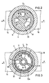
- the switching valve shown in Figs. 1 and 5 is an example of a 3/2-way valve 2, in particular for pneumatic pressure media, e.g. Compressed air.
- the valve 2 has a housing 4, preferably made of plastic, with an i.w. cylindrical, one-sided open housing chamber 6. In its area opposite the open side, the housing chamber 6 is delimited by a bottom 8 perpendicular to the longitudinal axis 7 of the valve, in the area of which three channels 10 and 12 (FIG. 1) and 14 (FIG. 5) open into the housing chamber 6.
- FIG. 1 the section in FIG.
- the channels 10, 12 and 14 each have a cross section at least in their mouth region in the form of a circular ring segment, all three circular ring segments lying on a common, imaginary circular ring concentric with the longitudinal axis 7.
- the channels 10, 12, 14 and their mouths are each offset by approximately 90 to one another, the channels 10 and 12 being diametrically opposite.
- the mouth of each channel 10, 12, 14 covers an angular range of approximately 30 ° in the circumferential direction.
- the channels 10 and 12 run through connecting pieces 16 and 18 of the housing 4 arranged obliquely to the longitudinal axis 7, wherein connecting pieces 16, 18, not shown, can be connected to pressure medium lines which lead to a pressure medium source P or to a consumer A.
- the third channel 14 can simply be open to the outside, while the channel 14 would be connected via a line to a pressure medium tank in the case of a valve provided for hydraulic media.
- the valve 2 now serves, in a first switching position, the so-called venting position (FIGS. 1 and 5), to connect the consumer A or the channel 10 to the channel 14 leading to the outside or to a pressure medium tank and to the To close pressure medium source P leading channel 12.
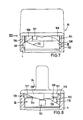
- the so-called ventilation position FIGGS. 7 and 8
- the consumer A or the duct 10 is to be connected to the pressure medium source P or to the duct 12 and the ventilation duct 14 is to be closed.
- two disk-shaped valve elements 20, 22 are arranged in the housing chamber 6, which preferably consist of ceramic material, or else of a suitable plastic or a ceramic-plastic combination.
- the two valve elements 20 and 22 are in direct face-to-face contact, which results in a sealing surface 24 due to their extremely smooth surfaces and the resulting adhesive effect between the valve elements 20, 22, without additional seals being necessary.
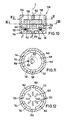
- the valve element 20 closest to the bottom 8 of the housing chamber 6 serves as a distributor disk and is mounted in the housing 4 so that it cannot rotate, for which purpose preferably two peg-like projections 26 on the bottom 8 (see FIG. 4). are arranged, which positively engage in corresponding receiving recesses (not visible in the drawing) on the side of the valve element 20 facing the bottom 8. How from
- the valve element 20 has a through opening 28 aligned with the consumer channel 10 and a through opening 30 aligned with the venting channel 14.
- These through openings 28 and 30 each have a channel 10, 14 i.w. congruent shape, i.e. they are also designed in the form of a segment of a circular ring, and they likewise cover an angular range of approximately 30 in each case in the circumferential direction.
- the valve element 20 has, on its side facing the bottom 8 of the housing chamber 6, an indentation 32 in the form of an annular segment with two walls parallel to the longitudinal axis 7 and a bottom perpendicular to this (FIG.
- the indentation 32 starting out extends from its end region covering the pressure channel 12 in the circumferential direction away from the ventilation channel 14 and towards the consumer channel 10 (see FIG. 2), namely the depression 32 covers an angular range of approximately 90 °.
- the valve element 20 has a through opening 34 in the end region of the recess 32 facing the circumferential direction of the through opening 28 covering the consumer channel 10, the shape of which corresponds to the through openings 28 and 30 due to this described configuration is the mouth of the pressure channel 12 practically via the valve element 20, ie Via the recess 32 and the through opening 34, offset in the circumferential direction towards the consumer duct 10 and away from the ventilation duct 10, specifically by an angle of approximately 600, which can be seen in particular in FIG. 6, since here the mouth of the channel 12 is shown in dashed lines.
- the through opening 34 of the valve element 20 thus represents the actual opening of the channel 12 on the side of the valve element 20 facing the other valve 22, which is to be indicated by the reference number 12a.
- a profile seal 36 is arranged between the bottom 8 of the housing chamber 6 and the valve element 20, which according to FIG. 4 encloses the mouths of the channels 10, 12 and 14 in each case .
- the profile seal 36 consists of an outer ring 36a, which encloses all channels 10, 12, 14 together. Starting from the ring 36a, sealing sections 36b extend approximately radially inwards on both sides next to the consumer channel 10 and the ventilation channel 14 and are connected to one another via a connecting section 36c.
- the profile seal 36 has an opening 36d into which a positioning lug 38 arranged on the bottom 8 of the housing chamber 6 engages, as a result of which the profile seal 36 is held in the housing 4 in a rotationally fixed manner.
- An elevation 40 of the base 8 is used to position the flexible area of the ring 36a, which is approximately diametrically opposite the channels 36a and, in the example shown, extends on a circular arc between the projections 26, which hold the valve element 20 against rotation.
- the channels 10 and 14 can be surrounded by webs 39 which extend axially from the base 8 and which in turn are enclosed by the profile seal 36.
- the second valve element 22 serves as a control disk and, for this purpose, is rotatably mounted in the housing 4 relative to the first, fixed valve element 20.
- the second valve element 22 has a smaller diameter than the first valve element 20, so that the latter projects radially outward with an annular projection surface 41 over the second valve element 22 (see FIGS. 1 and 5).
- the second valve element 22 has, according to the invention, a passage opening 42 in the form of an annular segment, which extends in the circumferential direction over an angular range of approximately 160.
- the valve element 22 has an annular segment-shaped depression 44 with walls parallel to the longitudinal axis 7 and a bottom perpendicular to this.
- the recess 44 extends in the circumferential direction over an angular range of approximately 1200.
- the through opening 42 is, seen in the circumferential direction, spaced from the recess 44 on one side by approximately 20 and on the other side by approximately 60 ° .
- the through opening 42 and the recess 44 are also like the mouths of the channels 10, 12, 14 and the through openings 28, 30, 34 of the first valve element 20 on the same imaginary, common circular ring 7 concentric with the longitudinal axis 7, so that they form the channels , or the through openings 28, 30 and 34 of the valve element 20 can each cover.
- valve element 22 has a central through-opening 46 which is circular in cross section and which is closed on one side by the first valve element 20 and which decreases in diameter in a direction facing away from the first valve element 20 via an annular step 48 (FIGS. 1 and 5).
- the second valve element 22 In the first switching position shown in FIG. 6, that is to say in the so-called venting position, the second valve element 22 is in a rotational position in which it passes through with the recess 44 passage openings 28 and 30 of the first valve element 20 covered and thereby connects the consumer channel 10 with the ventilation channel 14, ie the consumer A vented.
- the passage opening 42 of the second valve element 22 covers an area of the first valve element 20 in which only the actual opening 12a of the pressure channel 12, ie the passage opening 34 of the first valve element 20, is arranged, so that consequently the pressure channel 12 passes through the valve 2 is closed.
- the second valve element 22 is in a rotational position rotated by 90 in relation to FIG. 6, in which the actual opening 12a of the pressure channel 12, ie covers the passage opening 34 of the first valve element 20 and the consumer channel 10 or the passage opening 28 of the first valve element 20 and thereby connects the consumer A to the pressure P (vented).
- the recess 44 only covers the through opening 30 of the first valve element 20 or the ventilation channel 14, which is closed thereby.
- the configuration according to the invention in particular in that the passage opening 42 of the second valve element 22 always covers the actual mouth 12a of the pressure channel 12, ensures that the pressure P in all valve positions passes through the passage opening 42 to the top of the second valve element 22 facing away from the first valve element 20, whereby this is advantageously pressed against the first valve element 20, since an effect of the pressure on the side of the valve element 22 facing the valve element 20 due to the sealing effect between the valve elements 20, 22 ( Sealing surface 24) is excluded. In this way, a "zero gap" between the valve elements 20 and 22 is always guaranteed, even at high system pressures, so that contamination of the sealing surface 24 is almost completely excluded.
- the contact pressure of the second valve element against the first valve element 20 regulates itself automatically with the system pressure, i.e. the higher the system pressure, the higher the contact pressure and thus also the security against a pressure-related pushing apart of the valve elements 20, 22.
- a driver element 50 is arranged in the housing for rotating the second valve element 22 with respect to the fixed valve element 20.
- this driver element 50 consists of a circular disk part 52 arranged parallel to the second valve element 22 on its side facing away from the first valve element 20, and on its surface facing the second valve element 22 at least one in both Has circumferential directions positively engaging in the through-opening 42 of the second valve element 22, annular segment-shaped driver projection 54.
- annular segment-shaped driver lugs 54 are provided, each of which abuts the second valve element 22 for rotary driving in the end regions of the passage opening 42, and between which a gap remains in the circumferential direction, via which the pressure P through the passage opening 42 passes in the manner described above Top of the valve element 22 is applied.
- the disc part 52 also has a central, an axial slot 55 (see FIG. 5) having locking lug 56 which extends into the central through opening 46 of the valve element 22 and engages behind the ring step 48 in the through opening 46 with a locking edge 58, whereby the locking projection 56 is divided into two radially spring-elastic locking arms due to the axial slot 55.
- the locking projection 56 enables the second valve element 22 to be easily assembled by preassembling it on the driver element 50 via the locking projection 56 and inserting it together with the latter into the housing chamber 6.
- the locking projection 56 is concentrically surrounded by an annular groove 60 which extends axially into the disk part 52 and in which a compression spring 62 in the form of a spiral spring is arranged under prestress, which is supported on one side in the base of the annular groove 60 and on the other side on the second valve element 22.
- the housing chamber 6 is closed in a pressure-tight manner by a closure part 70.
- This closure part 70 consists of two hollow cylinder sections 72 and 74 with different diameters, which in the radial direction into one another via a disk ring 76 change over.
- the bottom hollow cylinder section 72 facing the bottom 8 of the housing chamber 6 has a larger diameter than the other, upper hollow cylinder section 74, concentrically surrounds the two disk parts 52 and 64 of the driving element 50 and the second valve element 22 and is already seated with an end-face annular surface on the top mentioned projection surface 41 of the first valve element 20.
- the upper hollow cylinder section 74 concentrically surrounds the sealing shoulder 66 of the driver element 50, the sealing ring 68 sealingly abutting the inner peripheral surface of the upper hollow cylinder section 74.
- the closure part 70 has a radially outward-pointing, circumferential ring web 78, which is seated on an annular step of the housing chamber 6 in the axial direction and is integrally connected to the housing 4, in particular ultrasonically welded.
- the housing chamber 6 is closed in a pressure-tight manner by the closure element 70, specifically because of the extensive welding to the housing 4 in the region of the annular web 78 and because of the gap between the driver element 50 or the sealing projection 66 and the upper hollow cylinder section. 74 sealing ring 68.
- the lower hollow cylinder section. 72 of the closure part 70 presses the first valve element 20 axially over the protruding surface 41 in the direction of the bottom 8 of the housing chamber 6 or against the profile seal 36 after the connection to the housing 4 in the region of the annular web 78, which thereby results in mutual sealing of the channels 10, 12 and 14 is biased.
- the rotatable entraining element 50 Due to the non-detachable connection between the closure part 70 and the housing 4, the rotatable entraining element 50 also sits firmly in the housing 4 in the axial direction, since the disc part 64 comes into contact with the inner annular surface of the disc ring 76 of the closure part 70.
- driver section 80 which has a preferably square cross-section which deviates from the circular shape and engages positively in a driver receptacle 82 of a rotary knob 84 which adjoins the housing 4 axially.
- the driver element 50 which is held in the housing 4 due to the closure part 70, has a pin-shaped latching projection 86 in the axial connection to the driver section 80, which extends into an axial opening 87 of the rotary knob 84 and has a ring step 90 with a latching edge 88 engages behind the opening 87.
- the locking projection 86 has an axial slot 92, as a result of which it is divided into two radially spring-elastic locking tangs which are chamfered at the ends. It is furthermore advantageous if a locking pin 94 is axially inserted into the outwardly open opening 87 of the rotary knob 84 from above, which engages with a pin section 96 between the locking arms of the locking projection 86 and thus holds them in their radially spread locking position, as a result of which the rotary knob 84 is secured against unwanted loosening. A loosening of the rotary knob 84 is nevertheless possible by removing the locking pin 94 beforehand.
- valve 2 has a resetting mechanism for automatically resetting the second valve element 22 from the second switching position (venting position Fig. 3,7,8) back to the first switching position (venting position, Fig. 1,5,6).
- This reset mechanism will be explained in the following in particular with reference to FIGS. 1,5,7,8 and 9.
- a reset ring 100 (corresponds to the individual part IX) is arranged in the housing 4, which on the one hand is displaceable in the axial direction and on the other hand rotatably in the circumferential direction in the housing 4.
- the reset ring 100 has two for example diametrically opposed, radial lugs 102, which each engage in an axial groove 104 in the interior of the housing 4 and are guided displaceably in the direction of the longitudinal axis 7 of the valve.
- a prestressed compression spring 106 (see FIGS.
- the rotary knob 84 preferably has two diametrically opposed cams 108 which extend axially in the direction of the reset ring 100 and which rest on an axially opposite, circumferential cam surface 110 of the reset ring 100.
- FIG. 9 A development of the return ring 100 or the cam surface 110 is shown in FIG. 9. From this it can be seen that the cam surface 110 has two identical sections, each of which, starting from a locking recess 112 arranged at 0 ° or 180, extends over an angular range of approximately 30 perpendicular to the longitudinal axis 7 of the valve, relative to the locking recess 112 in the direction of Rotary knob 84 has a slightly offset region 114 as well as an inclined surface 116 which adjoins this region 114 and extends over an angular range of approximately 60 in a direction inclined away from the rotary knob 84, the inclined surface 116 extending further away from the rotary knob 84 in the axial direction stretches as the locking recess 112 and ends at a stop edge 118 which extends essentially parallel to the longitudinal axis 7.
- the stop edge 118 is adjoined by a region 120 which extends over an angular range of approximately 70 perpendicular to the longitudinal axis 7 and which at 160 or 340 again merges into the latching recess 112.
- the area 120 is somewhat closer to the rotary knob 84 than the area 114.
- the reset mechanism now works as follows.
- the cams 108 of the rotary knob 84 are in abutment against the stop edges 118 at the lowest point of the inclined surfaces 116.
- the ventilation position By rotating the rotary knob 84 in the direction of the second switching position, the ventilation position, the cams 108 move in the direction of the arrow 122 over the cam surface 110, as a result of which, due to the inclined surfaces 116, the return ring 100 is displaced axially in the direction of the arrows 124 against the force of the spring 106, as a result of which its pretension increases.
- the cams 108 When the rotary knob 84 is turned further, the cams 108 initially move in the direction of the arrow 122 over the cam surface regions 114 until they engage in the latching depressions 112 in the second switching position.
- the return ring 100 moves back again somewhat in the axial direction against the direction of the arrow 124.
- the ventilation position is thus defined by the engagement of the cams 108 in the locking recesses 112.
- the rotary knob 84 only needs to be turned by an angle of approximately 30 until the cams 108 in the direction of the arrow 126 reach the areas of the inclined surfaces 116 from the recesses 112 via the cam surface regions 114.
- the return ring 100 is automatically axially in the direction of the rotary knob 84, i.e. moved back in the direction of the arrow 124a and, due to the inclined surfaces 116, the cams 108 moved further in the direction of the arrow 126, i.e. the knob 84 continues to be turned until the starting position is reached again, in which the cams 108 rest against the stop edges 118.
- the venting position is hereby achieved in any case if the rotary knob is turned at least 30.
- the remaining rotation of about 60 required to reach the venting position is advantageously carried out automatically due to the reset mechanism according to the invention, so that the valve of the present invention also meets the highest safety requirements
- the rotary knob 84 additionally has at least one, but preferably two diametrically opposite stop cams 127, each of which extends in the axial direction into a circumferential housing recess 128.
- Each housing recess 128 extends in the circumferential direction over less than 1800, so that it is delimited by two stop edges 129.
- the design and arrangement of the stop cams 127 and the stop edges 129 is according to the invention such that the stop cams 127 abut one of the two stop edges 129 in each of the two switching positions of the valve according to the invention, which advantageously reinforces the latching action between the cams 108 and the cam surface 110 will, ie the two switching positions of the switching valve are defined even more clearly.
- the invention can also be implemented with any other valves, for example with 2/2-way valves. It is only essential that the system pressure acts on the surface of the second valve element (control disk) facing away from the first valve element (distributor disk), so that the second valve element is pressed against the first valve element seated firmly in the housing.
- a valve 130 which in turn has two disk-shaped valve elements in a valve housing 132 or in its housing chamber 134, namely a first valve element 136 and a second valve element 138.
- the housing chamber 134 is preferably cylindrical with a bottom 140 perpendicular to the longitudinal axis 7 of the valve.
- the first valve element 136 is rotatably independent of the second valve element 138 and is held in the housing 132 in the axial direction
- the second valve element 138 is rotatably supported relative to the first valve element 136 by means of an only indicated driver element 142.
- the housing chamber 134 is closed in a manner analogous to FIGS. 1 to 9 by a closure part, not shown in FIG. 10.
- a channel 144 connected to a pressure medium source P opens into the housing chamber 134 in the radially outer region of the bottom 140.
- the first valve element 136 has at least one axial slot opening 146 on its outer circumference in the region of the mouths of this pressure channel 144, as a result of which a pressure medium Via the channel 144 and the slot opening 146, axially past the two valve elements 136, 138 into the area above the second valve element 138, which in turn has a smaller diameter than the first valve element 136, and here again the surface facing away from the first valve element 136 surface of the second valve element.
- the second valve element 138 is thereby pressed against the first valve element 136 by the system pressure, which always ensures the desired “zero gap” between the valve elements 136 and 138.
- the first valve element 136 preferably consists of a circular disk part 148 with radial projections 150, between which the slot openings 146 are formed in each case.
- the first valve element 136 has in the circular disk part 148 a plurality of through openings 152 lying on a circle concentric with the longitudinal axis 7 and preferably arranged uniformly distributed over the circumference a common channel 156 leading to a consumer A opens.
- the second valve element 138 has only one through opening 158, which is arranged such that when the second valve element 138 rotates, it can be made to coincide with each of the through openings 152 of the first valve element 136, at least in regions.
- the through openings 152 and 158 can be formed with different cross-sectional shapes.
- the through openings 152 of the first valve element 136 according to FIG. 11 are circular and according to FIG. 12 in the form of radially arranged elongated holes.
- the passage opening 158 of the second valve element 138 is also designed, for example, as an elongated hole.
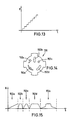
- valve 130 is particularly suitable for use in a so-called cascade connection, the second valve element 138 being driven by means of a motor drive, in particular by means of a stepping motor.
- the existing in a consumer A output pressure P receives a those shown in Fig. 13, zeitilchen course, that the pressure P rises a stepped manner on.
- the course of the stair-shaped rise can additionally be controlled by appropriate shapes of the through openings 152 and / or 158.
- Various alternatives for through openings 152 are indicated in FIG. 14.
- the through opening 152a has a triangular cross section
- the through opening 152b has a radially arranged elongated hole cross section
- the through opening 152c has a circular cross section
- the through opening 152d has a longitudinally curved cross section
- the through opening 152e has a circular cross section with two circumferentially extending, tapering sections.
- the diagram according to FIG. 15 shows the respective flow of the flow rate Q of a pressure medium over the rotation path s of the valve element 138.
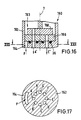
- the valve 160 illustrated in FIGS. 16 and 17 has in its housing 162 a pressure channel 164 opening into the housing chamber 163 analogous to the embodiment according to FIG. 10, but with a large number of output channels, for example eight output channels A ', B', C ', D', E ', F', G 'and H' (see the section in Fig. 17).
- the first valve element 166 is formed in the area of its outer circumference analogously to the embodiment according to FIG. 10 and has through openings which are aligned with the mouths of the outlet channels A 'to H'.
- the design of the second valve element 168 corresponds to that according to FIG. 10.
- the output channels A 'to H' can be selectively connected to the pressure channel 164, so that one of several consumers can optionally be activated.
- the second valve element 168 is pressed against the first valve element 166 by the system pressure.
Landscapes
- Engineering & Computer Science (AREA)
- General Engineering & Computer Science (AREA)
- Mechanical Engineering (AREA)
- Transportation (AREA)
- Multiple-Way Valves (AREA)
Claims (23)
caractérisée en ce que le deuxième élément de soupape (22), qui est mobile, présente au moins une ouverture de passage (42) en forme de segment de cercle telle qu'elle couvre au moins partiellement, dans chaque position de commande, l'ouverture de passage (34) reliée au canal d'entrée (12) du premier élément de soupape (20), ainsi que, dans au moins l'une des positions de commande, également l'une des autres ouvertures de passage (28), de manière à ce que, pour engendrer la pression, le deuxième élément de soupape (22) subisse sur sa face située à l'opposé du premier élément de soupape (20), dans chaque position de commande, la pression de système de l'agent de pression régnant dans le canal d'entrée (12).
caractérisée en ce que la surface du deuxième élément de soupape (22) qui est située à l'opposé du premier élément de soupape (20) et soumise à la pression est suivie d'une région de la chambre (6) de boîtier qui est reliée par les ouvertures de passage (34, 42) des éléments de soupape (20, 22) au canal (12) d'entrée de la pression.
caractérisée en ce que la chambre (6) est cylindrique et présente un fond (8) disposé perpendiculairement à l'axe longitudinal (7) du boîtier, les canaux (10, 12, 14) débouchant dans la chambre (6) dans la région du fond (8) et étant ensuite prolongés respectivement par les ouvertures de passage (28, 30, 34) du premier élément de soupape stationnaire (20) situé en regard du fond (8), un joint profilé (36), qui sépare hermétiquement les canaux entre eux, étant disposé entre le premier élément de soupape (20) et le fond (8) du boîtier.
caractérisée par un mécanisme de rappel qui retourne le deuxième élément de soupape (22) à partir d'une deuxième position de commande, après une légère rotation manuelle, automatiquement dans une première position de commande.
caractérisée par un mécanisme de rappel qui retourne le deuxième élément de soupape (22) à partir d'une deuxième position de commande, après une légère rotation manuelle, automatiquement dans une première position de commande.
caractérisé en ce que, dans le boîtier (4, 132, 162), sont disposés deux éléments de soupape (20, 22 ; 136, 138 ; 166, 168), le premier élément de soupape (20, 136, 166) étant monté stationnaire dans la direction axiale et circonférentielle dans la chambre (6, 134, 163), indépendamment du deuxième élément de soupape (22, 138, 168) et le deuxième élément de soupape (22, 138, 168) étant monté rotatif.
caractérisée en ce que la surface du deuxième élément de soupape (22, 138, 168), opposée au premier élément de soupape (20, 136, 166), est suivie d'une région de la chambre de boîtier (6, 134, 163) qui est reliée au canal d'entrée de la pression (12, 144, 164).
caractérisée en ce que la chambre de boîtier (4, 134, 163) est cylindrique avec un fond (8, 140) disposé perpendiculairement à l'axe longitudinal (7) du boîtier, les canaux (10, 12, 14 ; 144, 156, 164 ; A' à H') débouchant dans la chambre de boîtier (6, 134, 163) dans la région du fond (8, 140), et le premier élément de soupape (20, 136, 166), stationnaire et en regard du fond (8, 140), présentant des ouvertures de passage (28, 30, 34 ; 146, 152) reliées aux canaux, et un joint profilé (36) qui sépare hermétiquement les canaux entre eux étant disposé entre le premier élément de soupape (20, 136, 166) et le fond (8, 140) du boîtier.
caractérisée en ce que le deuxième élément de soupape (22) qui est monté rotatif possède au moins une ouverture de passage axiale (42) qui coïncide au moins partiellement dans chaque position de rotation avec l'ouverture de passage (34) du premier élément de soupape (20) reliée au canal de pression (12).
caractérisée en ce que le diamètre du premier élément de soupape (20, 136, 166) est supérieur à celui du deuxième élément de soupape (22, 138, 168) de manière à projeter par rapport à celui-ci dans la direction radiale d'une surface (41), un organe de fermeture (70) qui a la forme d'un cylindre creux et qui entoure le deuxième élément de soupape rotatif (22, 138, 168) étant posé sur la surface de projection (41) et poussant le premier élément de soupape (20, 136, 166) contre le joint profilé (36).
caractérisée en ce que la périphérie extérieure de l'organe de fermeture (70) est reliée par engagement de matières, et en particulier par soudure à ultrasons, au boîtier (4, 132, 162).
caractérisée en ce qu'un élément d'entraînement axial (50) s'étend à travers l'organe de fermeture (70), cet élément étant solidaire en rotation avec le deuxième élément de soupape (22, 138, 168) et étanché par rapport à l'organe de fermeture (70) à l'aide d'un joint (68).
caractérisée en ce que le premier élément de soupape (136, 166) possède, dans la région de la surface de projection (41) au moins une fente axiale (146) qui recouvre au moins partiellement le canal d'entrée de la pression (144, 164).
caractérisée en ce que l'élément d'entraînement (50) présente une saillie d'arrêt (56) axiale qui s'engage mécaniquement et/ou par force dans une ouverture centrale (46) du deuxième élément de soupape (22, 138, 168).
caractérisée en ce que l'élément d'entraînement (50) présente au moins une saillie d'entraînement (54) s'engageant mécaniquement dans les deux directions circonférentielles dans l'ouverture de passage (42) du deuxième élément de soupape (22).
caractérisée en ce qu'un ressort de pression précontraint (62) est disposé entre l'élément d'entraînement (50) et le deuxième élément de soupape (22, 138, 168).
caractérisée en ce que l'élément d'entraînement (50) s'appuie sur l'organe de fermeture (70) dans une direction axiale opposée aux éléments de soupape.
caractérisée en ce qu'une portion d'entraînement (80) de section transversale de préférence carrée, de l'élément d'entraînement (50) s'engage mécaniquement dans un logement (82) d'un bouton rotatif (84).
caractérisée en ce qu'un prolongement cranté (86) de l'élément d'entraînement (50) s'engage par force et/ou mécaniquement dans une ouverture axiale (87) du bouton rotatif (84).
caractérisée en ce que le prolongement cranté (86) a la forme d'une broche et présente une fente axiale (92), une cheville de sécurité (94) étant disposée dans l'ouverture axiale (87) du bouton rotatif (84), une portion (96) de cette cheville s'engageant dans la fente (92) de la saillie d'arrêt (86).
caractérisé en ce que le mécanisme de rappel présente une bague de rappel (100) disposée dans le boîtier (4), entre le bouton rotatif (84) et l'organe de fermeture (70), cette bague étant disposée dans le boîtier (4) mobile dans la direction axiale et bloquée en rotation dans la direction circonférentielle, un ressort de pression précontraint (106) étant disposé entre la bague de rappel (100) et l'organe de fermeture (70), et le bouton rotatif (84) présentant des cames (108) qui s'étendent axialement dans la direction de la bague de rappel (100) et sont appliquées sur une surface périphérique (110) de la bague de rappel (100) axialement en regard.
caractérisée en ce que le bouton rotatif (84) présente deux cames (108) diamétralement en regard et que la surface (110) de la bague de rappel (100) présente deux portions identiques, qui, partant d'un évidement d'arrêt (112) prévu à 0 ° , respectivement à 180° présentent une région (114) s'étendant sur une région angulaire d'environ 30 perpendiculairement à l'axe longitudinal (7) de la soupape, légèrement décalée dans la direction du bouton rotatif (84) par rapport à l'évidement d'arrêt (112), ainsi qu'une surface (116) qui y fait suite, inclinée sur une région angulaire de 60 environ dans une direction opposée au bouton rotatif (84), la surface inclinée (116) aboutissant à l'endroit d'un bord d'arrêt (118) sensiblement parallèle à l'axe longitudinal (7), suivi à son tour d'une région (120) s'étendant sur un angle de 70 environ perpendiculairement à l'axe longitudinal (7) et suivi, à 160°, respectivement à 340 ° , de nouveau par l'évidement d'arrêt (112).
caractérisée en ce que le bouton rotatif (84) présente au moins une, de préférence deux, cames d'arrêt (127) situées diamétralement en regard, chaque came d'arrêt (127) s'étendant dans la direction axiale dans un évidement périphérique (128) du boîtier, limité dans la direction périphérique par deux bords d'arrêt (129) contre lesquels est alternativement appliquée la came d'arrêt (127) dans la première ou la deuxième position de commande.
Applications Claiming Priority (2)
| Application Number | Priority Date | Filing Date | Title |
|---|---|---|---|
| DE3808899A DE3808899A1 (de) | 1988-03-17 | 1988-03-17 | Schaltventil |
| DE3808899 | 1988-03-17 |
Publications (3)
| Publication Number | Publication Date |
|---|---|
| EP0333088A1 EP0333088A1 (fr) | 1989-09-20 |
| EP0333088B1 EP0333088B1 (fr) | 1991-10-09 |
| EP0333088B2 true EP0333088B2 (fr) | 1994-10-12 |
Family
ID=6349948
Family Applications (1)
| Application Number | Title | Priority Date | Filing Date |
|---|---|---|---|
| EP89104378A Expired - Lifetime EP0333088B2 (fr) | 1988-03-17 | 1989-03-13 | Soupape de commande |
Country Status (2)
| Country | Link |
|---|---|
| EP (1) | EP0333088B2 (fr) |
| DE (2) | DE3808899A1 (fr) |
Families Citing this family (7)
| Publication number | Priority date | Publication date | Assignee | Title |
|---|---|---|---|---|
| DE19614653A1 (de) * | 1996-04-13 | 1997-10-16 | Grohe Armaturen Friedrich | Ventil |
| FR2759962B1 (fr) * | 1997-02-25 | 1999-05-14 | Renault Vehicules Ind | Vanne pneumatique notamment pour dispositif de freinage d'un vehicule automobile |
| CN100478593C (zh) * | 2004-09-20 | 2009-04-15 | 周宛良 | 水龙头的切换装置 |
| EP2418409B1 (fr) * | 2010-08-12 | 2012-10-03 | Grohe AG | Poignée tournante |
| JP6510810B2 (ja) * | 2014-12-26 | 2019-05-08 | 株式会社不二工機 | 流路切換弁 |
| JP6945859B2 (ja) * | 2018-06-04 | 2021-10-06 | 株式会社不二工機 | 流路切換弁 |
| CN116624622B (zh) * | 2023-05-30 | 2026-04-14 | 徐州徐工施维英机械有限公司 | 控制阀、液压系统和混凝土泵送设备 |
Family Cites Families (3)
| Publication number | Priority date | Publication date | Assignee | Title |
|---|---|---|---|---|
| US2653003A (en) * | 1946-10-26 | 1953-09-22 | John W Overbeke | Control valve |
| GB1240480A (en) * | 1967-08-17 | 1971-07-28 | Daikin Ind Ltd | Directional control valve |
| DE3539316A1 (de) * | 1985-11-06 | 1987-05-07 | Voss Armaturen | Schaltventil mit keramischen ventilelementen |
-
1988
- 1988-03-17 DE DE3808899A patent/DE3808899A1/de not_active Withdrawn
-
1989
- 1989-03-13 DE DE8989104378T patent/DE58900344D1/de not_active Expired - Lifetime
- 1989-03-13 EP EP89104378A patent/EP0333088B2/fr not_active Expired - Lifetime
Also Published As
| Publication number | Publication date |
|---|---|
| EP0333088B1 (fr) | 1991-10-09 |
| EP0333088A1 (fr) | 1989-09-20 |
| DE3808899A1 (de) | 1989-09-28 |
| DE58900344D1 (de) | 1991-11-14 |
Similar Documents
| Publication | Publication Date | Title |
|---|---|---|
| DE68903457T2 (de) | Rueckschlagventil. | |
| EP0321500B1 (fr) | Soupape de fermeture pour fluides | |
| EP1196706A1 (fr) | Vanne de melange sanitaire | |
| EP0333088B2 (fr) | Soupape de commande | |
| EP4302003B1 (fr) | Dispositif de soupape | |
| CH687561A5 (de) | Sanitaeres Einhebel-Mischventil. | |
| EP3447346B1 (fr) | Soupape, en particulier servosoupape | |
| DE4135858A1 (de) | Scheibenventil | |
| DE3815350A1 (de) | Kupplung fuer fluidleitungen | |
| DE69404892T2 (de) | Drosselklappe | |
| DE2900601C2 (de) | Absperrventil für ein Fluid | |
| EP0311598B1 (fr) | Cartouche de robinet pour vanne à une voie | |
| EP3940272A1 (fr) | Robinet d'arrêt, particulièrement pour une utilisation dans le domaine sanitaire | |
| EP0221231B1 (fr) | Soupape de commande avec des éléments de valve céramiques | |
| EP0271661B1 (fr) | Dispositif pour transmettre une force de commande entre deux pièces de construction | |
| EP1321698A2 (fr) | Dipositif pour connecter plusieurs composants hydrauliques ou pneumatiques, en particulier soupapes électromagnétiques | |
| DE3539316A1 (de) | Schaltventil mit keramischen ventilelementen | |
| DE69006355T2 (de) | Absperrventil. | |
| LU87400A1 (de) | Ventilanordnung zum fuellen und entleeren eines gasbehaelters | |
| DE3935389A1 (de) | Mischventil | |
| EP0335997A1 (fr) | Tête de robinet | |
| DE10142143A1 (de) | Antriebsvorrichtung für eine Beregnungsvorrichtung | |
| DE29814385U1 (de) | Mehrwegeventil | |
| DE4105070C2 (de) | Ventil | |
| DE3130291C2 (de) | Schrittschaltgetriebe |
Legal Events
| Date | Code | Title | Description |
|---|---|---|---|
| PUAI | Public reference made under article 153(3) epc to a published international application that has entered the european phase |
Free format text: ORIGINAL CODE: 0009012 |
|
| AK | Designated contracting states |
Kind code of ref document: A1 Designated state(s): DE FR GB IT NL SE |
|
| 17P | Request for examination filed |
Effective date: 19891107 |
|
| 17Q | First examination report despatched |
Effective date: 19910208 |
|
| GRAA | (expected) grant |
Free format text: ORIGINAL CODE: 0009210 |
|
| AK | Designated contracting states |
Kind code of ref document: B1 Designated state(s): DE FR GB IT NL SE |
|
| ITF | It: translation for a ep patent filed | ||
| GBT | Gb: translation of ep patent filed (gb section 77(6)(a)/1977) | ||
| REF | Corresponds to: |
Ref document number: 58900344 Country of ref document: DE Date of ref document: 19911114 |
|
| ET | Fr: translation filed | ||
| PLBI | Opposition filed |
Free format text: ORIGINAL CODE: 0009260 |
|
| 26 | Opposition filed |
Opponent name: KNORR-BREMSE AG Effective date: 19920423 |
|
| PLBI | Opposition filed |
Free format text: ORIGINAL CODE: 0009260 |
|
| NLR1 | Nl: opposition has been filed with the epo |
Opponent name: KNORR-BREMSE AG. |
|
| 26 | Opposition filed |
Opponent name: JOH. VAILLANT GMBH U. CO Effective date: 19920708 Opponent name: KNORR-BREMSE AG Effective date: 19920423 |
|
| NLR1 | Nl: opposition has been filed with the epo |
Opponent name: JOH. VAILLANT GMBH U. CO. |
|
| PUAH | Patent maintained in amended form |
Free format text: ORIGINAL CODE: 0009272 |
|
| STAA | Information on the status of an ep patent application or granted ep patent |
Free format text: STATUS: PATENT MAINTAINED AS AMENDED |
|
| 27A | Patent maintained in amended form |
Effective date: 19941012 |
|
| AK | Designated contracting states |
Kind code of ref document: B2 Designated state(s): DE FR GB IT NL SE |
|
| GBTA | Gb: translation of amended ep patent filed (gb section 77(6)(b)/1977) |
Effective date: 19940914 |
|
| ITF | It: translation for a ep patent filed | ||
| NLR2 | Nl: decision of opposition | ||
| ET3 | Fr: translation filed ** decision concerning opposition | ||
| NLR3 | Nl: receipt of modified translations in the netherlands language after an opposition procedure | ||
| EAL | Se: european patent in force in sweden |
Ref document number: 89104378.8 |
|
| PGFP | Annual fee paid to national office [announced via postgrant information from national office to epo] |
Ref country code: FR Payment date: 20000126 Year of fee payment: 12 |
|
| PGFP | Annual fee paid to national office [announced via postgrant information from national office to epo] |
Ref country code: GB Payment date: 20000308 Year of fee payment: 12 |
|
| PGFP | Annual fee paid to national office [announced via postgrant information from national office to epo] |
Ref country code: SE Payment date: 20000317 Year of fee payment: 12 |
|
| PGFP | Annual fee paid to national office [announced via postgrant information from national office to epo] |
Ref country code: NL Payment date: 20000329 Year of fee payment: 12 |
|
| PGFP | Annual fee paid to national office [announced via postgrant information from national office to epo] |
Ref country code: DE Payment date: 20000522 Year of fee payment: 12 |
|
| PG25 | Lapsed in a contracting state [announced via postgrant information from national office to epo] |
Ref country code: GB Free format text: LAPSE BECAUSE OF NON-PAYMENT OF DUE FEES Effective date: 20010313 |
|
| PG25 | Lapsed in a contracting state [announced via postgrant information from national office to epo] |
Ref country code: SE Free format text: LAPSE BECAUSE OF NON-PAYMENT OF DUE FEES Effective date: 20010314 |
|
| PG25 | Lapsed in a contracting state [announced via postgrant information from national office to epo] |
Ref country code: NL Free format text: LAPSE BECAUSE OF NON-PAYMENT OF DUE FEES Effective date: 20011001 |
|
| GBPC | Gb: european patent ceased through non-payment of renewal fee |
Effective date: 20010313 |
|
| EUG | Se: european patent has lapsed |
Ref document number: 89104378.8 |
|
| PG25 | Lapsed in a contracting state [announced via postgrant information from national office to epo] |
Ref country code: FR Free format text: LAPSE BECAUSE OF NON-PAYMENT OF DUE FEES Effective date: 20011130 |
|
| NLV4 | Nl: lapsed or anulled due to non-payment of the annual fee |
Effective date: 20011001 |
|
| REG | Reference to a national code |
Ref country code: FR Ref legal event code: ST |
|
| PG25 | Lapsed in a contracting state [announced via postgrant information from national office to epo] |
Ref country code: DE Free format text: LAPSE BECAUSE OF NON-PAYMENT OF DUE FEES Effective date: 20020101 |
|
| PG25 | Lapsed in a contracting state [announced via postgrant information from national office to epo] |
Ref country code: IT Free format text: LAPSE BECAUSE OF NON-PAYMENT OF DUE FEES Effective date: 20050313 |