EP0333123A2 - Système de communication RNIS à structure modulaire - Google Patents
Système de communication RNIS à structure modulaire Download PDFInfo
- Publication number
- EP0333123A2 EP0333123A2 EP89104481A EP89104481A EP0333123A2 EP 0333123 A2 EP0333123 A2 EP 0333123A2 EP 89104481 A EP89104481 A EP 89104481A EP 89104481 A EP89104481 A EP 89104481A EP 0333123 A2 EP0333123 A2 EP 0333123A2
- Authority
- EP
- European Patent Office
- Prior art keywords
- operating system
- real
- interrupt
- timeshare
- data
- Prior art date
- Legal status (The legal status is an assumption and is not a legal conclusion. Google has not performed a legal analysis and makes no representation as to the accuracy of the status listed.)
- Granted
Links
Images







Classifications
-
- G—PHYSICS
- G06—COMPUTING OR CALCULATING; COUNTING
- G06F—ELECTRIC DIGITAL DATA PROCESSING
- G06F9/00—Arrangements for program control, e.g. control units
- G06F9/06—Arrangements for program control, e.g. control units using stored programs, i.e. using an internal store of processing equipment to receive or retain programs
- G06F9/44—Arrangements for executing specific programs
- G06F9/455—Emulation; Interpretation; Software simulation, e.g. virtualisation or emulation of application or operating system execution engines
- G06F9/45533—Hypervisors; Virtual machine monitors
-
- G—PHYSICS
- G06—COMPUTING OR CALCULATING; COUNTING
- G06F—ELECTRIC DIGITAL DATA PROCESSING
- G06F9/00—Arrangements for program control, e.g. control units
- G06F9/06—Arrangements for program control, e.g. control units using stored programs, i.e. using an internal store of processing equipment to receive or retain programs
- G06F9/46—Multiprogramming arrangements
- G06F9/54—Interprogram communication
- G06F9/544—Buffers; Shared memory; Pipes
-
- H—ELECTRICITY
- H04—ELECTRIC COMMUNICATION TECHNIQUE
- H04Q—SELECTING
- H04Q11/00—Selecting arrangements for multiplex systems
- H04Q11/04—Selecting arrangements for multiplex systems for time-division multiplexing
- H04Q11/0428—Integrated services digital network, i.e. systems for transmission of different types of digitised signals, e.g. speech, data, telecentral, television signals
Definitions
- the invention relates to a modularly structured ISDN communication system according to the preamble of patent claim 1.
- Such modularly structured digital communication systems are used to connect end devices with diverse performance features to one another and to connect these end devices to communication networks, in particular public networks.
- Such a communication system is known from a special edition of "Telcom Report” - ISDN in the office - 1985 ISBN 3-8009-3846-4, Siemens Aktiengesellschaft, to which, among other things, digital telephones, facsimile machines, teletext and screen text stations can be connected.
- the modules of the communication system include what is known as an operating data server unit, which comprises a system-operating functional complex and various optional data application functions; the data application functions can be loaded and then activated.
- an operating data server unit which comprises a system-operating functional complex and various optional data application functions; the data application functions can be loaded and then activated.
- a special data server can be integrated into the system, which can only be used for data applications.
- the main data application functions in this context are:
- Such functions include the transport of various types of data between the actual communication system and local or remote data carriers and servers work systems.
- data to be transmitted include, among other things, charge data, traffic statistical data and different system and user files
- These functions are used to set up, edit and delete files on different data carriers for the purpose of data acquisition. This is done, for example, in connection with the connection data recording for the determination of charges as well as with the acquisition of traffic-statistical data for the monitoring of the system load.
- Such processing functions include, for example, the preparation of fee data according to different application-specific criteria for output on terminals and data carriers.
- All of these data application functions are implemented by software processes that are implemented in the operating data server unit or in a special data server.
- the individual units or servers are integrated in terms of operation and security. This is facilitated in particular by technological integration in the form of uniform processors, operating systems and memory in the servers.
- a modification of the known operating system iRMX 286 is provided as the operating system for this communication system, the essential criteria of which are 'multi-tasking' and 'multi-programming'; this operating system belongs to the genus of so-called real-time operating systems (real-time processing operating system).
- the object on which the invention is based is to insert a timeshare operating system into a communication system in such a way that data applications carried under the timeshare operating system can be inserted into the communication system without additional adaptation effort and that data and data applications managed by the real-time operating system allow access to the timeshare system. Operating system can be transferred.
- An essential advantage of the invention is that the timeshare operating system uses almost exclusively the computing power of the modular communication system which is the starting point of the invention and, in particular - apart from the memory requirement for program subsystems and files - does not require any expenditure or changes to hardware components.
- the UNIX Operating System for which extensive documentation is known, can be used as the timeshare operating system in the form of the application module.
- An essential structural feature of the invention is the data field provided in the intercommunication data segment for receiving, inter alia, interchangeable messages with the information transport system.
- the data structure of the data recorded in this data field can be chosen to be the same as the data structure of the interface between an operating system bus and modules of the communication system, in particular that between an operating and data server and the switching module.
- the data field of the intercommunication data segment therefore has an interface character and is used primarily for the exchange of messages and orders with the information transport system of the real-time operating system.
- the real-time operating system and the timeshare operating system each have their own table memory for storing descriptors.
- this transition is given a low priority compared to the priorities of the other program subsystems. This ensures that time-critical functions of the real-time operating system are processed with priority over all functions of the timeshare operating system.
- a preferred way of granting a certain priority is that the transition from the real-time operating system to the timeshare operating system takes place from an idle program subsystem (idle task).
- the transition from the timeshare operating system to the real-time operating system is preferably initiated by a periodic interrupt process, during which the data specified in the data field of the intercommunication data segment is read out into the respective input and output memory specific to the program subsystem.
- a periodic interrupt process during which the data specified in the data field of the intercommunication data segment is read out into the respective input and output memory specific to the program subsystem.
- FIG. 1 shows a communication computer together with a large number of connectable devices.
- Essential components of the communication computer are a switching unit SWU and an operating data server unit ADS. These two units are supplemented by a voice information server unit VMS and a text fax server unit TFS.
- the operating data server unit ADS is assigned an application module ASM, which is provided with a subscriber operating system.
- the units SWU, ADS, VMS, TFS and ASM are principally to be understood as pure software modules, i.e. that the selected display is not tied to a specific type and distribution of the hardware used.
- the switching unit SWU, the operational data server unit ADS and the application module ASM can be assigned the same processor device.
- this communication computer is functionally composed of only one switching unit SWU for the switching switching functions and one operational data server unit ADS for the storage switching functions.
- the two units are assigned their own hardware, each of which has the characteristics of a microcomputer system.
- Both system units are interconnected via a system bus in order to work together.
- the switching unit SWU is composed of three functional units, namely a peripheral driver unit with a plurality of connection units LTU to LTUn, a switching network and a control SWU.
- a microprocessor UPS, a memory unit MES and an interface processor IPS are indicated as individual components of the control SWU.
- the operational data server unit ADS essentially consists of an ADS control unit, a data memory MEM and line periphery LP.
- an operating terminal BT can also be connected to the operating data server unit.
- FIG. 3 shows the essential elements of the ADS control unit in a block diagram.
- these are the central processing unit UPA, a system memory MEA, a line bus controller LBC for the line peripherals LP, an output processor IOPS for the data memory MEM and an interface processor IPA for the system bus.
- Both system units have their own operating system as the basis for a programmatic implementation of the functions in the switching unit SWU and the operating data server unit ADS. However, both operating systems are linked to each other via the system bus. Since short response times are generally required, both operating systems must be designed as real-time operating systems.
- the operational data server unit ADS also provides the organization and control system unit entrusted with the entire communication system.
- the functions implemented for this purpose in the operational data server unit ADS can be subdivided into a system operational functional complex and into various optional data application functions.
- the system operating functions include e.g. commissioning the systems, loading system programs, distributing and starting these system programs, activating or deactivating system functions, and recording all operational changes.
- the data application functions essentially include data transport functions for transporting various types of data, such as charge data, system user files between the communication system and other data processing systems, as well as data acquisition functions, e.g. for charging or for traffic statistics and data processing functions, e.g. for the processing of determined data.
- data transport functions for transporting various types of data, such as charge data, system user files between the communication system and other data processing systems, as well as data acquisition functions, e.g. for charging or for traffic statistics and data processing functions, e.g. for the processing of determined data.
- the operating system installed in the company data server unit ADS is designed for partner operation and real-time processing, such as the well-known operating system iRMX286.
- the software architecture in the ADS control unit is illustrated in FIG. 4 using a shell model.
- the operating system OS Under the management of the operating system OS there is an operational and security-related software complex AM / DEP, a user system AS which performs the actual memory transfer function, a communication control system CMS for the execution of standardized communication protocols and a file management system DMS.
- a common database DB is accessible to all of these systems.
- a subscriber operating system also called a timeshare operating system, can be used to process independent tasks from individual terminals.
- Each user has their own input / output device as a link to the computer system. From this device he enters his programs as well as his data and control instructions.
- the functions of such a data processing system are software-integrated in the existing communication system. If the hardware is unchanged, the communication system then fulfills those of a data processing system in subscriber mode in addition to the switching tasks.
- the associated, additionally required computing power can only be provided by the operational data server unit ADS, since the switching unit SWU forms an independent and self-contained functional complex.
- the subscriber operating system managing the central processing unit of the operating data server unit ADS is modified such that it still guarantees the switching functions in connection with the switching unit SWU and on the other hand permits the desired subscriber operation. Since both modes of operation are in principle independent of each other and in the interest of the user a highly comfortable and well-known operating system is advantageous for the subscriber operation, the functions of the existing (subscriber operating system) real-time operating system e.g. iRMX are replaced by those of an independent subscriber operating system (timeshare operating system, e.g. UNIX or a variant of UNIX) added.
- timeshare operating system e.g. UNIX or a variant of UNIX
- both operating systems are conceptually designed for the sole management of a central processing unit, it is equipped with a special microprocessor, e.g. INTEL 80286 or 80386, possible as central processing unit PA, to couple the operating systems programmatically without significant changes, so that the operating power of the central processing unit uPA is accessible to both operating systems.
- a special microprocessor e.g. INTEL 80286 or 80386, possible as central processing unit PA, to couple the operating systems programmatically without significant changes, so that the operating power of the central processing unit uPA is accessible to both operating systems.
- the central processing unit uPA is successively assigned to one or the other operating system in chronological order. As is known, it also takes place within so-called multitasking operating systems, e.g. iRMX, also an assignment of the central processing unit to program sub-units, which are also referred to as program subsystems or frequently tasks or processes.
- multitasking operating systems e.g. iRMX
- program sub-units which are also referred to as program subsystems or frequently tasks or processes.
- Such tasks represent software units consisting of program code and data, which are entrusted with a specific function and enable a structured structure of an operating system.
- Each task in an operating system is usually assigned a so-called priority value, which expresses the importance of a particular task and is decisive for the allocation of the central processing unit in competition with other tasks.
- the part of the operating system that coordinates the assignment of the tasks and that corresponds to a sequence of tasks Task scheduler is defined according to its priority values.
- the task in question can keep the central processing unit until either a higher priority task applies for assignment of the central processing unit or until it issues the central processing unit itself. The latter is particularly true when a task needs certain information to be provided by other tasks to process its tasks and has to wait for this information to arrive.
- Each task of an operating system is thus at any one time in exactly one of essentially three operating states, which are referred to as “running", “ready” and “sleeping". Accordingly, the task that is currently assigned to the central processing unit is ongoing. All tasks that apply for allocation to the central processing unit are ready and the tasks that are waiting for the arrival of certain events are asleep.
- ideltask In the multi-tasking operating system, an additional so-called ideltask is usually provided, which has no specific function, but which is never asleep and, since it has the lowest priority value, is only running when all other tasks are asleep.
- the idletask present in the real-time operating system of the communication system is modified in such a way that, in the "running" state, it transfers the central processing unit uPA to the subscriber operating system without authorization, ie without operating system control.
- the idletask thus forms a kind of lock, with the help of which the central computing unit uPA can be removed from the real-time operating system and, of course, returned.
- the central processing unit must therefore be transferred in a command level and data level that are invisible to the two operating systems and interact directly with the central processing unit.
- a microprocessor of type 80286/80386 as a central processing unit uPA, the measures required to implement such a transfer are reduced considerably, since the hardware architecture of this microprocessor is already specialized for its use in multitasking operating systems.
- a multi-stage and table-oriented addressing process is implemented in this microprocessor to form physical addresses.
- the basic principle of this method is to address functionally contiguous memory blocks, hereinafter referred to as segments, in the address area of the main memory via descriptors and a clear assignment of these segments to individual program packages, e.g. Tasks to support hardware.
- a table is created in the main memory of the microprocessor, which is referred to as the global descriptor table GDT.
- This table GDT has a large number of so-called descriptors.
- the descriptors essentially represent an absolute address and length value with which the start address and the length of a memory block in the address area of the microprocessor are clearly defined.
- each of the descriptors has a unique place number.
- descriptors are named differently. For example, data segment descriptors are provided which define memory blocks in which only data is present or code segment descriptors for memory blocks in which only program code is stored.
- system segment descriptors that define the start address and length of memory blocks, which in turn are structured as a table, similar to the GDT.
- a local descriptor table descriptor LDTD defines a block of memory called a local descriptor table LDTD.
- a local descriptor table LDT in turn contains descriptors whose structure corresponds to that of the GDT, but no system segment descriptors are possible in an LDT.
- a (task) status segment descriptor TSSD defines a so-called (task) status segment TSS, which is also constructed as a table, but is mainly reserved for storing internal register contents in the microprocessor.
- each (task) status segment TSS there is also a pointer, also called an LDT selector, via which one of the LDTs specified by the GDT is assigned to the relevant TSS.
- the LDT selector represents the location number that the local descriptor table descriptor in the GDT has that defines the assigned LDT.
- the microprocessor itself provides a large number of hardware registers which, when a relative address is specified, enable the relative address to be dynamically assigned to a segment, so that an absolute address can be formed, via which a memory cell in the address area of the microprocessor is then selected.
- segment registers For each instruction that the microprocessor finds for execution, one of several so-called segment registers is clearly selected according to a given regulation.
- the segment registers contain either a location number of a GDT or a location number of an LDT.
- an associated descriptor is immediately selected in the GDT with a location number in the GDT. Since no location number is assigned for system segment descriptors, the descriptor selected via the location number specifies as the segment descriptor the start address and length of the segment in which a relative address possibly associated with the underlying command is to be addressed.
- a location number of an LDT is specified in a selected segment register, it must first be determined in which of the LDT's the location number should select a segment descriptor.
- the 80286/80386 microprocessor is well suited as a central processing unit in connection with multi-tasking operating systems.
- a distribution of the common tasks of the operating system to different software packages, so-called tasks, of which only one is running at any time, can be supported by the microprocessor in such a way that each task is assigned its own (task) status segment TSS, in which task-specific information and a reference to data and code segments belonging to the task in question are stored.
- a so-called task register TS is provided, in which the location number in the GDT that has the (task) status segment descriptor TSSD that is currently running Task heard.
- a current LDT is selected using the LDT selector stored in the relevant (task) status segment.
- the LDT selector represents the location number in the GDT that belongs to the local descriptor table descriptor LDTD that defines the current LDT.
- the current LTD is determined by the microprocessor when a current (task) status segment is selected via an internal local descriptor table register LDTR, in which the LDT selector taken from the current (task) status segment is entered.
- the current LDT is always meant, in which the location number in question then designates a segment descriptor in analogy to the GDT.
- a hardware task switchover also called a task switch or process change, is provided in the microprocessor.
- the data belonging to the previously running task are stored in the (task) status segment belonging to the task by internal processor control and replaced by the data belonging to the now running task.
- the task register TR and the local descriptor table register LDTR are set to the current (task) status segment or to the current LDT.
- interrupt descriptor table IDT For immediate processing of software and hardware events, a so-called interrupt descriptor table IDT, is made available to the microprocessor.
- the IDT contains references to all interrupt routines (also called interrupt handlers) that come into question when an event occurs (also called interrupt, incentive or interrupt request) in the form of a location number in the GDT or an LDT and a relative address.
- interrupt routines also called interrupt handlers
- an event also called interrupt, incentive or interrupt request
- a code segment descriptor Under the relevant location number in the GDT or an LDT is a code segment descriptor, which represents the address for a code segment containing a respective interrupt routine.
- the associated relative address is the start address of the interrupt routine within this code segment.
- an identification number that identifies the relevant event is used as the location number in the IDT in order to select the interrupt routine associated with the event via the GDT or an LDT.
- the absolute start address and the length of the IDT are set in an internal microprocessor register in the so-called interrupt descriptor table register IDTR.
- the idletask of the real-time operating system in the operating data server unit ADS of the communication system is designed as a lock subsystem so that the central processing unit uPA can be made available to the subscriber and the real-time operating system.
- both operating systems that is to say the operating system programs together with the associated data, are in the system memory MEA of the central processing unit uPA are stored. Since both operating systems have program structures that are independent of one another and are in principle independent, each of the operating systems has its own addressing tables in the form of exactly one GDT and IDT, as well as possibly several (task) status segments and local descriptor tables LDT.
- the GDT assigned to the real-time operating system is also referred to as a system table memory and the IDT as a further system table memory; the GDT assigned to the subscriber operating system is called module table memory and the IDT is called further module table memory.
- a common data descriptor is a data segment, a status segment and at least one code segment descriptor.
- the two common data segment descriptors define exactly one data segment, which is called the inter-communication data segment in the following, because it can be reached by both operating systems and can be used for data transfer.
- the two common code segment descriptors define a code segment in which program sequences are stored, which are processed during a transition from one operating system to another.
- This code segment is essentially used by the idletask of the real-time operating system, since the transition to the subscriber operating system takes place while the idletask is running.
- the two common status segment descriptors determine the (task) status segment belonging to the real-time operating system.
- the location number of the common status segment descriptors is stored together with the starting addresses and lengths of both GDT's and IDT's in the real-time operating system in the intercommunication data segment.
- the location number in which the status segment descriptor of the subscriber operating system is located is entered in the module table memory in the intercommunication data segment.
- central processing unit uPA Since the central processing unit uPA must be available to the real-time operating system for starting up the entire communication system, it is assumed that all the microprocessor-internal registers are set in accordance with the requirements of the real-time operating system before a first transition to the subscriber operating system.
- the code segment belonging to the idle task of the real-time operating system and defined by common code descriptors contains special instructions to the central processing unit uPA, which are executed while the idle task is running and prepare the transition to the subscriber operating system.
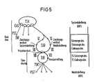
- FIG. 5 shows a schematic diagram of the program-related steps relevant to a transition from one operating system to another, in connection with the two operating systems.
- the structure of the real-time operating system with the task scheduler TSK and a large number of program subsystems PSS connected to it is illustrated in a roughly simplified manner.
- Program subsystem-specific input and output memories EAS are indicated within the task scheduler TSK and are provided within the operating system for messages to the respective program subsystems PSS.
- One of the program subsystems PSS shown is designed as an information transport system INF inherent in the operating system.
- Another program subsystem is the idle task, which is designed as a lock subsystem SUB and is symbolically represented in the form of a loop.
- INF information transport system
- FIGS. 6 to 8 schematically show the descriptors in the system and module table memories and the associated memory segments in the system memory.
- the drawn-in reference arrows represent the descriptor references applicable in each case to steps VI to VIII marked in FIG. 5.
- the descriptor references shown in FIG. 7 then apply.
- the central processing unit uPA continues to obtain its instructions from the code segment of the idletask.
- the program of the idletask causes a task switchover (process change) to the TS status segment descriptor of the subscriber operating system, the location number of which (in the module table memory) is stored in the inter-communication data segment IKD.
- the microprocessor automatically updates the microprocessor register contents belonging to the task of the real-time operating system, e.g. Segment registers, command counters, but not IDTR and GDTR entered in the status segment RT-TSS of the real-time operating system and replaced by the corresponding values from the status segment TS-TSS belonging to the subscriber operating system.
- the place number of the TS status segment descriptor belonging to the subscriber operating system is entered in the task register TR.
- the descriptor references shown in FIG. 8 apply.
- the central processing unit uPA obtains its instructions from one, the subscriber operating system associated code segment, since the segment registers were also reloaded when the task was switched.
- This code segment actually belongs to the task scheduler TSKT of the subscriber operating system and essentially contains the interrupt transition routine IUB, which will be discussed in more detail below.
- the central processing unit uPA is currently assigned to the subscriber operating system, when an interrupt affecting the real-time operating system occurs, the interrupt transition routine IUB of the subscriber operating system is selected, which immediately initiates a transition from the central processing unit uPA back to the idletask SUB of the real-time operating system.
- This interrupt transition routine IUB causes a process change to the status segment descriptor of the real-time operating system after the identification number identifying the interrupt in question has been stored in the inter-communication data segment IKD.
- the location number of this status segment descriptor (in the GDT's) is stored in the inter-communication data segment IKD.
- the descriptor references shown in FIG. 7 apply again.
- the central processing unit uPA obtains its instructions again from the code segment of the idletask designed as a lock subsystem SUB, namely from the point that follows the process change to the subscriber operating system.
- IDTR are again set to the values stored in the inter-communication data segment IKD and belonging to the real-time operating system. (The descriptor references shown in FIG. 6 apply again).
- the ID number stored immediately beforehand by the interrupt transition routine IUB of the subscriber operating system in the inter-communication data segment IKD is then read out and, after any recoding, is communicated to the task scheduler TSK of the real-time operating system in connection with any software interrupts.
- the task scheduler will then usually set the idletask to the "ready" state.
- the identification numbers x, y, e, f, g given to the interrupts of one operating system are different from those of the interrupt of the other operating system.
- the IDTs of both operating systems provide space numbers for operating system-specific, as well as space numbers for interrupts that are not related to the operating system.
- FIGS. 9 to 12 each schematically show excerpts from the system or module table memories with the descriptors relevant therein for interrupt processing and their references to the various interrupt routines.
- the decryption references shown in FIG. 11 apply when the real-time operating system is active, and the decryption references shown in FIG. 11 when the subscriber operating system is active.
- the descriptor references shown in FIG. 12 apply when the real-time operating system is active and the descriptor references shown in FIG. 12 when the subscriber operating system is active.
- the location numbers of the operating system interrupts contain the references to the operating system-specific interrupt routines in both IDTs.
- references to a common interrupt resetting routine IRR are stored under the location numbers of the interrupts which are not related to the operating system and which, when the real-time operating system is active, point to an interrupt x, y relating to the subscriber operating system (the descriptor references shown in FIG. 10 apply) only enters the identification number x, y assigned to this interrupt in the inter-communication data segment IKD.
- references to the interrupt transition routine IUB are stored under the non-operating location numbers e, f, g.
- This interrupt transition routine IUB has already been mentioned, namely with a first program sequence it causes the central processing unit uPA to be transferred to the idle task of the real-time operating system designed as the lock subsystem SUB.
- a second program sequence following this first program sequence is processed by the central processing unit uPA immediately after a task switchover to the TS status segment descriptor of the subscriber operating system.
- This second program sequence is also called incentive determination, since it is responsible for evaluating the identification numbers of the interrupts x, y relating to the subscriber operating system, entered in the inter-communication data segment IKD by the interrupt rescue routine IRR of the real-time operating system.
- a data field DF designed as a so-called dual port memory is set up in the intercommunication data segment IKD, via which communication between the tasks of one operating system and the tasks of the other operating system is possible to a certain extent.
- Each running task can store orders and messages for a task of the other operating system in this data field.
- this data field DF is read by the task scheduler TSK, TSKT of the operating system in question, and any orders found are treated as if they came from the operating system side by storing them in the program subsystem-specific input and output memory associated with a particular task EAS can be entered.
- files of any content i.e. program and data files, can be transferred from the power of disposal of one operating system to that of the other operating system.
- An external storage medium e.g. a hard disk of the data memory MEM is suitable, which can be accessed from both operating systems.
Landscapes
- Engineering & Computer Science (AREA)
- Software Systems (AREA)
- Theoretical Computer Science (AREA)
- Physics & Mathematics (AREA)
- General Engineering & Computer Science (AREA)
- General Physics & Mathematics (AREA)
- Computer Networks & Wireless Communication (AREA)
- Communication Control (AREA)
- Data Exchanges In Wide-Area Networks (AREA)
- Exchange Systems With Centralized Control (AREA)
- Medicines That Contain Protein Lipid Enzymes And Other Medicines (AREA)
- Computer And Data Communications (AREA)
Applications Claiming Priority (4)
| Application Number | Priority Date | Filing Date | Title |
|---|---|---|---|
| DE3808639 | 1988-03-15 | ||
| DE3808639 | 1988-03-15 | ||
| DE3833351 | 1988-09-30 | ||
| DE3833351 | 1988-09-30 |
Publications (3)
| Publication Number | Publication Date |
|---|---|
| EP0333123A2 true EP0333123A2 (fr) | 1989-09-20 |
| EP0333123A3 EP0333123A3 (fr) | 1991-02-06 |
| EP0333123B1 EP0333123B1 (fr) | 1994-06-15 |
Family
ID=25865964
Family Applications (1)
| Application Number | Title | Priority Date | Filing Date |
|---|---|---|---|
| EP89104481A Expired - Lifetime EP0333123B1 (fr) | 1988-03-15 | 1989-03-14 | Système de communication RNIS à structure modulaire |
Country Status (5)
| Country | Link |
|---|---|
| US (1) | US4993017A (fr) |
| EP (1) | EP0333123B1 (fr) |
| AT (1) | ATE107458T1 (fr) |
| CA (1) | CA1318958C (fr) |
| DE (1) | DE58907868D1 (fr) |
Cited By (8)
| Publication number | Priority date | Publication date | Assignee | Title |
|---|---|---|---|---|
| EP0463207A1 (fr) | 1990-06-26 | 1992-01-02 | Siemens Aktiengesellschaft | Système de communication avec commande programmée |
| DE4104365C1 (fr) * | 1991-02-13 | 1992-03-05 | Siemens Ag, 8000 Muenchen, De | |
| EP0472189A3 (en) * | 1990-08-24 | 1992-11-25 | Sharp Kabushiki Kaisha | Facsimile apparatus |
| US5282242A (en) * | 1990-08-24 | 1994-01-25 | Sharp Kabushiki Kaisha | Facsimile apparatus |
| DE4438941A1 (de) * | 1994-10-31 | 1996-05-02 | Sel Alcatel Ag | Verfahren zur Steuerung einer Vermittlungsstelle sowie Steuereinrichtungen und Programm-Module dafür und Vermittlungsstelle und Vermittlungssystem damit |
| DE19536650A1 (de) * | 1995-09-30 | 1997-04-03 | Sel Alcatel Ag | Verfahren zum Steuern einer Vermittlungsstelle, Vermittlungsstelle und Kommunikationssystem |
| DE19536649A1 (de) * | 1995-09-30 | 1997-04-03 | Sel Alcatel Ag | Verfahren zur Kopplung von Datenbearbeitungseinheiten, Verfahren zum Steuern einer Vermittlungsstelle, Datenbearbeitungseinheit, Steuerung und Vermittlungsstelle |
| USRE43760E1 (en) | 2001-05-09 | 2012-10-23 | Ulrich Abel | Adjusting connection bandwidth in a data network |
Families Citing this family (40)
| Publication number | Priority date | Publication date | Assignee | Title |
|---|---|---|---|---|
| WO1991004540A1 (fr) * | 1989-09-08 | 1991-04-04 | Auspex Systems, Inc. | Architecture d'un systeme d'exploitation comprenant plusieurs unites de traitement |
| ES2028554A6 (es) * | 1990-11-05 | 1992-07-01 | Telefonica Nacional Espana Co | Sistema teleinformatico de conmutacion de paquetes. |
| DK0512143T3 (da) * | 1991-05-08 | 1996-11-11 | Siemens Ag | Styringsindretning til et bredbåndsomstillingssystem |
| WO1992021186A1 (fr) * | 1991-05-24 | 1992-11-26 | Bell Atlantic Network Services, Inc. | Procede et systeme d'acces aux ressources reparties dans un reseau numerique a integration de services (rnis) |
| EP0546151B1 (fr) * | 1991-06-28 | 2000-04-12 | Telefonaktiebolaget Lm Ericsson | Modules d'application s'utilisant dans des centraux de telecommunication |
| ATE210915T1 (de) * | 1991-07-31 | 2001-12-15 | Siemens Ag | Verfahren zur änderung von systemkonfigurationsdatensätzen in einem fernmeldevermittlungssystem |
| US5426634A (en) * | 1992-01-31 | 1995-06-20 | Summa Four, Inc. | Flexible call-processing apparatus for ISDN telephone channels |
| US5321744A (en) * | 1992-09-29 | 1994-06-14 | Excel, Inc. | Programmable telecommunication switch for personal computer |
| US5574861A (en) * | 1993-12-21 | 1996-11-12 | Lorvig; Don | Dynamic allocation of B-channels in ISDN |
| US5818511A (en) * | 1994-05-27 | 1998-10-06 | Bell Atlantic | Full service network |
| US5608447A (en) * | 1994-05-27 | 1997-03-04 | Bell Atlantic | Full service network |
| JP2671804B2 (ja) * | 1994-05-27 | 1997-11-05 | 日本電気株式会社 | 階層型資源管理方法 |
| US5659793A (en) * | 1994-12-22 | 1997-08-19 | Bell Atlantic Video Services, Inc. | Authoring tools for multimedia application development and network delivery |
| US5826102A (en) * | 1994-12-22 | 1998-10-20 | Bell Atlantic Network Services, Inc. | Network arrangement for development delivery and presentation of multimedia applications using timelines to integrate multimedia objects and program objects |
| US6466962B2 (en) * | 1995-06-07 | 2002-10-15 | International Business Machines Corporation | System and method for supporting real-time computing within general purpose operating systems |
| US5734910A (en) * | 1995-12-22 | 1998-03-31 | International Business Machines Corporation | Integrating multi-modal synchronous interrupt handlers for computer system |
| US5875234A (en) | 1996-02-14 | 1999-02-23 | Netphone, Inc. | Computer integrated PBX system |
| US5995745A (en) * | 1996-12-23 | 1999-11-30 | Yodaiken; Victor J. | Adding real-time support to general purpose operating systems |
| FI108478B (fi) * | 1998-01-21 | 2002-01-31 | Nokia Corp | Sulautettu jõrjestelmõ |
| US6240087B1 (en) * | 1998-03-31 | 2001-05-29 | Alcatel Usa Sourcing, L.P. | OC3 delivery unit; common controller for application modules |
| DE19856975A1 (de) * | 1998-12-10 | 2000-06-21 | Alcatel Sa | Verfahren, System, Rechner und Vermittlungsstelle zum Betreiben eines Rechners |
| JP3659062B2 (ja) | 1999-05-21 | 2005-06-15 | 株式会社日立製作所 | 計算機システム |
| US7140015B1 (en) * | 1999-09-29 | 2006-11-21 | Network Appliance, Inc. | Microkernel for real time applications |
| ATE390788T1 (de) * | 1999-10-14 | 2008-04-15 | Bluearc Uk Ltd | Vorrichtung und verfahren zur hardware-ausführung oder hardware-beschleunigung von betriebssystemfunktionen |
| JP4402797B2 (ja) * | 2000-03-02 | 2010-01-20 | 株式会社日立製作所 | 情報処理装置 |
| US7047196B2 (en) | 2000-06-08 | 2006-05-16 | Agiletv Corporation | System and method of voice recognition near a wireline node of a network supporting cable television and/or video delivery |
| EP1162536A1 (fr) * | 2000-06-09 | 2001-12-12 | Hitachi, Ltd. | Procédé de commande de plusieurs systèmes d'exploitations |
| US20020040391A1 (en) * | 2000-10-04 | 2002-04-04 | David Chaiken | Server farm formed of systems on a chip |
| US8095370B2 (en) * | 2001-02-16 | 2012-01-10 | Agiletv Corporation | Dual compression voice recordation non-repudiation system |
| FI114663B (fi) * | 2001-12-20 | 2004-11-30 | Nokia Corp | Menetelmä ja järjestelmä käyttöjärjestelmätoimintojen suorittamiseksi sekä elektroniikkalaite |
| US7039703B1 (en) | 2002-01-24 | 2006-05-02 | Cisco Technology, Inc. | Dynamically modifying functionality in a configurable communications protocol stack |
| FR2840082B1 (fr) * | 2002-05-24 | 2006-04-07 | Bull Sa | Procede d'echange d'informations entre systemes d'exploitation cohabitant sur un meme ordinateur |
| US6741172B1 (en) * | 2002-06-28 | 2004-05-25 | Bellsouth Intellectual Property Corporation | Voice-to-data equipment installation set up method and system |
| US7457822B1 (en) | 2002-11-01 | 2008-11-25 | Bluearc Uk Limited | Apparatus and method for hardware-based file system |
| US8041735B1 (en) | 2002-11-01 | 2011-10-18 | Bluearc Uk Limited | Distributed file system and method |
| DE102004028166A1 (de) * | 2004-06-09 | 2006-01-05 | Krämer, Alexander, Dr. | Verfahren zur Konstruktion einer Systemvernetzung |
| US7827558B2 (en) * | 2004-06-30 | 2010-11-02 | Devicevm, Inc. | Mechanism for enabling a program to be executed while the execution of an operating system is suspended |
| US8225320B2 (en) * | 2006-08-31 | 2012-07-17 | Advanced Simulation Technology, Inc. | Processing data using continuous processing task and binary routine |
| US8874097B1 (en) * | 2013-07-10 | 2014-10-28 | Harris Corporation | Systems and methods for rapid availability of critical functionalities on devices using cellular operating systems |
| US11609845B2 (en) * | 2019-05-28 | 2023-03-21 | Oracle International Corporation | Configurable memory device connected to a microprocessor |
Family Cites Families (3)
| Publication number | Priority date | Publication date | Assignee | Title |
|---|---|---|---|---|
| AU580399B2 (en) * | 1985-04-03 | 1989-01-12 | Honeywell Bull Inc. | Maintaining a clock while changing operating systems in a computer system |
| US4747040A (en) * | 1985-10-09 | 1988-05-24 | American Telephone & Telegraph Company | Dual operating system computer |
| US4903258A (en) * | 1987-08-21 | 1990-02-20 | Klaus Kuhlmann | Modularly structured digital communications system |
-
1989
- 1989-02-22 US US07/313,508 patent/US4993017A/en not_active Expired - Lifetime
- 1989-03-14 EP EP89104481A patent/EP0333123B1/fr not_active Expired - Lifetime
- 1989-03-14 DE DE58907868T patent/DE58907868D1/de not_active Expired - Fee Related
- 1989-03-14 AT AT89104481T patent/ATE107458T1/de not_active IP Right Cessation
- 1989-03-15 CA CA000593724A patent/CA1318958C/fr not_active Expired - Fee Related
Cited By (14)
| Publication number | Priority date | Publication date | Assignee | Title |
|---|---|---|---|---|
| EP0463207A1 (fr) | 1990-06-26 | 1992-01-02 | Siemens Aktiengesellschaft | Système de communication avec commande programmée |
| US5506988A (en) * | 1990-06-26 | 1996-04-09 | Siemens Aktiengesellschaft | Program-controlled communication installation |
| EP0472189A3 (en) * | 1990-08-24 | 1992-11-25 | Sharp Kabushiki Kaisha | Facsimile apparatus |
| US5282242A (en) * | 1990-08-24 | 1994-01-25 | Sharp Kabushiki Kaisha | Facsimile apparatus |
| DE4104365C1 (fr) * | 1991-02-13 | 1992-03-05 | Siemens Ag, 8000 Muenchen, De | |
| EP0499213A3 (fr) * | 1991-02-13 | 1995-04-19 | Siemens Aktiengesellschaft | Système de communication RNIS à structure modulaire |
| DE4438941A1 (de) * | 1994-10-31 | 1996-05-02 | Sel Alcatel Ag | Verfahren zur Steuerung einer Vermittlungsstelle sowie Steuereinrichtungen und Programm-Module dafür und Vermittlungsstelle und Vermittlungssystem damit |
| US5761199A (en) * | 1994-10-31 | 1998-06-02 | Alcatel Sel A.G. | Method of controlling an exchange, its control facilities, program modules, and switching system |
| DE19536650A1 (de) * | 1995-09-30 | 1997-04-03 | Sel Alcatel Ag | Verfahren zum Steuern einer Vermittlungsstelle, Vermittlungsstelle und Kommunikationssystem |
| DE19536649A1 (de) * | 1995-09-30 | 1997-04-03 | Sel Alcatel Ag | Verfahren zur Kopplung von Datenbearbeitungseinheiten, Verfahren zum Steuern einer Vermittlungsstelle, Datenbearbeitungseinheit, Steuerung und Vermittlungsstelle |
| US5822422A (en) * | 1995-09-30 | 1998-10-13 | Alcatel N.V. | Method and apparatus for controlling an exchange |
| AU714733B2 (en) * | 1995-09-30 | 2000-01-13 | Alcatel N.V. | Method of controlling an exchange |
| CN1134178C (zh) * | 1995-09-30 | 2004-01-07 | 阿尔卡塔尔有限公司 | 控制交换机的方法以及交换机与通信系统 |
| USRE43760E1 (en) | 2001-05-09 | 2012-10-23 | Ulrich Abel | Adjusting connection bandwidth in a data network |
Also Published As
| Publication number | Publication date |
|---|---|
| US4993017A (en) | 1991-02-12 |
| EP0333123B1 (fr) | 1994-06-15 |
| ATE107458T1 (de) | 1994-07-15 |
| EP0333123A3 (fr) | 1991-02-06 |
| CA1318958C (fr) | 1993-06-08 |
| DE58907868D1 (de) | 1994-07-21 |
Similar Documents
| Publication | Publication Date | Title |
|---|---|---|
| EP0333123B1 (fr) | Système de communication RNIS à structure modulaire | |
| DE69803304T2 (de) | Hardwareunterstütztes verfahren zum kontextwechsel | |
| DE69031233T2 (de) | Adaptive Arbeitsfolgeplanung für Mehrfachverarbeitungssysteme | |
| DE68919975T2 (de) | Verfahren für die simultane Ablaufverwaltung eines verteilten Anwenderprogramms in einem Hostrechner und in einer grossen Anzahl von intelligenten Benutzerstationen in einem SNA-Netzwerk. | |
| DE69024753T2 (de) | Tragbarer, Ressourcen teilender Datei-Server, der gemeinsame Routines benutzt | |
| DE3687866T2 (de) | System zur verwaltung einer mehrzahl gemeinsamer unterbrechungsbehandlungsroutinen in einer datenstruktur mit verknuepften listen. | |
| EP0743595B1 (fr) | Système de communication avec des moyens pour l'echange de logiciel | |
| DE10085374B4 (de) | Systemmanagementspeicher für die Systemmanagement-Interrupt-Behandler wird in die Speichersteuereinrichtung integriert, unabhängig vom BIOS und Betriebssystem | |
| DE3686018T2 (de) | Betriebsfuehrung von hardwaremitteln. | |
| DE4410775C2 (de) | Steuergerät und Arbeitsverfahren eines Betriebssystems für dieses Steuergerät | |
| DE2243956A1 (de) | Speicherprogrammierte datenverarbeitungsanlage | |
| DE2054068A1 (de) | Mit Programmverschachtelung arbei tendes Datenverarbeitungssystem zur gleichzeitigen Verarbeitung mehrerer Programme | |
| DE4011745A1 (de) | Taskverfolgungseinrichtung | |
| DE2755952A1 (de) | Ein/ausgabe-verarbeitungssystem mit einer zeitgebereinrichtung | |
| EP0520083A1 (fr) | Protection de la consistance des données dans un système de télécommunications numériques | |
| EP0701204A2 (fr) | Méthode pour éviter la surcharge au démarrage d'un système multi-ordinateur, et système multi-ordinateur pour cette méthode | |
| EP0463207B1 (fr) | Système de communication avec commande programmée | |
| DE4429969A1 (de) | Verfahren für einen Programmpaketeaustausch in einem Mehrrechnersystem und Rechner dafür | |
| EP0303869B1 (fr) | Système de communication numérique à structure modulaire comprenant des moyens de communication d'opération technique | |
| EP0557566B1 (fr) | Méthode d'accès par mot de passe administré hiérarchiquement aux indications d'accès d'utilisateur dans une base de données d'un central à commande programmée | |
| EP0632668A2 (fr) | Méthode d'actualisation d'un programme de système dans une centrale de communication | |
| EP0499213B1 (fr) | Système de communication RNIS à structure modulaire | |
| WO1990002996A1 (fr) | Programme d'exploitation d'un ordinateur | |
| EP0472775B1 (fr) | Système de communication avec commande programmée, en particulier central de communication | |
| EP0010135B1 (fr) | Unité d'entrée-sortie microprogrammable et méthode pour réaliser des opérations d'entrée-sortie |
Legal Events
| Date | Code | Title | Description |
|---|---|---|---|
| PUAI | Public reference made under article 153(3) epc to a published international application that has entered the european phase |
Free format text: ORIGINAL CODE: 0009012 |
|
| AK | Designated contracting states |
Kind code of ref document: A2 Designated state(s): AT BE CH DE FR GB IT LI SE |
|
| PUAL | Search report despatched |
Free format text: ORIGINAL CODE: 0009013 |
|
| 17P | Request for examination filed |
Effective date: 19901205 |
|
| AK | Designated contracting states |
Kind code of ref document: A3 Designated state(s): AT BE CH DE FR GB IT LI SE |
|
| 17Q | First examination report despatched |
Effective date: 19930716 |
|
| GRAA | (expected) grant |
Free format text: ORIGINAL CODE: 0009210 |
|
| AK | Designated contracting states |
Kind code of ref document: B1 Designated state(s): AT BE CH DE FR GB IT LI SE |
|
| REF | Corresponds to: |
Ref document number: 107458 Country of ref document: AT Date of ref document: 19940715 Kind code of ref document: T |
|
| REF | Corresponds to: |
Ref document number: 58907868 Country of ref document: DE Date of ref document: 19940721 |
|
| ITF | It: translation for a ep patent filed | ||
| GBT | Gb: translation of ep patent filed (gb section 77(6)(a)/1977) |
Effective date: 19940822 |
|
| ET | Fr: translation filed | ||
| EAL | Se: european patent in force in sweden |
Ref document number: 89104481.0 |
|
| PLBE | No opposition filed within time limit |
Free format text: ORIGINAL CODE: 0009261 |
|
| STAA | Information on the status of an ep patent application or granted ep patent |
Free format text: STATUS: NO OPPOSITION FILED WITHIN TIME LIMIT |
|
| 26N | No opposition filed | ||
| PGFP | Annual fee paid to national office [announced via postgrant information from national office to epo] |
Ref country code: AT Payment date: 19980310 Year of fee payment: 10 |
|
| PGFP | Annual fee paid to national office [announced via postgrant information from national office to epo] |
Ref country code: BE Payment date: 19980311 Year of fee payment: 10 |
|
| PGFP | Annual fee paid to national office [announced via postgrant information from national office to epo] |
Ref country code: CH Payment date: 19980701 Year of fee payment: 10 |
|
| PG25 | Lapsed in a contracting state [announced via postgrant information from national office to epo] |
Ref country code: AT Free format text: LAPSE BECAUSE OF NON-PAYMENT OF DUE FEES Effective date: 19990314 |
|
| PG25 | Lapsed in a contracting state [announced via postgrant information from national office to epo] |
Ref country code: BE Free format text: LAPSE BECAUSE OF NON-PAYMENT OF DUE FEES Effective date: 19990331 Ref country code: LI Free format text: LAPSE BECAUSE OF NON-PAYMENT OF DUE FEES Effective date: 19990331 Ref country code: CH Free format text: LAPSE BECAUSE OF NON-PAYMENT OF DUE FEES Effective date: 19990331 |
|
| BERE | Be: lapsed |
Owner name: SIEMENS A.G. Effective date: 19990331 |
|
| REG | Reference to a national code |
Ref country code: CH Ref legal event code: PL |
|
| REG | Reference to a national code |
Ref country code: GB Ref legal event code: IF02 |
|
| PGFP | Annual fee paid to national office [announced via postgrant information from national office to epo] |
Ref country code: SE Payment date: 20020312 Year of fee payment: 14 |
|
| PG25 | Lapsed in a contracting state [announced via postgrant information from national office to epo] |
Ref country code: SE Free format text: LAPSE BECAUSE OF NON-PAYMENT OF DUE FEES Effective date: 20030315 |
|
| EUG | Se: european patent has lapsed | ||
| PGFP | Annual fee paid to national office [announced via postgrant information from national office to epo] |
Ref country code: DE Payment date: 20070621 Year of fee payment: 19 |
|
| PGFP | Annual fee paid to national office [announced via postgrant information from national office to epo] |
Ref country code: GB Payment date: 20070710 Year of fee payment: 19 |
|
| PGFP | Annual fee paid to national office [announced via postgrant information from national office to epo] |
Ref country code: IT Payment date: 20070726 Year of fee payment: 19 |
|
| PGFP | Annual fee paid to national office [announced via postgrant information from national office to epo] |
Ref country code: FR Payment date: 20070720 Year of fee payment: 19 |
|
| GBPC | Gb: european patent ceased through non-payment of renewal fee |
Effective date: 20080314 |
|
| REG | Reference to a national code |
Ref country code: FR Ref legal event code: ST Effective date: 20081125 |
|
| PG25 | Lapsed in a contracting state [announced via postgrant information from national office to epo] |
Ref country code: DE Free format text: LAPSE BECAUSE OF NON-PAYMENT OF DUE FEES Effective date: 20081001 |
|
| PG25 | Lapsed in a contracting state [announced via postgrant information from national office to epo] |
Ref country code: FR Free format text: LAPSE BECAUSE OF NON-PAYMENT OF DUE FEES Effective date: 20080331 |
|
| PG25 | Lapsed in a contracting state [announced via postgrant information from national office to epo] |
Ref country code: GB Free format text: LAPSE BECAUSE OF NON-PAYMENT OF DUE FEES Effective date: 20080314 |
|
| PG25 | Lapsed in a contracting state [announced via postgrant information from national office to epo] |
Ref country code: IT Free format text: LAPSE BECAUSE OF NON-PAYMENT OF DUE FEES Effective date: 20080314 |