EP0333199A2 - Gerät zum Nassentwicklen mit gelochtem Flüssigkeitstransportband - Google Patents
Gerät zum Nassentwicklen mit gelochtem Flüssigkeitstransportband Download PDFInfo
- Publication number
- EP0333199A2 EP0333199A2 EP89104747A EP89104747A EP0333199A2 EP 0333199 A2 EP0333199 A2 EP 0333199A2 EP 89104747 A EP89104747 A EP 89104747A EP 89104747 A EP89104747 A EP 89104747A EP 0333199 A2 EP0333199 A2 EP 0333199A2
- Authority
- EP
- European Patent Office
- Prior art keywords
- carrier sheet
- liquid
- layer
- support member
- bores
- Prior art date
- Legal status (The legal status is an assumption and is not a legal conclusion. Google has not performed a legal analysis and makes no representation as to the accuracy of the status listed.)
- Ceased
Links
Images





Classifications
-
- G—PHYSICS
- G03—PHOTOGRAPHY; CINEMATOGRAPHY; ANALOGOUS TECHNIQUES USING WAVES OTHER THAN OPTICAL WAVES; ELECTROGRAPHY; HOLOGRAPHY
- G03G—ELECTROGRAPHY; ELECTROPHOTOGRAPHY; MAGNETOGRAPHY
- G03G15/00—Apparatus for electrographic processes using a charge pattern
- G03G15/06—Apparatus for electrographic processes using a charge pattern for developing
- G03G15/10—Apparatus for electrographic processes using a charge pattern for developing using a liquid developer
- G03G15/101—Apparatus for electrographic processes using a charge pattern for developing using a liquid developer for wetting the recording material
-
- G—PHYSICS
- G03—PHOTOGRAPHY; CINEMATOGRAPHY; ANALOGOUS TECHNIQUES USING WAVES OTHER THAN OPTICAL WAVES; ELECTROGRAPHY; HOLOGRAPHY
- G03G—ELECTROGRAPHY; ELECTROPHOTOGRAPHY; MAGNETOGRAPHY
- G03G15/00—Apparatus for electrographic processes using a charge pattern
- G03G15/06—Apparatus for electrographic processes using a charge pattern for developing
- G03G15/10—Apparatus for electrographic processes using a charge pattern for developing using a liquid developer
- G03G15/101—Apparatus for electrographic processes using a charge pattern for developing using a liquid developer for wetting the recording material
- G03G15/102—Apparatus for electrographic processes using a charge pattern for developing using a liquid developer for wetting the recording material for differentially wetting the recording material
Definitions
- the present invention relates to an apparatus for developing latent electrostatic images.
- the current most used system for developing a latent electrostatic image for so-called "office copier” machines involves the steps of uniformly charging a photoconductor surface, exposing it to an imagewise radiation and developing the exposed surface by depositing colored particles on the latent images.
- Shortcomings of this dry developer are that the colored particles cause dust that stains delicate parts of the copying machine and that the deposited particles must be fixed by applying heat and pressure.
- Another system that has been proposed to overcome these shortcomings is one that employs an organic developing liquid of high electrical resistivity in which colored particles are dispersed.
- a recording medium carrying latent electrostatic images is submerged into the liquid. Development of liquid occurs when the colored particles are deposited on the latent images through what is known as "electrophoretic" process which is followed by drying the organic liquid.
- United States Patent 4,202,620 discloses a liquid development apparatus in which a film of developing liquid is formed on the surface of a roller submerged in the liquid and moved past a latent electrostatic image that is formed on a photoconductor surface. As the film is brought close to the latent image, electrostatic fields develop and the liquid bulges by attraction from its surface and adheres to the charged image. Since the disclosed apparatus allows the use of water-soluble developing liquid, the drying process does not result in the vaporization of organic solvent.
- an electrostatically charged image is applied to a smooth surface and moved past a development zone in which a carrier sheet perforated with a multitude of bores is also located.
- a layer of developing liquid is applied under gradually increasing pressure to a first surface of the carrier sheet so that the applied liquid squeezes through the bores to and beyond a second, opposite surface of the carrier sheet.
- the first surface of the carrier sheet preferably exhibits lyophilic characteristic to the developing liquid, while the second surface exhibits lyophobic characteristic.
- Field concentration occurs on the part-spherical surfaces of the individual tiny bulges. Since such field concentrations spread uniformly over a relatively wide colored area and do not cluster, no "white blots" occur in a colored area and fine details can be reproduced.
- the liquid is applied to the carrier sheet by a device comprising a container holding the liquid, a first support member having a smooth, part-cylindrical surface and a second rotary support member which is driven by a motor.
- the first support member is biased at a potential opposite to the electrostatic charges and the second support member is at least partially submerged in the developing liquid of the container.
- the carrier sheet is in the form of a loop and supported between the first and second support members so that the carrier sheet is moved around the part-cylindrical surface of the first support member under pressure.
- the first support member has a cylindrical surface which is coated with an electrically conductive elastic member. The looped carrier sheet is in pressure contact with the electrically conductive elastic member and moved in unison with it.
- the liquid applying device comprises a cylindrical rotary support member which is biased at the opposite potential, at least partially submerged in the developing liquid of the container, and is driven by a motor.
- the carrier sheet is in a pressure contact with a part-cylindrical surface of the cylindrical rotary support member.
- the apparatus includes a cylinder 10 with a photoconductor layer 11 having a smooth surface and suitable means, not shown, to rotate the cylinder.
- the cylinder 10 is closed at the opposite ends by end plates which are secured to a rotary shaft 12 which is grounded.
- the function of the photoconductor cylinder 10 is to create latent electrostatic images on the photoconductor layer 11 as it turns counterclockwise about shaft 12 past a charging station 13 and an exposure station 14, cause the latent images to be developed by a development station 15 and to transfer the developed images to a web, or recording sheet 16 by contact with a pressure roller 17.
- Photoconductor cylinder 10 further rotates past a cleaning station 18 and an erasure station 19 to remove residual development material and residual electrostatic charges.
- the development station 15 comprises a liquid container 20 for holding development liquid 26 in which a rotary cylinder 21 is submerged and rotatable supported by the walls of the container 20.
- Drive means 22 rotates the cylinder 21 by a belt 23 in a clockwise direction.
- a stationary electrode 24 of cylindrical configuration, which is grounded, is located above the surface of the liquid.
- a perforated carrier sheet 25 is looped around the cylinder 21 and electrode 24 so that a portion of the carrier sheet 25 is always submerged in the development liquid 26 to carry a layer of development liquid on its inner surface to an upper part-cylindrical smooth contact surface of the electrode 24.
- a doctor blade 27 is provided to scrape surplus liquid which may be attached to the outer surface of the carrier sheet 25.
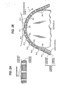
- the carrier sheet 25 comprises an inner layer 25a of lyophilic, or highly wettable material and a layer 25b of lyophobic, or less wettable material and is formed with a multitude of uniformly spaced apart, tiny throughbores 25c.
- the throughbores 25c have a diameter of 20 ⁇ m and are spaced a distance of 40 ⁇ m to 45 ⁇ m apart and the thickness of the carrier sheet 25 is 20 ⁇ m, so that the density is approximately 400 dots per inch.
- Suitable materials for the lyophilic layer 25a and lyophobic layer 25b are polyimide and fluororesin, such as polytetrafluoethylene (PTFE).
- the development liquid in the container 20 sticks to the lyophilic layer 25a and forms a thin layer 26a as it emerges above the liquid surface and is drawn upward to the electrode 24.
- the front edge of the drawn-up liquid layer 26a reaches an edge of the part-cylindrical contact surface of the electrode 24, it is squeezed between the contacting surfaces of the carrier sheet 25 and electrode 24 and forced to fill up the throughbores 25c.
- the pressure exerted on a given point of the liquid layer 26b increases as the carrier sheet is rotated clockwise until it reaches the point closest to the surface of the photoconductor layer 11.
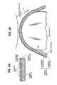
- a perforated carrier sheet 125 comprises an inner, porous layer 125a, such as polyurethane, and an outer lyophobic layer 125b which is formed with a multitude of throughbores 125c which extend down to the porous layer 125a.
- Porous layer 125a absorbs development liquid in the container 20, forming a development liquid layer 26a which is drawn up as shown in Fig. 4B by the carrier sheet 125 as it is rotated in the direction of arrow A and squeezing it between the inner layer 125a and the electrode 24. Due to the porosity of inner layer 125a, the squeezed development liquid is forced to permeate through it to the outer layer 125b.
- liquid columns build up in the throughbores 125c on the approaching portion of carrier sheet 125 to emerge from the surface of the layer 125b to increasing heights in the direction of rotation and those in the receding portion of the carrier sheet 125 decrease below the surface of layer 125b.
- the electrode 24 is described as being held stationary and having a hard conductive surface. However, to produce the pressure between the contact surfaces of the carrier sheet and electrode it is not necessary that the electrode 24 be stationary, but may be rotated at an appropriate speed in relation to the speed of rotation of the carrier sheet in a direction opposite to it, provided that the electrode 24 has a hard surface.
- Fig. 5 is modified embodiment of the present invention in which the apparatus includes a development station 215 which comprises a rotary electrode 224 and a perforated carrier sheet 225.
- rotary electrode 224 comprises a conductive rotary cylinder 224a and a conductive rubber layer 224b secured on the surface of the cylinder 224a.
- Cylinder 224a has a shaft 224c which is grounded and rotatably mounted on supports 200a of liquid container 200.
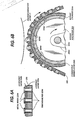
- Carrier sheet 225 is formed of a lyophilic layer 225a and a lyophobic layer 225b as in the carrier sheet of Fig. 2A and formed with a multitude of throughbores 225c.
- Meetal rings 225d are secured to the upper edge of corresponding throughbores 225c as shown in Fig. 6A.
- Carrier sheet 225 is supported between the rotary cylinder 224 and the submerged rotary cylinder 221 which is driven by motor 222.
- Conductive rubber layer 224b is sufficiently elastic so that portions 224d of its surface bulge outward into the bores 225c upon contact with the carrier sheet 225 as indicated in Fig. 6B, so that cylinder 224 and carrier sheet 225 rotate together at the same speed and liquid columns in the throughbores 225a on the approaching portion of carrier sheet 225 are pushed increasingly outward as it advances in the direction of arrow A, creating liquid bulges of increasing size. After emerging above the edge of metal rings, the liquid bulges tend to spread over the metal rings and swell due to the lyophilic characteristic of the rings 225d.
- Metal rings 225d have the effect of concentrating electrostatic fields to the edges of the individual throughbores 225c as well as to the liquid bulges therein.
- the concentration of fields facilitates the growth of those liquid bulges where the field is strongest and accelerates the transfer of liquid bulges to the photoconductor layer 11. Therefore, small liquid bulges can be adhered to the photoconductor surface. Images can be reproduced to fine details without undesired white blots in this manner.
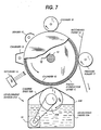
- FIG. 7 is an illustration of a further modification of the present invention.
- development station 315 includes a rotary electrode 324 which is grounded and supported by liquid container 320 so that it is partially submerged in development liquid 326 and rotatably driven by motor 322.
- a carrier sheet 325 of lyophobic material is held stationary between opposed edges of the container 320 in pressure contact with an upper, part-cylindrical surface of the rotary electrode 324.
- the contact area of carrier sheet 325 is perforated with a multitude of throughbores 325a.
- liquid 326 in the container is transported on the surface of rotary electrode 324 to the perforated area of carrier sheet 325 and squeezed therebetween, producting liquid bulges in a manner identical to those described in the previous embodiments.
- FIG. 10A A preferred form of the stationary carrier sheet is shown in Figs. 10A and 10B.
- a carrier sheet 425 is shown as comprising a lower lyophobic layer 425a which is perforated with bores 425b of a smaller diameter and an upper lyophilic layer 425c correspondingly perforated with bores 425d of a larger diameter, with the smaller diameter bores 425d being centered with the corresponding larger diameter bores 325b.
- Liquid squeezed under pressure into the lower, larger diamter bores 425b is forced into the upper, smaller diameter bores 425d with a pressure higher than it is forced into the lower bores 425b.
- a carrier sheet 525 is shown which is perforated with upwardly tapered throughbores 525a as illustrated in Fig. 10b.
- the rotary electrode 324 is preferably coated with a lyophilic layer 324a as shown in Fig. 11 to increase the amount of liquid drawn up to the carrier sheet.
Landscapes
- Physics & Mathematics (AREA)
- General Physics & Mathematics (AREA)
- Wet Developing In Electrophotography (AREA)
- Treatment Of Fiber Materials (AREA)
Applications Claiming Priority (12)
| Application Number | Priority Date | Filing Date | Title |
|---|---|---|---|
| JP65134/88 | 1988-03-17 | ||
| JP6513488A JPH01237581A (ja) | 1988-03-17 | 1988-03-17 | 液体現像装置 |
| JP65133/88 | 1988-03-17 | ||
| JP63065129A JPH01237578A (ja) | 1988-03-17 | 1988-03-17 | 液体現像装置 |
| JP6513388A JPH01237580A (ja) | 1988-03-17 | 1988-03-17 | 液体現像装置 |
| JP65129/88 | 1988-03-17 | ||
| JP18302688A JPH0232384A (ja) | 1988-07-21 | 1988-07-21 | 液体現像装置 |
| JP183026/88 | 1988-07-21 | ||
| JP20923288A JPH0256585A (ja) | 1988-08-22 | 1988-08-22 | 液体現像装置 |
| JP209232/88 | 1988-08-22 | ||
| JP23775088A JPH0284681A (ja) | 1988-09-21 | 1988-09-21 | 液体現像装置 |
| JP237750/88 | 1988-09-21 |
Publications (2)
| Publication Number | Publication Date |
|---|---|
| EP0333199A2 true EP0333199A2 (de) | 1989-09-20 |
| EP0333199A3 EP0333199A3 (de) | 1989-11-29 |
Family
ID=27551002
Family Applications (1)
| Application Number | Title | Priority Date | Filing Date |
|---|---|---|---|
| EP89104747A Ceased EP0333199A3 (de) | 1988-03-17 | 1989-03-16 | Gerät zum Nassentwicklen mit gelochtem Flüssigkeitstransportband |
Country Status (2)
| Country | Link |
|---|---|
| US (1) | US4942475A (de) |
| EP (1) | EP0333199A3 (de) |
Cited By (3)
| Publication number | Priority date | Publication date | Assignee | Title |
|---|---|---|---|---|
| WO1994022060A1 (en) * | 1993-03-23 | 1994-09-29 | Indigo N.V. | Liquid toner developing apparatus |
| EP0932087A3 (de) * | 1997-12-29 | 2000-07-12 | Brother Kogyo Kabushiki Kaisha | Bilderzeugungsgerät |
| EP0899623A3 (de) * | 1997-08-29 | 2001-04-18 | Brother Kogyo Kabushiki Kaisha | Bilderzeugungsapparat mit Flüssigentwickler |
Families Citing this family (5)
| Publication number | Priority date | Publication date | Assignee | Title |
|---|---|---|---|---|
| US4982692A (en) * | 1988-02-16 | 1991-01-08 | Nec Corporation | Apparatus for liquid development of electrostatic latent images |
| DE69529064T2 (de) * | 1994-02-08 | 2003-05-08 | Research Laboratories Of Australia Pty. Ltd., Eastwood | Mehrfarbenbilderzeugungsgerät mit flüssigentwicklung |
| US5561264A (en) * | 1994-10-07 | 1996-10-01 | Minolta Co., Ltd. | Liquid-type developing device |
| DE10027175A1 (de) * | 2000-05-31 | 2001-12-13 | Oce Printing Systems Gmbh | Applikatorelement und Verfahren zum elektrografischen Drucken oder Kopieren unter Verwendung flüssiger Farbmittel |
| JP2012091454A (ja) * | 2010-10-28 | 2012-05-17 | Canon Inc | 転写型インクジェット記録方法 |
Family Cites Families (9)
| Publication number | Priority date | Publication date | Assignee | Title |
|---|---|---|---|---|
| BE759027A (fr) * | 1969-11-17 | 1971-04-30 | Fuji Photo Film Co Ltd | Dispositif pour l'application d'un liquide sur la surface d'unefeuille |
| US4023898A (en) * | 1972-03-10 | 1977-05-17 | Research And Development Laboratories Of Ohno Co., Ltd. | Electrostatic developing apparatus |
| US3985437A (en) * | 1973-01-12 | 1976-10-12 | Coulter Information Systems, Inc. | Electrostatic image recording device having partially collapsible toner applicator |
| JPS5424643A (en) * | 1977-07-26 | 1979-02-24 | Canon Inc | Method and apparatus for liquid developing |
| JPS55159469A (en) * | 1979-05-30 | 1980-12-11 | Sharp Corp | Wet type developing device |
| US4400079A (en) * | 1980-09-24 | 1983-08-23 | Savin Corporation | Injection roller developer for electrophotographic copier and biasing system therefor |
| US4504138A (en) * | 1981-10-27 | 1985-03-12 | Coulter Systems Corporation | Method and apparatus for developing electrostatic latent images |
| US4410260A (en) * | 1981-12-09 | 1983-10-18 | Coulter Systems Corporation | Toning apparatus and method |
| US4493550A (en) * | 1982-04-06 | 1985-01-15 | Nec Corporation | Development apparatus of latent electrostatic images |
-
1989
- 1989-03-16 EP EP89104747A patent/EP0333199A3/de not_active Ceased
- 1989-03-17 US US07/324,863 patent/US4942475A/en not_active Expired - Fee Related
Cited By (3)
| Publication number | Priority date | Publication date | Assignee | Title |
|---|---|---|---|---|
| WO1994022060A1 (en) * | 1993-03-23 | 1994-09-29 | Indigo N.V. | Liquid toner developing apparatus |
| EP0899623A3 (de) * | 1997-08-29 | 2001-04-18 | Brother Kogyo Kabushiki Kaisha | Bilderzeugungsapparat mit Flüssigentwickler |
| EP0932087A3 (de) * | 1997-12-29 | 2000-07-12 | Brother Kogyo Kabushiki Kaisha | Bilderzeugungsgerät |
Also Published As
| Publication number | Publication date |
|---|---|
| US4942475A (en) | 1990-07-17 |
| EP0333199A3 (de) | 1989-11-29 |
Similar Documents
| Publication | Publication Date | Title |
|---|---|---|
| EP0078018B1 (de) | Verfahren und Vorrichtung zur Entwicklung elektrostatischer latenter Bilder | |
| CA1144821A (en) | Method and apparatus for liquid-developing latent electrostatic images | |
| US4493550A (en) | Development apparatus of latent electrostatic images | |
| EP0356164B1 (de) | Vorrichtung zur Flüssigtoner-Entfernung von einem Bildaufzeichnungsträger mittels Vakuum | |
| US4942475A (en) | Liquid development apparatus with perforated liquid carrier sheet | |
| EP0082428A1 (de) | Verfahren und Vorrichtung zur Entwicklung | |
| JP3702292B2 (ja) | 画像形成装置 | |
| US7079792B2 (en) | Developing unit using a developing liquid and image forming apparatus including the same | |
| US4982692A (en) | Apparatus for liquid development of electrostatic latent images | |
| CA1156879A (en) | Method and apparatus for developing latent electrostatic images | |
| EP0445208A1 (de) | Bilderzeugungsgerät basierend auf fliessendem entwickler und entwicklerelektrode dafür. | |
| JPH06138774A (ja) | 現像装置 | |
| CN1210995A (zh) | 记录装置 | |
| US5017968A (en) | Liquid development apparatus having comb-like electrode | |
| JP3702523B2 (ja) | 液体現像剤を用いた現像装置 | |
| KR100547104B1 (ko) | 고농도 잉크를 사용하는 습식 현상 장치 | |
| JPH09211993A (ja) | 液体現像剤を用いた現像装置 | |
| US3952702A (en) | Electrophotographic liquid toner development apparatus | |
| JPH09185266A (ja) | 液体現像剤を用いた現像装置 | |
| KR100322555B1 (ko) | 습식인쇄기의현상장치 | |
| US4693206A (en) | Self-seating toning shoe for electrostatic drum printers | |
| US6393240B1 (en) | Wet image forming apparatus with improved developer image | |
| JPH1020681A (ja) | 画像形成装置および画像形成方法 | |
| JP3236388B2 (ja) | 湿式画像形成装置 | |
| JPH09185265A (ja) | 液体現像剤を用いた現像装置 |
Legal Events
| Date | Code | Title | Description |
|---|---|---|---|
| PUAI | Public reference made under article 153(3) epc to a published international application that has entered the european phase |
Free format text: ORIGINAL CODE: 0009012 |
|
| 17P | Request for examination filed |
Effective date: 19890316 |
|
| AK | Designated contracting states |
Kind code of ref document: A2 Designated state(s): DE FR GB |
|
| PUAL | Search report despatched |
Free format text: ORIGINAL CODE: 0009013 |
|
| AK | Designated contracting states |
Kind code of ref document: A3 Designated state(s): DE FR GB |
|
| 17Q | First examination report despatched |
Effective date: 19920410 |
|
| STAA | Information on the status of an ep patent application or granted ep patent |
Free format text: STATUS: THE APPLICATION HAS BEEN REFUSED |
|
| 18R | Application refused |
Effective date: 19930719 |