EP0333203A2 - Vorrichtung zur Erzeugung bestimmter Beleuchtungsmuster - Google Patents
Vorrichtung zur Erzeugung bestimmter Beleuchtungsmuster Download PDFInfo
- Publication number
- EP0333203A2 EP0333203A2 EP89104772A EP89104772A EP0333203A2 EP 0333203 A2 EP0333203 A2 EP 0333203A2 EP 89104772 A EP89104772 A EP 89104772A EP 89104772 A EP89104772 A EP 89104772A EP 0333203 A2 EP0333203 A2 EP 0333203A2
- Authority
- EP
- European Patent Office
- Prior art keywords
- rod shaped
- optical axis
- linear light
- longitudinal direction
- prescribed
- Prior art date
- Legal status (The legal status is an assumption and is not a legal conclusion. Google has not performed a legal analysis and makes no representation as to the accuracy of the status listed.)
- Granted
Links
Images





Classifications
-
- G—PHYSICS
- G02—OPTICS
- G02B—OPTICAL ELEMENTS, SYSTEMS OR APPARATUS
- G02B6/00—Light guides; Structural details of arrangements comprising light guides and other optical elements, e.g. couplings
- G02B6/24—Coupling light guides
- G02B6/42—Coupling light guides with opto-electronic elements
- G02B6/4201—Packages, e.g. shape, construction, internal or external details
- G02B6/4204—Packages, e.g. shape, construction, internal or external details the coupling comprising intermediate optical elements, e.g. lenses, holograms
- G02B6/4206—Optical features
-
- G—PHYSICS
- G02—OPTICS
- G02B—OPTICAL ELEMENTS, SYSTEMS OR APPARATUS
- G02B5/00—Optical elements other than lenses
- G02B5/02—Diffusing elements; Afocal elements
- G02B5/0205—Diffusing elements; Afocal elements characterised by the diffusing properties
- G02B5/021—Diffusing elements; Afocal elements characterised by the diffusing properties the diffusion taking place at the element's surface, e.g. by means of surface roughening or microprismatic structures
- G02B5/0215—Diffusing elements; Afocal elements characterised by the diffusing properties the diffusion taking place at the element's surface, e.g. by means of surface roughening or microprismatic structures the surface having a regular structure
-
- G—PHYSICS
- G02—OPTICS
- G02B—OPTICAL ELEMENTS, SYSTEMS OR APPARATUS
- G02B6/00—Light guides; Structural details of arrangements comprising light guides and other optical elements, e.g. couplings
- G02B6/0001—Light guides; Structural details of arrangements comprising light guides and other optical elements, e.g. couplings specially adapted for lighting devices or systems
- G02B6/0005—Light guides; Structural details of arrangements comprising light guides and other optical elements, e.g. couplings specially adapted for lighting devices or systems the light guides being of the fibre type
- G02B6/001—Light guides; Structural details of arrangements comprising light guides and other optical elements, e.g. couplings specially adapted for lighting devices or systems the light guides being of the fibre type the light being emitted along at least a portion of the lateral surface of the fibre
-
- G—PHYSICS
- G02—OPTICS
- G02B—OPTICAL ELEMENTS, SYSTEMS OR APPARATUS
- G02B6/00—Light guides; Structural details of arrangements comprising light guides and other optical elements, e.g. couplings
- G02B6/0001—Light guides; Structural details of arrangements comprising light guides and other optical elements, e.g. couplings specially adapted for lighting devices or systems
Definitions
- the present invention relates to a rod shaped linear light diffusion apparatus for diffusing incidental light and, more specifically, to a rod shaped linear light diffusion apparatus capable of providing desired luminous fluxes.
- FIG. 1A is a schematic diagram showing a structure of such a conventional rod shaped linear light diffusion apparatus.
- the conventional rod shaped linear light diffusion apparatus 1 comprises a rod 2 for transmitting light emitted from a light source 4 through a reflecting plate 5 and for diffusing the light at desired portions, a diffused reflection layer 3 formed on the surface of the rod 2 and a reflecting mirror 6 provided on an end portion opposing to the light entering side of the rod 2.
- the diffused reflection layer 3 is formed by coating the surface of the rod 2 with a silicon rubber including suspended white minute powder of a material having high refractive index such as titanium, potassium titanate or zinc oxide.
- the light transmitted from one end of the rod 2 is diffused when it encounters to the diffused reflection layer 3.
- By appropriately thickening the diffused reflection layer 3, most of the light is diffused to the inside of the rod 2.
- the light transmitted without encountering the diffused reflection layer 3 is reflected by the reflecting mirror 6 provided at the end of the rod 2 to be returned to the inlet side of the rod 2.
- Fig. 1B is a cross sectional view of a portion taken along the line IB-IB of the rod 2 shown in Fig. 1A.
- Luminous fluxes which have reached the diffused reflection layer 3 are irregularly reflected.
- a luminous flux 1 incident to the periphery of the rod 2 with an angle larger than a critical angle is totally reflected at the periphery of the rod and it is continuously reflected in the rod 2 until it encounters the diffused reflection layer 3 again. Meanwhile, luminous fluxes incident to the periphery of the rod 2 at an angle smaller than the critical angle are refracted at the periphery to be radiated externally, so that luminous fluxes having directivity are emitted from the rod 2.
- Fig. 2A is a perspective view of a main portion of the facsimile to which the rod shaped linear light diffusion apparatus disclosed in the aforementioned patent is applied.
- the application of the rod shaped linear light diffusion apparatus, which can be used as the above mentioned linear light source, is not limited to the linear light source of a copying machine, facsimile or the like.
- Fig. 2B shows another application of the rod shaped linear light diffusion apparatus 1 used as the linear light source.
- the rod shaped linear light diffusion apparatus 1 used as a linear light source may be used as an illuminating apparatus such as a table lamp, floor lamp, ceiling lamp etc. when it is connected to an ordinary light source even, for example, solar radiation.
- the rod shaped linear light diffusion apparatus 1 used as a linear light source has superior advantages of little heat radiation, approximately uniform distribution of intensity of irradiation over the longitudinal direction of the rod and ready maintenance such as readiness in changing the rod and the like. However, it has a disadvantage of low efficiency of irradiation as the luminous fluxes emitted therefrom are dispersed, as shown in Fig. 1B.
- Fig. 3 shows a cylindrical condenser lens 16 provided behind the rod shaped linear light diffusing apparatus 1 to solve the above described problem.
- the dispersed luminous fluxes are condensed.
- the luminous fluxes emitted from the rod shaped linear light diffusing apparatus 1 are not radiated from one point.
- each optical path intersects with the optical axis at different points. Therefore, the luminous fluxes cannot be converged to one point by means of the cylindrical lens 16.
- a region to be irradiated is not linear but wide in a direction orthogonal to the axis of the rod shaped linear light diffusion apparatus, it is desired that a constant illuminance is maintained regardless of the change of distance between the surface to be irradiated and the rod shaped linear light diffusion apparatus 1.
- the luminous fluxes radiated from the rod shaped linear light diffusion apparatus 1 must be made parallel fluxes.
- the illuminance of the luminous fluxes radiated from the conventional rod shaped linear light diffusion apparatus 1 is higher at the central portion and lower at the opposing end portions. Namely, the distribution of illuminance is not uniform. Therefore, a region having a prescribed area cannot be uniformly illuminated.
- one object of the present invention is to provide desired luminous fluxes in a rod shaped linear light diffusion apparatus.
- Another object of the present invention is to provide luminous fluxes which can be linearly condensed in a rod shaped linear light diffusion apparatus.
- a further object of the present invention is to provide parallel fluxes in a transparent rod shaped linear light diffusion apparatus.
- a still further object of the present invention is to make uniform the distribution of illuminance in a transparent rod shaped linear light diffusion apparatus.
- a rod shaped linear light diffusion apparatus in accordance with the present invention, comprising: a cylindrical member extending in a longitudinal direction for transmitting incident light to said longitudinal direction, the cylindrical member having one end and the other end provided in the longitudinal direction, the incident light entering from the said one end; a reflecting member provided on the said the other end of the cylindrical member for reflecting the incident light; a irregular reflection member formed aligned with the longitudinal direction of the cylindrical member for irregularly reflecting the incident light, in a cross sectional direction intersecting the longitudinal direction, a direction passing through a center of the circle forming the cylindrical member and a position at which the diffused reflection member is formed defining the direction of the optical axis of the cylindrical member; and a diffusing member formed on an opposite side of the diffusion reflecting member about the center in the cross sectional direction and on the outer periphery of the cylindrical member aligned with the longitudinal direction for diffusing the irregularly reflected light to a direction having a prescribed relation between the direction of the optical axis.
- the rod shaped linear light diffusion apparatus comprises the above described components, the incident light entering from the longitudinal direction is diffused to a direction having a prescribed relation with the direction of the optical axis intersecting the longitudinal direction, and the direction having the prescribed relation can be arbitrarily selected. Therefore, desired luminous fluxes can be obtained in the rod shaped linear light diffusion apparatus.
- the diffusing member comprises a plurality of saw tooth shaped grooves and the plurality of saw tooth shaped grooves are formed such that the diffused light are refracted in a direction toward a prescribed one point. Therefore, the diffused reflected light is linearly condensed along the longitudinal direction at a position on the optical axis spaced apart by a prescribed distance from the rod shaped linear light diffusion apparatus. Consequently, luminous fluxes which can be linearly condensed can be provided by the rod shaped linear light diffusion apparatus.
- the plurality of saw tooth shaped grooves are formed such that the diffused light are diffused in parallel in the axial direction. Therefore, the diffused reflected light is diffused in parallel to the direction of the optical axis of the rod shaped linear light diffusion apparatus. Consequently, parallel luminous fluxes can be obtained by a rod shaped linear light diffusion apparatus.
- the light diffused by the diffusing member is used as an illuminating light having a prescribed illuminance, and the plurality of saw tooth shaped grooves are formed such that the illuminance of the diffused light on a surface intersecting the optical axis is made uniform. Therefore, the diffused reflected light has a constant illuminance on a surface intersecting the optical axis of the rod shaped linear light diffusion apparatus. Consequently, the distribution of illuminance can be made uniform in a rod shaped linear light diffusion apparatus.
- the desired luminous fluxes in accordance with the present invention comprises luminous fluxes which can be linearly condensed, parallel fluxes, and luminous fluxes capable of providing uniform distribution of illuminance.
- the rod shaped linear light diffusion apparatuses capable of providing respective luminous fluxes will be described in the following.
- the transparent rod shaped linear light diffusion apparatus capable of linear condensing of the light in accordance with the present invention comprises three preferable embodiments.
- Fig. 4 shows a first embodiment of the transparent rod shaped linear light diffusion apparatus capable of linearly condensing light in accordance with the present invention, which corresponds to Fig. 1B.
- a diffused reflection layer 3 is formed at the point E on the outer periphery of the rod 2 and a plurality of saw tooth shaped grooves 11 are formed on the peripheral surface opposing to the diffused reflection layer 3 of the rod 2.
- a plurality of saw tooth shaped grooves are formed on the outer periphery of the rod in Fig. 4, it is not necessary for the grooves to be formed on the outer periphery of the rod.
- a member with a plurality of saw tooth shaped grooves can be attached to a member with a prism section, thereby to form a rod with a plurality of saw tooth shaped grooves.
- the light reflected at the point E at the outer peripheral surface of the rod 2 is diffused in a prescribed direction by the saw tooth shaped grooves 1 to be condensed on the point B on an X axis passing through the center O of the rod 2.
- the reference character b represents a distance from the center O of the rod 2 to the condensing point B and the reference character r represents the radius of the rod 2.
- a plurality of saw tooth shaped grooves are formed along the longitudinal direction of the rod 2 at the peripheral surface of the rod 2 opposing to the point E. However, only one groove 11 is shown in Fig. 5 for the purpose of facilitating understanding of the principle.
- point A an intersection of a normal of a CD surface at the point of C and the X axis, with the coordinate value being (a, 0)
- point B an intersection of a refracted luminous flux and the X axis with the coordinate value being (b, 0)
- point C refracting point of the luminous flux
- CD surface of the groove 11
- ⁇ angle of the luminous flux reflected from the point E with the X axis
- ⁇ incident angle of the luminous flux at the CD surface
- ⁇ angle of irradiation of the luminous flux at the CD surface
- n refractive index of the rod
- the angle ⁇ of the surface of each of the saw tooth shaped grooves 11 by which the value of the distance b is made constant can be determined from the angle of reflection ⁇ of the luminous flux from the point E, the refractive index n of the rod 2, the radius r of the rod and the distance b to the point of condensing the luminous flux. If the grooves 11 are formed at the positions determined by the angle ⁇ , the luminous fluxes reflected from the point E are all condensed to the point B on the X axis as shown in Fig. 4, whereby a rod shaped linear light diffusion apparatus illuminating a linear region can be provided. In the embodiment shown in Fig.
- the increment of the angle ⁇ may be arbitrarily set at smaller value as needed.
- the linear condensing of light is effected by forming the rod with a material having the refractive index higher than 2.
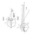
- Fig. 6 is a cross sectional view showing light paths of a transparent rod shaped linear light diffusion apparatus 1 formed of a material having the refractive index of 2. Referring to Fig. 6, the light reflected by the diffused reflection layer 3 formed on a point E at the outer peripheral surface of the rod 10 is reflected on the outer peripheral surface of the rod 10, and the reflected light is converged on the X axis passing through the center O of the rod 10 at some distance from the center O.
- Fig. 7 illustrates the reason why the luminous fluxes are condensed by the rod 10 formed of a material having the refractive index of 2 such as shown in Fig. 6.
- Fig. 7 shows a transparent rod 2 having a circular cross section of a radius R.
- the light is reflected at the angle of ⁇ with the axis X from an intersecting point E of the X axis and the periphery, and the light is refracted at the point C and intersects with the X axis at the point B.
- the equation is always capable of being established regardless of the value of ⁇ .
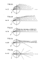
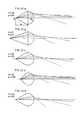
- Figs. 8A to 8E show optical paths when the rods are formed of transparent materials having different refractive indices n.
- n the luminous fluxes reflected from the linear diffused reflection layer 3 on the peripheral surface are diffused.
- the luminous fluxes are tend to be condensed, and when n ⁇ 2, the luminous fluxes are condensed to a narrow range.
- a cylindrical rod may be formed with a transparent material whose refractive index (n) is higher than 2. Examples of such materials having high refractive indices and the wavelength of the light are shown in the following table.
- optical transmission range measuring light ( ⁇ m) refractive index ( ⁇ m) FDS10(HOYA) 0.42 - 2 0.486 0.02 optical glass 0.656 1.97 PbM0O4 lead molybdate 0.42 - 5.5 0.633 2.37 TeO2 tellurium dioxide 0.35 - 5 0.633 2.26 LiNbO3 lithium niobate 0.4 - 0.5 0.633 2.20 Ge germanium 2 - 20 2.48 4.08 ZrO2-Y2O3 firenite 0.5 - 6 0.633 2.17 Si silicon 1 - 15 3.50
- FDS10(HOYA) may be used as a material having the refractive index of 2
- PbM0O4 and TeO2 may be used as the materials having the refractive index higher than 2
- Ge may be used as a material having the refractive index of 4.
- Ge transmits light of the infrared region having the wavelength of 2 to 20 ⁇ m. Therefore, by condensing the infrared light by means of a cylindrical rod formed of germanium, the cylindrical rod may be used as a linear heat source.
- the cross sectional shape of the rod is not a perfect circle but a combination of a triangle and a semicircle, as shown in Fig. 9.
- the distance a between the center O of the semicircular portion and the linear diffused reflection layer E serving as a light emitting portion is selected to be larger than the radius R of the semicircular portion.
- condensing luminous fluxes can be provided by using a conventional rod formed of a transparent material having lower refractive index.
- Fig. 9 shows a cross section of a rod 13 which is, in the right side of the Y axis, a semicircle having the radius of R and in the left side an isosceles triangle whose vertex is a point F (coordinate value: (-a, 0)) which is spaced apart from the center O by a distance (a)(a > r).
- the angle of reflection from the point F with the X axis is represented by ⁇
- the intersecting point of the optical path of the light beam refracted at the point C on the peripheral surface of the semicircle with the X axis is represented by B
- the incident angle at the point C is represented by ⁇
- the angle of irradiation is represented by ⁇
- the angle of intersection of the refracted light with the X axis is represented by ⁇
- ⁇ ⁇ must be no less than zero ( ⁇ 0) in order to make the value sin ⁇ ⁇ 0.
- Figs. 10A to 10E schematically show optical paths when the refractive index n of the rod and the distance a between the center of the rod and the light emitting portion are variously changed. In these examples, the luminous fluxes are not linearly condensed.
- the respective rods shown in Figs. 10A to 10E may be utilized as linear light sources for illuminating a region of a prescribed with.
- n and a By appropriately selecting the values of n and a , the distribution of illuminance of the rods in the width region to be irradiated can be adapted to meet the desired conditions.
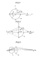
- Fig. 11 illustrates a third embodiment of the present invention in which a rod 2 with a portion of the cylinder cut and a condenser lens 17 such as a cylindrical lens or a linear Fresnel lens are arranged adjacent to each other on an optical axis.
- the luminous fluxes refracted at the diffused reflection layer 3 formed at the portion represented by G of the rod 2 are condensed by the condenser lens 17 to be condensed on the point B of the optical axis of the condenser lens 17.
- the light reflected from the point G must be diffused from one point K on a line passing through the points O-G, as shown by the dotted lines in Fig. 12.
- the position G of the diffused reflection layer must be set at a distance R/n from the center O. The reason for this will be described in the following.
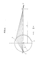
- Fig. 13A is a cross sectional view of a cylindrical rod having a refractive index of n and a radius of R.
- the line KP can be represented by the following equation.
- Y tan( ⁇ + ⁇ - ⁇ ) ⁇ X - Rcos( ⁇ + ⁇ ) ⁇ + Rsin( ⁇ + ⁇ ) (9)
- the coordinate of the point K, where the line KP intersects with the X axis, from the origin (O) is "-nR". This does not include the angle ⁇ of the luminous flux with the X axis, so that the position of the point K is constant. More specifically, the optical paths of the light beams which are reflected from the point G and refracted at the peripheral surface of the rod 20 to be emitted are all converged to the point K.
- illuminance of the transparent rod shaped linear light diffusion apparatus incorporating such a cylindrical lens will be described in the following. Referring to Fig. 13B, let us consider the illuminance on a surface (represented as a line in the figure) which is vertical to the X axis and passes through the point M on the X axis.
- the illuminance is proportional to the optical energy incident to a unit area
- the illuminance is proportional to ( ⁇ / ⁇ h) (where ⁇ is an increment of the angle ⁇ corresponding to ⁇ h).
- this rod shaped linear light diffusion apparatus has superior characteristic as a surface light source.
- the refractive index n of the transparent material constituting the cylindrical rod is no less than ⁇ 3
- the cylindrical rod is cut at a flat surface which is spaced apart from the central line by the distance of R/n and a linear diffused reflection layer is formed at the center thereof in the above described embodiment, the cross sectional shape of the rod may be changed.
- the cross section may be a combination of a semicircle having the diameter of R in the right side of the Y axis and an isosceles triangle in the left side in which opposing ends in the Y axis of the semicircles and a point G which is spaced apart from the center O by the distance R/n are connected, and the diffused reflection layer may be provided at the point G, as shown in Fig. 14A.
- the cross section may comprise a curve connecting the point G with the opposing ends in the Y axis of the semicircle as shown in Fig. 14B.
- the semicircle in the right side and the triangle or the oval portion in the left side may be separately manufactured and thereafter they may be attached to each other by means of Canada Balsam or the like.
- Fig. 15 illustrates an application of the first embodiment for linearly condensing light, in which the irregularly reflected light from the diffused reflecting layer 3 of the rod 12 are made parallel beams by means of the saw tooth shaped grooves 11.
- the luminous fluxes reflected at the point E will be parallel luminous fluxes in the direction of the X axis as shown in Fig. 15.
- the increment of the angle can be arbitrarily set to be smaller.
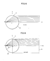
- Figs. 16 and 17 show other applications of the transparent rod shaped linear light diffusion apparatus capable of linearly condensing light shown in the first embodiment, providing luminous fluxes whose distribution of illuminance is uniform.
- Fig. 18 illustrates a principle of illumination of the surface shown in Figs. 16 and 17 with uniform distribution of illuminance.
- Fig. 18 is a cross sectional view of a cylindrical rod 22 having a radius of R formed of a transparent material having the refractive index of n as in the above described embodiment in Fig. 5.
- luminous fluxes incident to the end surface of the rod 22 are dispersed by a diffused reflection layer formed at the point E on the outer peripheral surface on the X axis.
- a plurality of saw tooth shaped grooves 23 are provided parallel to each other along the longitudinal direction.
- the point O represents a linear light source which is long enough in a direction vertical to the plane of the drawing.
- SL represents a surface to be illuminated positioned at a distance S from the point O. It is assumed that the linear light source emits light uniformly in all directions.
- the illuminance at the surface SL is uniform at any cross section in the direction vertical to the plane of the drawing, so that we may consider the illuminance on a segment SL at an arbitrary cross section.
- the illuminance at the point L is inversely proportional to the distance from the light source and is directly proportional to the cosine (cos) of the angle of the normal of the surface SL at the point L with the luminous flux.
- the illuminance at the point L is directly proportional to d ⁇ /dh.
- the angle ⁇ of the normal AC of the surface CD of the saw tooth shaped groove 23 with the X axis at a point where the luminous flux reflected from the point E with the angle ⁇ can be determined.
- the surface 14 to be illuminated which is vertical to the X axis can be illuminated with the uniform distribution of illuminance at a position spaced from the center O of the rod 22 by the distance m.
- the factor of the distance m of irradiation at the equation (26) is included in the data of the angle ⁇ shown in the equation (25).
- Figs. 16 and 17 are cross sectional views showing embodiments of the transparent rod shaped linear light diffusion apparatus illuminating a surface to be illuminated with uniform distribution of illuminance, based on the above described theory.
- the increment of the angle of the luminous flux reflected from the point E is 5°.
- the angle of the surface of the saw tooth shaped groove 23 formed on the surface from which the luminous fluxes are emitted is set based on the above described equation.
- the luminous fluxes reflected from the point E with equal increment of angle are projected on the surface to be illuminated 14 with a constant pitch. Therefore, uniform distribution of illuminance can be provided in the direction of the Y axis.
- the increment of the angle of the luminous flux reflected from the point E is selected to be 5°. By setting smaller increment, the uniformity of the distribution of illuminance can be further improved.
- the rod is formed of a soft material such as an acrylic resin
- a plurality of saw tooth shaped grooves can be provided on the peripheral surface of the transparent rod along the longitudinal direction by means of a diamond tool.
- a flat plate of an acrylic resin may be applied on the peripheral surface of the rod and the grooves are formed in the plate.
- a transparent rod shaped linear light diffusion apparatus can be provided by making the cross sectional shape of the rod constituting the transparent rod shaped linear light diffusion apparatus saw tooth shape or a circle with a portion eliminated by a prescribed ratio or by forming the transparent rod with a material having a prescribed refractive index.
- the transparent rod shaped linear light diffusion apparatus in accordance with the foregoing embodiments of the present invention when used, no auxiliary optical system such as a cylindrical lens is required, so that the structure of a copying machine, a facsimile or a scanner such as a line sequential image scanner can be made simple and compact.
- the transparent rod shaped linear light diffusion apparatus of the present invention can be used as a general illuminating apparatus to provide desired illumination.
Landscapes
- Physics & Mathematics (AREA)
- General Physics & Mathematics (AREA)
- Optics & Photonics (AREA)
- Facsimile Scanning Arrangements (AREA)
- Planar Illumination Modules (AREA)
- Light Sources And Details Of Projection-Printing Devices (AREA)
- Light Guides In General And Applications Therefor (AREA)
Applications Claiming Priority (6)
| Application Number | Priority Date | Filing Date | Title |
|---|---|---|---|
| JP63400/88 | 1988-03-18 | ||
| JP6340088A JPH0754399B2 (ja) | 1988-03-18 | 1988-03-18 | 透明ロッド光源装置 |
| JP82323/88 | 1988-04-05 | ||
| JP8232388A JPH0672963B2 (ja) | 1988-04-05 | 1988-04-05 | 透明ロッド光源装置 |
| JP63083127A JPH0782127B2 (ja) | 1988-04-06 | 1988-04-06 | 透明ロッド光源装置 |
| JP83127/88 | 1988-04-06 |
Publications (3)
| Publication Number | Publication Date |
|---|---|
| EP0333203A2 true EP0333203A2 (de) | 1989-09-20 |
| EP0333203A3 EP0333203A3 (de) | 1991-07-03 |
| EP0333203B1 EP0333203B1 (de) | 1995-06-14 |
Family
ID=27298159
Family Applications (1)
| Application Number | Title | Priority Date | Filing Date |
|---|---|---|---|
| EP89104772A Expired - Lifetime EP0333203B1 (de) | 1988-03-18 | 1989-03-17 | Vorrichtung zur Erzeugung bestimmter Beleuchtungsmuster |
Country Status (3)
| Country | Link |
|---|---|
| US (1) | US4941723A (de) |
| EP (1) | EP0333203B1 (de) |
| DE (1) | DE68923020T2 (de) |
Cited By (9)
| Publication number | Priority date | Publication date | Assignee | Title |
|---|---|---|---|---|
| EP0426433A3 (en) * | 1989-10-30 | 1991-08-28 | Minnesota Mining And Manufacturing Company | Light fixture for externally illuminated sign |
| WO1993010394A1 (en) * | 1991-11-22 | 1993-05-27 | Tir Systems Ltd. | Lighting structure having variable transmissivity internal light guide illumination |
| DE4329914A1 (de) * | 1993-09-04 | 1995-03-09 | Willing Gmbh Dr Ing | Linearer Lichtleiter |
| WO1998020279A1 (en) * | 1996-11-07 | 1998-05-14 | Minnesota Mining And Manufacturing Company | Light-illuminating rods |
| WO2000077447A1 (en) * | 1999-06-15 | 2000-12-21 | Leonardo Masotti | Continuous extended optical sources and receivers and optical barriers using said sources and said receivers |
| DE10032158A1 (de) * | 2000-07-01 | 2002-01-10 | Hella Kg Hueck & Co | Stabförmiger Lichtleiter |
| US6366727B1 (en) | 1996-11-07 | 2002-04-02 | 3M Innovative Properties Company | Light-illuminating rods |
| US6606439B2 (en) | 1999-04-08 | 2003-08-12 | 3M Innovative Properties Company | Light-illuminating rods |
| EP1154198A3 (de) * | 2000-05-10 | 2004-05-06 | Hella KG Hueck & Co. | Stabförmiger Lichtleiter |
Families Citing this family (11)
| Publication number | Priority date | Publication date | Assignee | Title |
|---|---|---|---|---|
| US5080706A (en) * | 1990-10-01 | 1992-01-14 | The United States Of America As Represented By The Department Of Energy | Method for fabrication of cylindrical microlenses of selected shape |
| US5257340A (en) * | 1992-06-01 | 1993-10-26 | Eastman Kodak Company | Linear coated core/clad light source/collector |
| US5717455A (en) * | 1996-07-02 | 1998-02-10 | Raax Co., Ltd. | System and method for three dimensional image acquisition and processing of a borehole wall |
| DE19740265A1 (de) * | 1997-09-12 | 1999-03-18 | Willing Gmbh Dr Ing | Seitlich lichtabstrahlender Lichtleiter |
| AU2001243474A1 (en) | 2000-03-06 | 2001-09-17 | Teledyne Lighting And Display Products, Inc. | Led light source with field-of-view-controlling optics |
| US6744960B2 (en) | 2000-03-06 | 2004-06-01 | Teledyne Lighting And Display Products, Inc. | Lighting apparatus having quantum dot layer |
| US6637924B2 (en) | 2000-11-15 | 2003-10-28 | Teledyne Lighting And Display Products, Inc. | Strip lighting apparatus and method |
| US6784603B2 (en) * | 2001-07-20 | 2004-08-31 | Teledyne Lighting And Display Products, Inc. | Fluorescent lighting apparatus |
| US7048424B2 (en) * | 2002-08-14 | 2006-05-23 | Cross Match Technologies, Inc. | Light integrating column |
| US7330632B1 (en) | 2006-08-23 | 2008-02-12 | Energy Focus, Inc. | Fiberoptic luminaire with scattering and specular side-light extractor patterns |
| JP5582981B2 (ja) * | 2010-11-18 | 2014-09-03 | 株式会社小糸製作所 | 導光部材 |
Family Cites Families (10)
| Publication number | Priority date | Publication date | Assignee | Title |
|---|---|---|---|---|
| DE1959740A1 (de) * | 1969-11-28 | 1971-06-03 | Licentia Gmbh | Streifenfoermige Lichtquelle |
| DE2508366C3 (de) * | 1975-02-26 | 1979-05-17 | Erwin Sick Gmbh Optik-Elektronik, 7808 Waldkirch | Optische Vorrichtung mit einem Lichtvorhang |
| US4108540A (en) * | 1976-06-17 | 1978-08-22 | Minnesota Mining And Manufacturing Company | Refractor-reflector radiation concentrator |
| US4099535A (en) * | 1977-02-22 | 1978-07-11 | Hubachek Louis H | Light emitting walking cane |
| CH633381A5 (de) * | 1978-12-20 | 1982-11-30 | Bbc Brown Boveri & Cie | Elektrooptische anzeige mit reflektor. |
| JPS5763321U (de) * | 1980-09-30 | 1982-04-15 | ||
| US4535240A (en) * | 1983-09-23 | 1985-08-13 | Vigurs John P C | Intruder detection |
| US4561043A (en) * | 1984-09-27 | 1985-12-24 | Thompson Gary J | Decorative light display |
| CA1268969A (en) * | 1986-01-15 | 1990-05-15 | Sanford Cobb, Jr. | Totally internally reflecting light conduit |
| US4797711A (en) * | 1986-09-10 | 1989-01-10 | Dainippon Screen Mfg., Co., Ltd. | Image scanning apparatus |
-
1989
- 1989-03-15 US US07/324,399 patent/US4941723A/en not_active Expired - Fee Related
- 1989-03-17 EP EP89104772A patent/EP0333203B1/de not_active Expired - Lifetime
- 1989-03-17 DE DE68923020T patent/DE68923020T2/de not_active Expired - Fee Related
Cited By (9)
| Publication number | Priority date | Publication date | Assignee | Title |
|---|---|---|---|---|
| EP0426433A3 (en) * | 1989-10-30 | 1991-08-28 | Minnesota Mining And Manufacturing Company | Light fixture for externally illuminated sign |
| WO1993010394A1 (en) * | 1991-11-22 | 1993-05-27 | Tir Systems Ltd. | Lighting structure having variable transmissivity internal light guide illumination |
| DE4329914A1 (de) * | 1993-09-04 | 1995-03-09 | Willing Gmbh Dr Ing | Linearer Lichtleiter |
| WO1998020279A1 (en) * | 1996-11-07 | 1998-05-14 | Minnesota Mining And Manufacturing Company | Light-illuminating rods |
| US6366727B1 (en) | 1996-11-07 | 2002-04-02 | 3M Innovative Properties Company | Light-illuminating rods |
| US6606439B2 (en) | 1999-04-08 | 2003-08-12 | 3M Innovative Properties Company | Light-illuminating rods |
| WO2000077447A1 (en) * | 1999-06-15 | 2000-12-21 | Leonardo Masotti | Continuous extended optical sources and receivers and optical barriers using said sources and said receivers |
| EP1154198A3 (de) * | 2000-05-10 | 2004-05-06 | Hella KG Hueck & Co. | Stabförmiger Lichtleiter |
| DE10032158A1 (de) * | 2000-07-01 | 2002-01-10 | Hella Kg Hueck & Co | Stabförmiger Lichtleiter |
Also Published As
| Publication number | Publication date |
|---|---|
| EP0333203B1 (de) | 1995-06-14 |
| DE68923020D1 (de) | 1995-07-20 |
| EP0333203A3 (de) | 1991-07-03 |
| DE68923020T2 (de) | 1995-11-02 |
| US4941723A (en) | 1990-07-17 |
Similar Documents
| Publication | Publication Date | Title |
|---|---|---|
| EP0333203A2 (de) | Vorrichtung zur Erzeugung bestimmter Beleuchtungsmuster | |
| US4750798A (en) | Prism light guide luminaire | |
| CA1215957A (en) | Prism light guide luminaire | |
| US5668913A (en) | Light expanding system for producing a linear or planar light beam from a point-like light source | |
| US5521725A (en) | Illumination system employing an array of microprisms | |
| JP3303868B2 (ja) | 光学的に透明なフィルム | |
| US6129439A (en) | Illumination system employing an array of multi-faceted microprisms | |
| CA2358104C (en) | A backlight for correcting diagonal line distortion | |
| US5739931A (en) | Illumination system employing an array of microprisms | |
| US4791540A (en) | Light fixture providing normalized output | |
| KR100801227B1 (ko) | 백라이트 | |
| US6102552A (en) | Laser-array based digital illuminator | |
| US7817909B2 (en) | Optical device and light source | |
| US6697042B1 (en) | Backlight assembly for collimated illumination | |
| JP3532212B2 (ja) | 多面微小プリズム列を採用した照射装置 | |
| KR20080077190A (ko) | 얇고 효율적인 광 콜리메이션 장치, 발광 장치 및디스플레이 장치 | |
| EP0467608A2 (de) | Katadioptrische Linse mit gleichmässigem Intensitätsprofil | |
| US7631991B2 (en) | Brightness enhancement of LED using selective ray angular recycling | |
| JPS5821702A (ja) | 微小幅両面反射帯を用いた結像素子 | |
| KR970022488A (ko) | 개선된 투사 스크린 및 그 동등물 | |
| Saxe et al. | Progress in the development of prism light guides | |
| EP0483952A2 (de) | Laserlicht-Wellenlängenwandler | |
| JPH1139914A (ja) | 平面照明装置とその装置の光透過部の製造方法 | |
| JPH11133208A (ja) | 面光源変換用光学素子 | |
| KR910009730B1 (ko) | 내부반사 도과형 집광렌즈(內部反射 導過型 集光 lens) |
Legal Events
| Date | Code | Title | Description |
|---|---|---|---|
| PUAI | Public reference made under article 153(3) epc to a published international application that has entered the european phase |
Free format text: ORIGINAL CODE: 0009012 |
|
| AK | Designated contracting states |
Kind code of ref document: A2 Designated state(s): DE FR GB IT |
|
| PUAL | Search report despatched |
Free format text: ORIGINAL CODE: 0009013 |
|
| AK | Designated contracting states |
Kind code of ref document: A3 Designated state(s): DE FR GB IT |
|
| 17P | Request for examination filed |
Effective date: 19911112 |
|
| 17Q | First examination report despatched |
Effective date: 19930128 |
|
| GRAA | (expected) grant |
Free format text: ORIGINAL CODE: 0009210 |
|
| AK | Designated contracting states |
Kind code of ref document: B1 Designated state(s): DE FR GB IT |
|
| PG25 | Lapsed in a contracting state [announced via postgrant information from national office to epo] |
Ref country code: IT Free format text: LAPSE BECAUSE OF FAILURE TO SUBMIT A TRANSLATION OF THE DESCRIPTION OR TO PAY THE FEE WITHIN THE PRESCRIBED TIME-LIMIT;WARNING: LAPSES OF ITALIAN PATENTS WITH EFFECTIVE DATE BEFORE 2007 MAY HAVE OCCURRED AT ANY TIME BEFORE 2007. THE CORRECT EFFECTIVE DATE MAY BE DIFFERENT FROM THE ONE RECORDED. Effective date: 19950614 Ref country code: FR Effective date: 19950614 |
|
| REF | Corresponds to: |
Ref document number: 68923020 Country of ref document: DE Date of ref document: 19950720 |
|
| EN | Fr: translation not filed | ||
| PLBE | No opposition filed within time limit |
Free format text: ORIGINAL CODE: 0009261 |
|
| STAA | Information on the status of an ep patent application or granted ep patent |
Free format text: STATUS: NO OPPOSITION FILED WITHIN TIME LIMIT |
|
| 26N | No opposition filed | ||
| PGFP | Annual fee paid to national office [announced via postgrant information from national office to epo] |
Ref country code: GB Payment date: 19980309 Year of fee payment: 10 |
|
| PGFP | Annual fee paid to national office [announced via postgrant information from national office to epo] |
Ref country code: DE Payment date: 19980320 Year of fee payment: 10 |
|
| PG25 | Lapsed in a contracting state [announced via postgrant information from national office to epo] |
Ref country code: GB Free format text: LAPSE BECAUSE OF NON-PAYMENT OF DUE FEES Effective date: 19990317 |
|
| GBPC | Gb: european patent ceased through non-payment of renewal fee |
Effective date: 19990317 |
|
| PG25 | Lapsed in a contracting state [announced via postgrant information from national office to epo] |
Ref country code: DE Free format text: LAPSE BECAUSE OF NON-PAYMENT OF DUE FEES Effective date: 20000101 |