EP0333542A1 - Munition für Feuerwaffen, insbesondere Flintenlaufmunition - Google Patents
Munition für Feuerwaffen, insbesondere Flintenlaufmunition Download PDFInfo
- Publication number
- EP0333542A1 EP0333542A1 EP89400554A EP89400554A EP0333542A1 EP 0333542 A1 EP0333542 A1 EP 0333542A1 EP 89400554 A EP89400554 A EP 89400554A EP 89400554 A EP89400554 A EP 89400554A EP 0333542 A1 EP0333542 A1 EP 0333542A1
- Authority
- EP
- European Patent Office
- Prior art keywords
- sleeve
- ammunition according
- external element
- projectile
- ammunition
- Prior art date
- Legal status (The legal status is an assumption and is not a legal conclusion. Google has not performed a legal analysis and makes no representation as to the accuracy of the status listed.)
- Granted
Links
- 230000003472 neutralizing effect Effects 0.000 claims abstract description 30
- 230000035515 penetration Effects 0.000 claims abstract description 8
- 239000003380 propellant Substances 0.000 claims abstract description 6
- 238000007789 sealing Methods 0.000 claims description 15
- 239000011324 bead Substances 0.000 claims description 9
- 230000003340 mental effect Effects 0.000 claims 1
- 239000000126 substance Substances 0.000 claims 1
- 238000009527 percussion Methods 0.000 abstract 1
- 230000000694 effects Effects 0.000 description 12
- 239000007789 gas Substances 0.000 description 6
- 238000004519 manufacturing process Methods 0.000 description 5
- 239000004568 cement Substances 0.000 description 4
- 230000002093 peripheral effect Effects 0.000 description 3
- 230000006641 stabilisation Effects 0.000 description 3
- 238000011105 stabilization Methods 0.000 description 3
- 241000722921 Tulipa gesneriana Species 0.000 description 2
- 238000004026 adhesive bonding Methods 0.000 description 2
- 244000144992 flock Species 0.000 description 2
- 239000000463 material Substances 0.000 description 2
- 239000000843 powder Substances 0.000 description 2
- 230000000750 progressive effect Effects 0.000 description 2
- 238000000926 separation method Methods 0.000 description 2
- 229910000648 terne Inorganic materials 0.000 description 2
- 230000006978 adaptation Effects 0.000 description 1
- 230000000903 blocking effect Effects 0.000 description 1
- 230000001413 cellular effect Effects 0.000 description 1
- 239000011248 coating agent Substances 0.000 description 1
- 238000000576 coating method Methods 0.000 description 1
- 230000000295 complement effect Effects 0.000 description 1
- 230000008878 coupling Effects 0.000 description 1
- 238000010168 coupling process Methods 0.000 description 1
- 238000005859 coupling reaction Methods 0.000 description 1
- 238000002788 crimping Methods 0.000 description 1
- 238000005520 cutting process Methods 0.000 description 1
- 230000002950 deficient Effects 0.000 description 1
- 230000000994 depressogenic effect Effects 0.000 description 1
- 238000010304 firing Methods 0.000 description 1
- 230000005484 gravity Effects 0.000 description 1
- 210000000003 hoof Anatomy 0.000 description 1
- 239000000314 lubricant Substances 0.000 description 1
- 239000002184 metal Substances 0.000 description 1
- 238000006386 neutralization reaction Methods 0.000 description 1
- 230000000149 penetrating effect Effects 0.000 description 1
- 239000006223 plastic coating Substances 0.000 description 1
- 238000003825 pressing Methods 0.000 description 1
- 230000000717 retained effect Effects 0.000 description 1
- 238000010008 shearing Methods 0.000 description 1
- 230000035939 shock Effects 0.000 description 1
- 238000003892 spreading Methods 0.000 description 1
- 230000008961 swelling Effects 0.000 description 1
- 238000011144 upstream manufacturing Methods 0.000 description 1
Images



Classifications
-
- F—MECHANICAL ENGINEERING; LIGHTING; HEATING; WEAPONS; BLASTING
- F42—AMMUNITION; BLASTING
- F42B—EXPLOSIVE CHARGES, e.g. FOR BLASTING, FIREWORKS, AMMUNITION
- F42B7/00—Shotgun ammunition
- F42B7/02—Cartridges, i.e. cases with propellant charge and missile
- F42B7/10—Ball or slug shotgun cartridges
Definitions
- the invention relates to a munition for firearms, in particular hunting ammunition.
- patent FR 75 04 418 relates to a projectile for firearms formed of a metal part with two different diameters with sharp angles, the whole being surrounded by a coating of plastic material.
- the purpose of this structure and in particular of the plastic coating is to give the projectile good penetration in the air while allowing it to pass the choke from the barrel.
- This projectile is provided with a part which forms a sort of flock which ensures gas tightness at the rear of the projectile when the latter is in the barrel.
- the sharp angles of this molded part age badly because of the constraints.
- This projectile has a number of drawbacks and, in particular, a relatively complicated production; its stabilization on the trajectory is defective, which deteriorates its precision and finally its neutralizing power is questionable.
- Patent FR 80 22 879 relates to a projecti very similar to the type of the above projectile and the rear part of which is constituted by a cellular part forming the "flock". This projectile has substantially the same drawbacks as that analyzed above.
- cement cement munitions intended to take off the cement ring which forms inside the cement kiln
- these munitions consisting simply of a heavy projectile of any shape which is fired at the entrance to the kiln. toward the ring to split it.
- the present invention aims to remedy these drawbacks and proposes to create an ammunition for a firearm, capable of being fired by any type of firearm, with rifled barrel or with cannon lis and which has excellent shooting accuracy and high neutralizing power, particularly in soft, light objectives, etc.
- the invention relates to a munition of the above type, characterized in that the projectile comprises: - an internal element, - an external element, a means of anti-retraction attachment of the internal element to the external element, the internal element comprising: - a neutralizing front part, - a rear rod connected to this front part, - a hammer mass fitted at least partially on the rear rod, the external element consisting of: - an aerodynamically shaped outer covering covering the front and the side walls of the internal element to give the projectile good penetration into the air and prevent wear of the barrel, and the anti-recoil hooking means ensures the connection of the internal element and the external element so that at least, at start-up, the external element cannot advance faster than the internal element.
- This ammunition used either as hunting ammunition or for other applications such as for example a munition for cement works or the like has excellent neutralizing power and can function as an assembled or preassembled projectile before it is mounted on the cartridge. Because of the external element, this calibrated projectile ammunition can be fired by any type of firearm. In the case of a weapon with a rifled or smooth barrel, if the projectile is assembled, that is to say if the hammer mass is already completely fitted on the rod, it will drove like a conventional projectile for this type of weapon. On the other hand, if the projectile is only pre-assembled, during the pressure build-up, the hammer mass is fitted on the rod and is blocked on this rod and in the external element and due to the helical grooves it starts to rotate .
- the neutralizing power can be at two levels either at impact due to the shape of the internal element of the projectile or immediately after the impact due to the sliding of the hammer mass on the rod of the internal element.
- the neutralizing power is particularly important when this ammunition is used for hunting because it prevents the beast from being injured as is frequently the case with current ammunition in particular ammunition of the "dart" type.
- Such ammunition can also be considered for reduced fire, training, etc ...
- the ammunition comprises sealing means between, on the one hand, the internal element and the external element and, on the other hand, between the external element and the barrel.
- the external element is lighter than the internal element.
- This characteristic is particularly interesting for the accuracy of the shot because of the stabilization of the projectile on its trajectory.
- the neutralizing front part of the internal element is a part of revolution of substantially conical shape with a generator which is not necessarily straight and whose base is wide relative to the height; the neutralizing front part has an axial cavity open towards the front.
- the rear rod is connected to the front part so as to form a shoulder on which the hammer mass can abut during its relative translational movement.
- the shoulder between the front end and the rear rod is extended by an inverted conical part.
- the rear rod comprises, just behind the shoulder formed with the front end, shear ribs.
- the rod has annular grooves serving as clearances.
- the rod has a conical section, the apex of which is directed towards the rear so that, during the relative forward movement of the hammer mass relative to the rod, the conical shape of the rod acts as a corner.
- the rear end of the rod is pointed so as to per drill the hammer mass upon impact on the target.
- the front end and the rear rod are produced in the form of a sleeve the front end of which is constricted to form a point continuing with a crushed part constituting a bead thus forming the neutralizing front end, the assembly being filled with a mass, in particular lead or an active mass.
- This embodiment is particularly simple and interesting from the manufacturing point of view.
- the hammer mass is in the form of a sleeve, the section of which corresponds substantially to the annular section of the gap between the internal surface of the external element and the surface of the rear rod, this sleeve being finished at the rear by an external bead coming to bear against at least part of the bottom of the external element.
- the sleeve forming the hammer mass has longitudinal incipient fractures.
- the external surface of the hammer mass is provided with helical ribs (grooves) to communicate a rotational impulse to the external element at the start of the blow, external element which is itself provided with complementary grooves or ribs .
- the external element is in the form of a sleeve provided with a front part covering the neutralizing front part of the internal element aerodynamically.
- the man chon and the front part are made in one piece.
- the sleeve has an outer surface with helical or annular longitudinal ribs / grooves.
- the anti-recoil attachment means between the internal element and the external element consists of grooves or attachment ribs produced in the external surface of the sleeve of the internal element or the internal surface of the external element.
- the invention relates to an ammunition composed of a cartridge 1 containing the propellant charge 2 with the primer 3 and a projectile 4, sub-calibrated.
- This ammunition is intended for a smooth-barreled firearm.
- Figures 2 and 3 show two other variants of cartridge case 1A, 1B and primers 3A, 3B, with a charge 2A, 2B and a projectile 4A, 4B.
- the projectile shown in section consists of an internal element 5 and an external element 6 as well as an anti-kickback attachment means 7 between the internal element 5 and the external element 6.
- the internal element 5 comprises a front part 8 of neutralizing shape and a rear rod 9 connected to the front part 8.
- the internal element 5 also includes a hammer mass 10 fitted at least in part on the rear rod 9. There thus remains an interval 11A between the front part 8 and the front end of the hammer mass 10 allowing, at the start of the blow, the hammer mass to advance on the rod 9 and to communicate to the projectile an impulse of rotation as will be explained below.
- the hammer mass 10 has ribs or helical grooves 12, only one of which is shown in FIG. 4 so that its translational or fitting movement on the rod 9 at the start of the stroke, causes, by screwing effect, a rotation of the external element 6.
- the external element 6 consists of an external covering, in particular the front part 13 is enveloping, so as to cover the front and the side walls of the internal element 5 to give the projectile an aerodynamic shape ensuring it good air penetration.
- the anti-recoil hooking means 7 generally ensures the connection of the internal element 5 and the external element 6, so that at the start of the stroke, the external element 6 cannot be removed from the internal element under the effect of the forces applied by the pressure of the propellant gases from the chamber of the firearm.
- These attachment means allow, however, at least when the arrangement of the hammer mass is that of FIG. 4, to continue to be fitted on the rod 9 to communicate the rotation impulse to the external element 6 and , as a result, to the entire projectile.
- the lower end of the hammer mass comprises a frustoconical bead 14 intended to be housed in a clearance part 15, of substantially corresponding shape, at the entrance to the non-referenced housing defined by the external element 6 and which receives the internal element 5.
- This annular bead 14 constitutes a sealing means avoiding, at the start of the blow, once the hammer mass fitted completely on the rod 9, the gases from penetrating into the gap between the internal element 5 and the external element 6, risking to take off the external element 6. Sealing means are also provided for the contact of the external element 6 against the surface of the barrel. These means will be detailed later.
- the neutralizing front part 8 of the internal element 5 is preferably a part of revolution of substantially conical shape.
- the generator of this cone is not necessarily a straight line and can advantageously consist of a curved line, a cone with a "concave" surface, for example in the shape of an arc of a circle or the like, to ensure better penetration of the projectile into the target with a neutralizing effect.
- the cone is very flattened, that is to say that the angle at the top is very open, the base of the cone being wide relative to the height.
- the rod 9 is connected to the front part 8 to form a large shoulder 16 against which the hammer mass abuts 10 during its translational movement on the rod 9. This coming into abutment or in contact has not been shown intentionally in FIG. 4.
- the hammer mass 10 can also stop in its movement on the rod 9, at a certain distance from the shoulder 16, the abutment coming only at moment of impact. After this first movement, the hammer mass can remain blocked or continue its movement.
- the shoulder 16 is preceded by a form of revolution, in inverted cone 17.
- the conical shape 17 is replaced or completed by shear ribs which, at the time of impact, ensure the opening of the hammer mass like a tulip.
- the rod 9 has a conical section the apex of which is directed towards the rear so that when the hammer mass 10 advances on the rod 9, the conical shape of the rod 9 creates a wedge effect spreading the mass - hammer and ensuring, as a result, the spacing and blocking of the external element 6 on the internal element 5.
- the rear end 18 of the rod 9 is in the shape of a point, so as to perforate the bottom of the hammer mass at the moment of the impact of the projectile on the target, to facilitate the penetration effect and neutralization of the hammer mass 10 in the target.
- the hammer mass 10 is in the form of a sleeve whose section corresponds substantially to the annular section of the gap between the inner surface of the external element 6 and the surface outside of the rear rod 9.
- the adaptation of the dimensions is more or less accentuated to create a tightening effect which becomes progressive due to the relative conicity of the shape of the hammer mass and the shape of the rod 9 as well as of the diametrical expansion effect created by the anti-recoil attachment means 7 between the internal element 5 and the external element 6.
- the external element 6 also undergoes a slight swelling which compensates for the wear of the barrel.
- the sleeve 19 which constitutes the cylindrical volume of the external element 6 is provided with ribs or grooves or grooves 20, 21 which, in this example, are of annular shape to reduce the friction between the external element 6 of the projectile and the surface of the barrel of the firearm.
- the interior housing formed by the sleeve 19 is often of cylindrical shape but in certain cases, to improve the resistance between the hammer mass 10 and the external element 6 (sleeve 19) at the start of the blow, it may be advantageous to produce this housing with an undercut shape, (i.e. flared forward).
- FIG. 5 shows the position of the internal element 5 and in particular of the hammer mass 10, pressed into the external element 6 as the arrangement of these different parts in the projectile occurs at least after the start of the shot.
- FIG. 6A shows the state of the internal element 5 of the projectile at the time of its impact on the target not shown.
- the external element is retained against the surface of the target where it penetrates slightly while the internal element penetrates into the target to neutralize it.
- the hammer mass 10 continues to advance under the effect of its kinetic energy and opens passing over the shoulder 16 of the part 8. This opening can be promoted, as will be seen later, by ribs which cut the hammer mass 10 into strips, of so that it opens like a tulip and accentuates the neutralizing effect of the projectile.
- the end 18 of the rod 9 promotes the forward movement of the hammer mass relative to the rod 9 since this end facilitates the perforation of the bottom of the hammer mass and deforms it as shown schematically in FIG. 6A .
- FIG. 6B shows a variant of the situation resulting from the different shape of the shoulder 16A, which has a groove turned towards the rear in which the hammer mass 10 is embedded at the moment of impact when it attempts to advance under the effect of its energy relative to the rod 9. In this case, it does not exceed the front part 8, but accentuates the energy of the latter. In this way, the hammer mass 10 settles as shown schematically in the drawings.
- Figure 7 shows a second alternative embodiment of the munition according to the invention.
- This variant includes a part of the sleeve 1, the upper end 22 of which is folded over the shoulder 23 formed between the upper part 13 and the sleeve 19 of the external part 6.
- This figure shows the arrangement of the sealing means in shape of lip 24 provided at the base of the sleeve 19 and pressing against the external surface of the hammer mass 10 to cover the latter once it is pressed on the rod 9.
- This figure also shows grooves forming clearances 25, 26 annulars, made in the rod 9 to facilitate the sliding of the hammer mass 10 on the rod 9.
- a lip-shaped sealing means 27 which is applied against the sleeve 1 but which, once the projectile has penetrated into the barrel, seals with respect to the barrel wall to prevent gas loss and the floating of the projectile.
- Figure 8 shows a third variant of ammunition projectile according to the invention.
- This variant differs from previous embodiments by the lips 28 in the upper part of the sleeve 19 of the external element 6 as well as the annular groove 29 formed in the bottom of the sleeve 19 and which delimits an outer lip 30 for sealing between the external element 6 and the barrel as well as an inner lip 31 ensuring the seal between the sleeve and the hammer mass 10.
- Note the particular shape of the lips 30 and 31 which have large surfaces subjected to the pressure of the gases and therefore ensure perfect sealing.
- This figure also shows a particular embodiment of the anti-kickback attachment means 7A. It is a sawtooth profile produced either in the hammer mass 10, or in the inner surface of the element 6 or in the two surfaces. Moreover, it is not essential that the shapes of the attachment means correspond exactly.
- the inner surface of the sleeve 19 includes anti-kickback lips.
- Figure 9 shows another alternative embodiment of the ammunition projectile according to the invention.
- This variant is distinguished by a different shape of the sleeve 19A and a lowering of the position of the shoulder 23A used for crimping the projectile into the socket (not shown).
- the sleeve 19A is provided with a peripheral sealing lip 32.
- the outer surface of the man chon 19A has corrugations 33 having the same functions as the corrugations of the above embodiments.
- the rod 9 is provided, at its connection with the shoulder 16 of the front part 8 with several shearing ribs 34 intended to shear the hammer mass 10 on impact when it attempts to slide over the shoulder 16 under the effect of his energy.
- This figure also shows a particular embodiment 7B of the anti-recoil attachment means; this attachment means 7B is in the form of one or more screw threads.
- the front part 13A of the external element is in the form of a warhead and its front end has a cavity 35 intended to facilitate its perforation by the front part 8 of the projectile at the time of impact.
- a thin web 36 closes the bottom of the cavity 35 to prevent the penetration of moisture inside the projectile.
- Figures 10A, 10B show another alternative embodiment.
- This variant differs from the previous ones by the shape of the front part 8A which comprises a cavity 37, and by the shape of the front part 13B of the external element 6 which also has a cavity 38 extending the cavity 37.
- the hammer mass 10 is provided with peripheral beads 7C forming anti-recoil attachment means.
- the external surface of the sleeve 19B is provided with longitudinal ribs 39 and transverse ribs or studs 40 intended to reduce the contact surface between the sleeve 19B of the external element and the surface of the barrel.
- FIG. 10B and the partial enlargement of FIG. 11 reveal the threads 41A, 41B ensuring the rotation.
- the male / female threads can have various sections (rectangular, square, trapezoidal, symmetrical or asymmetrical) to favor the drive in rotation by a perfect coupling between the two parts.
- Figures 12A and 12B show a sixth alternative embodiment of the invention. This variant differs from the previous ones mainly by the shape of the outer surface of the sleeve 19C as well as by the presence of shear primers 42 produced in the hammer mass 10 (as will be explained later).
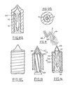
- Figure 12C is a side view of the projectile of Figures 12A and 12B
- Figure 13 shows another alternative embodiment.
- the external element 6 is in two parts, a cap 13C and a sleeve 16C secured to one another.
- the hammer mass 10A is directly integral with the front part 8A.
- the variant shown in FIG. 14 is slightly different by the shape of the hammer mass 10B which has, at the front, a flared part 43 facilitating its passage over the arrow-shaped tip 8B constituting the neutralizing part.
- the external part 6 consists of a first sleeve 16D and a shirt 16E.
- the bottom 10C of the hammer mass bears against the bottom of the external element 6 to avoid any separation at the time of the blow.
- the hammer mass is already pressed into the external element (assembly). This is, as already specified above, either an intentional situation realized during the manufacture of the cartridge, or, which is more general, the relative position of the different parts of the projectile after the start of the shot and its rotation.
- Figures 15 and 16 show two embodiments of a hammer mass.
- the hammer mass 10D has a conical housing 44 flared trumpet in its upper part. In the lower part, the hammer mass ends in a conical bead 45 intended to improve the seal.
- the embodiment of the hammer mass 10E of FIG. 16 is close to the hammer mass 10D of FIG. 15 except that this hammer mass comprises longitudinal incipient fractures 46, which facilitate the opening of the hammer mass at the time of impact.
- FIGS. 17A and 17B show the grooved external shape of a hammer mass 10. These figures reveal the helical grooves 12, as well as, in the case of the cut of FIG. 17B, the incipient fractures 46.
- Figures 18 and 19 show other embodiments of a hammer mass.
- the hammer mass 10E of FIG. 18 further comprises helical grooves 12 also of sawtooth section rings 47 constituting attachment means.
- FIG. 19 differs from that of FIG. 18 in that it comprises, in its lower part, a conical sealing bead 45.
- Figure 20 is an enlarged view of a variant of the front part 8 and especially of the shoulder 16B relative to the embodiment of Figure 7 so as to retain the hammer mass 10 at impact to avoid that, sliding on the rod 9, it does not open and deviate over the shoulder 16B.
- the hammer mass 10 communicates its energy to the neutralizing part 8 and remains integral with the latter.
- FIG. 21 shows, in detail, the assembly in a single piece formed by the neutralizing part 8 and the rod 9 terminated by a pointed end 18.
- FIG. 22 shows an alternative embodiment of the part shown in FIG. 21.
- the neutralizing part 8C is constituted by the constriction of a tube, itself flattened to form a zone 48 then the rod 9B which is formed a filling 49, for example made of lead or an active mass and a sheath 50 of the sleeve used to make the parts 8C and 48.
- FIG. 23 shows a particular embodiment of ribs 51 in the form of a knife situated upstream from the shoulder 16 of the neutralizing part 8 in order to open the hammer mass 10 more easily and more effectively.
- FIG. 24 shows explicitly in section an embodiment already mentioned above in the different variants.
- This variant is similar to those of FIGS. 4.5 both for the sleeve 19 and for the internal element 51 formed from a more tapered head or front part 8 ′, with a bicorne section and a rear rod 9.
- the mass -hammer 10 ′ threaded on the rear rod 9 is in the form of a bottomless sleeve, the inside of the sleeve 19 being closed by a plug 119 to seal against the propellants coming against the bottom, from the outside, so as not to remove the sleeve 19.
- the bottom plug 119 can be hooked to the sleeve 19 by a mechanical connection (connection by shape) but also by gluing (thermofusion), depending on the nature of the material of the sleeve 19 and the plug 119.
- the hammer mass 10 ′ has a shape adapted to that of the stopper so as to properly rest on it when firing and to avoid cutting or perforating it.
- this hammer mass 10 ′ advances on the rod 9 it rises on the cone of the front part 8 ′ and begins to flare while cooperating with the internal surface, before conical 1119 of the sleeve 19 so as to slightly swell the sleeve and improve sealing.
- the hammer mass is of relatively small size which, made possible thanks to the invention, allows powder saving and therefore also less nuisance (noise) or greater comfort for the hunter (less violent impact on his shoulder).
- the external surface of the sleeve 19 may have more or less accentuated peripheral grooves receiving, if necessary, a lubricant.
- the sleeve 19 is completely closed and its part su is open to manufacturing; the internal element 5 with the hammer mass 10 ′ are introduced by the tip and then the front of the sleeve 19 is closed, for example by heat sealing or gluing.
- the sleeve 19 can be made in two abutted or nested parts and secured to one another.
Landscapes
- Engineering & Computer Science (AREA)
- General Engineering & Computer Science (AREA)
- Percussive Tools And Related Accessories (AREA)
- Aiming, Guidance, Guns With A Light Source, Armor, Camouflage, And Targets (AREA)
- Curing Cements, Concrete, And Artificial Stone (AREA)
- Telescopes (AREA)
- Portable Nailing Machines And Staplers (AREA)
- General Details Of Gearings (AREA)
Priority Applications (1)
| Application Number | Priority Date | Filing Date | Title |
|---|---|---|---|
| AT89400554T ATE89072T1 (de) | 1988-02-29 | 1989-02-28 | Munition fuer feuerwaffen, insbesondere flintenlaufmunition. |
Applications Claiming Priority (3)
| Application Number | Priority Date | Filing Date | Title |
|---|---|---|---|
| FR8802475 | 1988-02-29 | ||
| FR8802475A FR2627854B1 (fr) | 1988-02-29 | 1988-02-29 | Munition pour armes a feu, notamment munition de chasse |
| CA000609605A CA1333544C (fr) | 1988-02-29 | 1989-08-28 | Munition pour armes a feu, notamment munition de chasse |
Publications (2)
| Publication Number | Publication Date |
|---|---|
| EP0333542A1 true EP0333542A1 (de) | 1989-09-20 |
| EP0333542B1 EP0333542B1 (de) | 1993-05-05 |
Family
ID=25672985
Family Applications (1)
| Application Number | Title | Priority Date | Filing Date |
|---|---|---|---|
| EP89400554A Expired - Lifetime EP0333542B1 (de) | 1988-02-29 | 1989-02-28 | Munition für Feuerwaffen, insbesondere Flintenlaufmunition |
Country Status (8)
| Country | Link |
|---|---|
| US (1) | US4977834A (de) |
| EP (1) | EP0333542B1 (de) |
| AT (1) | ATE89072T1 (de) |
| AU (1) | AU608998B1 (de) |
| CA (1) | CA1333544C (de) |
| DE (1) | DE68906298T2 (de) |
| ES (1) | ES2042017T3 (de) |
| FR (1) | FR2627854B1 (de) |
Cited By (5)
| Publication number | Priority date | Publication date | Assignee | Title |
|---|---|---|---|---|
| FR2724450A1 (fr) * | 1994-09-13 | 1996-03-15 | Sauvestre Jean Claude | Balle de chasse a double penetration et a portee reduite |
| WO1996008708A1 (en) * | 1994-09-13 | 1996-03-21 | Mobil Oil Corporation | Method for monitoring grease consistency |
| FR2726357A1 (fr) * | 1994-10-26 | 1996-05-03 | Sauvestre Jean Claude | Balle de chasse a fleche telescopee, comportant un sous-projectile associe a un lanceur |
| FR2880680A1 (fr) * | 2005-01-10 | 2006-07-14 | Jean Pierre Denis | Munition d'entrainement et d'intervention |
| WO2009056082A1 (de) * | 2007-11-02 | 2009-05-07 | Jallcom Holdings Ltd. | Munition zum verschliessen aus einem glatten rohr |
Families Citing this family (25)
| Publication number | Priority date | Publication date | Assignee | Title |
|---|---|---|---|---|
| CA1333543C (fr) * | 1987-10-05 | 1994-12-20 | Jean-Pierre Denis | Projectile destine a etre tire par une arme a feu |
| US5149913A (en) * | 1990-09-05 | 1992-09-22 | Arakaki Steven Y | Forced expanding bullet |
| FR2673278B1 (fr) * | 1991-02-26 | 1993-12-31 | Giat Industries | Projectile sous-calibre perforant fragmentable. |
| US5185495A (en) * | 1992-04-13 | 1993-02-09 | Petrovich Robert M | Projective with improved flowering |
| DE19754330C1 (de) * | 1997-11-22 | 1999-04-08 | Wilhelm Brenneke Gmbh & Co Kg | Unterkalibriges Flintenlaufgeschoß, insbesondere für Flinten mit teilweise oder ganz gezogenem Lauf |
| FR2795170B1 (fr) * | 1999-06-18 | 2002-06-28 | Jean Claude Sauvestre | Balle a fleche interne portee |
| JP3313097B2 (ja) * | 1999-11-10 | 2002-08-12 | 永山電子工業株式会社 | 金属製締結部材および砲弾用外装部材 |
| FR2817337B1 (fr) * | 2000-11-24 | 2004-06-18 | Jean Pierre Denis | Munition comportant un projectile forme d'une fleche, d'une masse-marteau et d'une enveloppe recevant cet ensemble |
| US6679178B2 (en) * | 2000-12-21 | 2004-01-20 | Gueorgui M. Mihaylov | Smooth bore barrel system with self spinning ammunition |
| DE50211965D1 (de) * | 2001-04-19 | 2008-05-08 | Ruag Ammotec Gmbh | Geschoss für infanteriemunition |
| US7444942B2 (en) * | 2005-12-23 | 2008-11-04 | Accura Bullets, Llc | Saboted projectile with external ridges and/or internal locking edge for muzzleloading firearms |
| US20110048272A1 (en) * | 2001-09-27 | 2011-03-03 | Hall Daniel W | Gas check with system for improved loading and retention in bore of muzzleloading firearms |
| US7827915B1 (en) * | 2001-09-27 | 2010-11-09 | Accura Bullets | Gas check with system for improved loading and retention in bore of muzzleloading firearms |
| US7096791B2 (en) * | 2002-07-12 | 2006-08-29 | Arthur Vanmoor | Projectile with improved dynamic shape |
| DE10244571C1 (de) * | 2002-09-25 | 2003-12-04 | Wilhelm Brenneke Gmbh & Co Kg | Flintenlaufgeschoss |
| US7681504B2 (en) * | 2003-08-26 | 2010-03-23 | Bae Systems Information And Electronic Systems Integration Inc. | Method and apparatus for displacing material and projectile thereof |
| UA91671C2 (ru) * | 2003-10-11 | 2010-08-25 | Руаг Аммотек Гмбх | Снаряд для ружейного ствола с промежуточным средством и патрон |
| FR2863046B1 (fr) * | 2003-11-25 | 2006-08-11 | Jean Pierre Denis | Munition |
| FR2867267B1 (fr) * | 2004-03-08 | 2006-05-26 | Jean Claude Sauvestre | Balle de chasse a bague d'expansion |
| KR100843573B1 (ko) * | 2008-03-13 | 2008-07-03 | (주)한국원자력 엔지니어링 | 탄약 |
| US11231257B2 (en) * | 2010-11-10 | 2022-01-25 | True Velocity Ip Holdings, Llc | Method of making a metal injection molded ammunition cartridge |
| US9372058B2 (en) * | 2011-12-28 | 2016-06-21 | Randy R. Fritz | Hollow bullet with internal structure |
| WO2016007212A2 (en) * | 2014-04-10 | 2016-01-14 | Mahnke Joshua | Projectile with enhanced ballistics |
| USD1055200S1 (en) | 2014-04-30 | 2024-12-24 | G9 Holdings, Llc | Projectile |
| US11867487B1 (en) | 2021-03-03 | 2024-01-09 | Wach Llc | System and method for aeronautical stabilization |
Citations (4)
| Publication number | Priority date | Publication date | Assignee | Title |
|---|---|---|---|---|
| US2493938A (en) * | 1946-12-09 | 1950-01-10 | Albree George Norman | Ammunition |
| FR1457971A (fr) * | 1964-12-12 | 1966-11-04 | Dynamit Nobel Ag | Projectile chemisé pour cartouches de chasse |
| DE1578119A1 (de) * | 1967-06-06 | 1970-08-27 | Dynamit Nobel Ag | Flintenlaufgeschoss |
| DE2929628A1 (de) * | 1979-07-21 | 1981-02-12 | Brenneke Wilhelm Kg | Patrone mit flintenlaufgeschoss |
Family Cites Families (12)
| Publication number | Priority date | Publication date | Assignee | Title |
|---|---|---|---|---|
| US904255A (en) * | 1907-12-07 | 1908-11-17 | Emil Gathmann | Projectile. |
| US3318244A (en) * | 1965-07-01 | 1967-05-09 | Charles E Rostocil | Cartridge |
| US3398682A (en) * | 1966-09-14 | 1968-08-27 | Michael F. Abela | Spinning projectile |
| FR2300319A1 (fr) * | 1975-02-07 | 1976-09-03 | Cleard Gilbert | Projectile pour arme a feu |
| FR2335818A1 (fr) * | 1975-12-19 | 1977-07-15 | Le Neillon Richard | Projectile pour armes de chasse |
| IT1196905B (it) * | 1979-10-26 | 1988-11-25 | Snia Viscosa | Proiettili per fucili da caccia a canna liscia |
| US4413564A (en) * | 1981-05-01 | 1983-11-08 | Brown Worthy H | Slug for a shotgun shell |
| FR2513369A1 (fr) * | 1981-09-24 | 1983-03-25 | Robert Antoine | Projectiles pour armes de poing et d'epaule a canon lisse ou raye a tres hautes vitesses initiales, conformes aux conventions de la haye et produisant les memes effets neutralisants que les projectiles a pointe creuse ou explosive. revendication : deux dispositifs, une utilisation. |
| DE3241149C2 (de) * | 1982-11-08 | 1984-12-20 | Wilhelm Brenneke Kg Fabrikation Von Jagdgeschossen, 3012 Langenhagen | Flintenlaufgeschoß |
| PT77697B (fr) * | 1982-11-24 | 1986-02-12 | Ladriere Serge | Projectile perfectionne destine a etre decharge par des armes a feu |
| AU5626286A (en) * | 1985-03-27 | 1986-10-23 | Scientific Cartridge Developments Ltd. | Shotgun cartridge |
| AU5359086A (en) * | 1986-01-23 | 1987-08-14 | Johnson, P.I. | Shotgun slug cartridge |
-
1988
- 1988-02-29 FR FR8802475A patent/FR2627854B1/fr not_active Expired - Lifetime
-
1989
- 1989-02-28 AT AT89400554T patent/ATE89072T1/de not_active IP Right Cessation
- 1989-02-28 DE DE89400554T patent/DE68906298T2/de not_active Expired - Fee Related
- 1989-02-28 ES ES198989400554T patent/ES2042017T3/es not_active Expired - Lifetime
- 1989-02-28 EP EP89400554A patent/EP0333542B1/de not_active Expired - Lifetime
- 1989-08-28 CA CA000609605A patent/CA1333544C/fr not_active Expired - Fee Related
- 1989-08-28 US US07/399,193 patent/US4977834A/en not_active Expired - Lifetime
- 1989-08-29 AU AU40874/89A patent/AU608998B1/en not_active Ceased
Patent Citations (4)
| Publication number | Priority date | Publication date | Assignee | Title |
|---|---|---|---|---|
| US2493938A (en) * | 1946-12-09 | 1950-01-10 | Albree George Norman | Ammunition |
| FR1457971A (fr) * | 1964-12-12 | 1966-11-04 | Dynamit Nobel Ag | Projectile chemisé pour cartouches de chasse |
| DE1578119A1 (de) * | 1967-06-06 | 1970-08-27 | Dynamit Nobel Ag | Flintenlaufgeschoss |
| DE2929628A1 (de) * | 1979-07-21 | 1981-02-12 | Brenneke Wilhelm Kg | Patrone mit flintenlaufgeschoss |
Cited By (9)
| Publication number | Priority date | Publication date | Assignee | Title |
|---|---|---|---|---|
| FR2724450A1 (fr) * | 1994-09-13 | 1996-03-15 | Sauvestre Jean Claude | Balle de chasse a double penetration et a portee reduite |
| WO1996008708A1 (en) * | 1994-09-13 | 1996-03-21 | Mobil Oil Corporation | Method for monitoring grease consistency |
| WO1996008689A1 (fr) * | 1994-09-13 | 1996-03-21 | Sauvestre Jean Claude | Balle de chasse a double penetration et a portee reduite |
| US5723810A (en) * | 1994-09-13 | 1998-03-03 | Sauvestre; Jean-Claude | Double-penetration reduced-range hunting bullet |
| FR2726357A1 (fr) * | 1994-10-26 | 1996-05-03 | Sauvestre Jean Claude | Balle de chasse a fleche telescopee, comportant un sous-projectile associe a un lanceur |
| WO1996013697A1 (fr) * | 1994-10-26 | 1996-05-09 | Sauvestre Jean Claude | Balle de chasse a fleche telescopee, comportant un sous-projectile associe a un lanceur |
| US5804759A (en) * | 1994-10-26 | 1998-09-08 | Sauvestre; Jean-Claude | Hunting bullet having a telescoping flechette and comprising a sub-projectile connected to a launcher |
| FR2880680A1 (fr) * | 2005-01-10 | 2006-07-14 | Jean Pierre Denis | Munition d'entrainement et d'intervention |
| WO2009056082A1 (de) * | 2007-11-02 | 2009-05-07 | Jallcom Holdings Ltd. | Munition zum verschliessen aus einem glatten rohr |
Also Published As
| Publication number | Publication date |
|---|---|
| ES2042017T3 (es) | 1993-12-01 |
| ATE89072T1 (de) | 1993-05-15 |
| AU608998B1 (en) | 1991-04-18 |
| FR2627854A1 (fr) | 1989-09-01 |
| DE68906298D1 (de) | 1993-06-09 |
| DE68906298T2 (de) | 1993-12-02 |
| CA1333544C (fr) | 1994-12-20 |
| EP0333542B1 (de) | 1993-05-05 |
| US4977834A (en) | 1990-12-18 |
| FR2627854B1 (fr) | 1990-08-10 |
Similar Documents
| Publication | Publication Date | Title |
|---|---|---|
| EP0333542B1 (de) | Munition für Feuerwaffen, insbesondere Flintenlaufmunition | |
| CA1333543C (fr) | Projectile destine a etre tire par une arme a feu | |
| EP1188032B1 (de) | Expansionsgeschoss | |
| CA2558031C (fr) | Balle de chasse a bague d'expansion | |
| EP2691731B1 (de) | Weniger todbringendes geschoss für eine waffe | |
| EP2297545B1 (de) | Nicht tödliche munition | |
| FR2529319A1 (fr) | Munition comportant une charge propulsive et un projectile stabilise par ailettes | |
| EP0106263B1 (de) | Panzerbrechendes Sprenggeschoss versehen mit einer Treibladungshülse | |
| EP0572643B1 (de) | Kugelfang fuer gewehrgranate mit kugelsplitterfangeinrichtung | |
| EP0737298B1 (de) | Flintenlaufgeschoss mit teleskopartigem pfeil mit einem an einem launcher teilnehmenden subgeschoss | |
| EP0728293B1 (de) | Flintenlaufgeschoss mit doppeleindringung und reduzierter schussweite | |
| WO1991002211A1 (fr) | Perfectionnements apportes aux munitions destinees a etre tirees par une arme a canon lisse | |
| EP0310723A1 (de) | Kugel für ein Gewehr | |
| FR2719373A1 (fr) | Dispositif de propulsion à portées variables pour grenade anti-émeutes. | |
| CA1337544C (fr) | Projectile destine a etre tire par une arme a feu | |
| EP0382657A1 (de) | Patrone für Gewehre oder andere Feuerwaffen | |
| FR2538892A1 (fr) | Projectile d'entrainement au tir de mortier et sa fusee | |
| EP1023573B1 (de) | Treibkäfig mit verbesserter gasabdichtung für submunitionskörper | |
| FR2950688A1 (fr) | Projectile pour arme a letalite reduite | |
| BE708180A (de) | ||
| FR2732456A1 (fr) | Amorces de rupture de ceinture pour projectile fleche |
Legal Events
| Date | Code | Title | Description |
|---|---|---|---|
| PUAI | Public reference made under article 153(3) epc to a published international application that has entered the european phase |
Free format text: ORIGINAL CODE: 0009012 |
|
| AK | Designated contracting states |
Kind code of ref document: A1 Designated state(s): AT BE CH DE ES GB GR IT LI LU NL SE |
|
| 17P | Request for examination filed |
Effective date: 19900308 |
|
| 17Q | First examination report despatched |
Effective date: 19910808 |
|
| GRAA | (expected) grant |
Free format text: ORIGINAL CODE: 0009210 |
|
| AK | Designated contracting states |
Kind code of ref document: B1 Designated state(s): AT BE CH DE ES GB GR IT LI LU NL SE |
|
| PG25 | Lapsed in a contracting state [announced via postgrant information from national office to epo] |
Ref country code: SE Effective date: 19930505 Ref country code: NL Effective date: 19930505 Ref country code: AT Effective date: 19930505 |
|
| REF | Corresponds to: |
Ref document number: 89072 Country of ref document: AT Date of ref document: 19930515 Kind code of ref document: T |
|
| REF | Corresponds to: |
Ref document number: 68906298 Country of ref document: DE Date of ref document: 19930609 |
|
| ITF | It: translation for a ep patent filed | ||
| GBT | Gb: translation of ep patent filed (gb section 77(6)(a)/1977) |
Effective date: 19930811 |
|
| NLV1 | Nl: lapsed or annulled due to failure to fulfill the requirements of art. 29p and 29m of the patents act | ||
| REG | Reference to a national code |
Ref country code: GR Ref legal event code: FG4A Free format text: 3008687 |
|
| REG | Reference to a national code |
Ref country code: ES Ref legal event code: FG2A Ref document number: 2042017 Country of ref document: ES Kind code of ref document: T3 |
|
| PG25 | Lapsed in a contracting state [announced via postgrant information from national office to epo] |
Ref country code: LU Free format text: LAPSE BECAUSE OF NON-PAYMENT OF DUE FEES Effective date: 19940228 Ref country code: LI Effective date: 19940228 Ref country code: CH Effective date: 19940228 |
|
| PLBE | No opposition filed within time limit |
Free format text: ORIGINAL CODE: 0009261 |
|
| STAA | Information on the status of an ep patent application or granted ep patent |
Free format text: STATUS: NO OPPOSITION FILED WITHIN TIME LIMIT |
|
| 26N | No opposition filed | ||
| REG | Reference to a national code |
Ref country code: CH Ref legal event code: PL |
|
| REG | Reference to a national code |
Ref country code: CH Ref legal event code: AUV Free format text: LE BREVET CI-DESSUS EST TOMBE EN DECHEANCE, FAUTE DE PAIEMENT, DE LA 6E ANNUITE. |
|
| REG | Reference to a national code |
Ref country code: GB Ref legal event code: IF02 |
|
| PGFP | Annual fee paid to national office [announced via postgrant information from national office to epo] |
Ref country code: GR Payment date: 20040227 Year of fee payment: 16 |
|
| PG25 | Lapsed in a contracting state [announced via postgrant information from national office to epo] |
Ref country code: GR Free format text: LAPSE BECAUSE OF NON-PAYMENT OF DUE FEES Effective date: 20050905 |
|
| PGFP | Annual fee paid to national office [announced via postgrant information from national office to epo] |
Ref country code: GB Payment date: 20070227 Year of fee payment: 19 |
|
| PGFP | Annual fee paid to national office [announced via postgrant information from national office to epo] |
Ref country code: ES Payment date: 20070228 Year of fee payment: 19 |
|
| PGFP | Annual fee paid to national office [announced via postgrant information from national office to epo] |
Ref country code: BE Payment date: 20070305 Year of fee payment: 19 |
|
| PGFP | Annual fee paid to national office [announced via postgrant information from national office to epo] |
Ref country code: DE Payment date: 20070327 Year of fee payment: 19 |
|
| PGFP | Annual fee paid to national office [announced via postgrant information from national office to epo] |
Ref country code: IT Payment date: 20070517 Year of fee payment: 19 |
|
| BERE | Be: lapsed |
Owner name: *DENIS JEAN-PIERRE Effective date: 20080228 |
|
| GBPC | Gb: european patent ceased through non-payment of renewal fee |
Effective date: 20080228 |
|
| PG25 | Lapsed in a contracting state [announced via postgrant information from national office to epo] |
Ref country code: DE Free format text: LAPSE BECAUSE OF NON-PAYMENT OF DUE FEES Effective date: 20080902 |
|
| PG25 | Lapsed in a contracting state [announced via postgrant information from national office to epo] |
Ref country code: BE Free format text: LAPSE BECAUSE OF NON-PAYMENT OF DUE FEES Effective date: 20080228 |
|
| REG | Reference to a national code |
Ref country code: ES Ref legal event code: FD2A Effective date: 20080229 |
|
| PG25 | Lapsed in a contracting state [announced via postgrant information from national office to epo] |
Ref country code: GB Free format text: LAPSE BECAUSE OF NON-PAYMENT OF DUE FEES Effective date: 20080228 |
|
| PG25 | Lapsed in a contracting state [announced via postgrant information from national office to epo] |
Ref country code: ES Free format text: LAPSE BECAUSE OF NON-PAYMENT OF DUE FEES Effective date: 20080229 |
|
| PG25 | Lapsed in a contracting state [announced via postgrant information from national office to epo] |
Ref country code: IT Free format text: LAPSE BECAUSE OF NON-PAYMENT OF DUE FEES Effective date: 20080228 |