EP0333552B1 - Sonde, Vorrichtung zur Bilderstellung mit dieser Sonde und Verfahren zur Benutzung dieser Vorrichtung - Google Patents
Sonde, Vorrichtung zur Bilderstellung mit dieser Sonde und Verfahren zur Benutzung dieser Vorrichtung Download PDFInfo
- Publication number
- EP0333552B1 EP0333552B1 EP89400610A EP89400610A EP0333552B1 EP 0333552 B1 EP0333552 B1 EP 0333552B1 EP 89400610 A EP89400610 A EP 89400610A EP 89400610 A EP89400610 A EP 89400610A EP 0333552 B1 EP0333552 B1 EP 0333552B1
- Authority
- EP
- European Patent Office
- Prior art keywords
- transductors
- firing
- image
- electro
- transducers
- Prior art date
- Legal status (The legal status is an assumption and is not a legal conclusion. Google has not performed a legal analysis and makes no representation as to the accuracy of the status listed.)
- Expired - Lifetime
Links
- 230000015572 biosynthetic process Effects 0.000 title description 6
- 238000000034 method Methods 0.000 title description 4
- 230000001939 inductive effect Effects 0.000 claims description 2
- 238000010304 firing Methods 0.000 claims 6
- 239000000523 sample Substances 0.000 description 26
- 238000010586 diagram Methods 0.000 description 9
- 238000002604 ultrasonography Methods 0.000 description 6
- 230000001934 delay Effects 0.000 description 5
- 238000003384 imaging method Methods 0.000 description 5
- 230000005540 biological transmission Effects 0.000 description 4
- 238000002059 diagnostic imaging Methods 0.000 description 4
- 230000015654 memory Effects 0.000 description 3
- 210000000056 organ Anatomy 0.000 description 3
- 238000003745 diagnosis Methods 0.000 description 2
- 238000013459 approach Methods 0.000 description 1
- 230000000747 cardiac effect Effects 0.000 description 1
- 230000008878 coupling Effects 0.000 description 1
- 238000010168 coupling process Methods 0.000 description 1
- 238000005859 coupling reaction Methods 0.000 description 1
- 230000005021 gait Effects 0.000 description 1
- 239000007788 liquid Substances 0.000 description 1
- 238000009659 non-destructive testing Methods 0.000 description 1
- 238000009738 saturating Methods 0.000 description 1
- 230000003936 working memory Effects 0.000 description 1
Images


Classifications
-
- G—PHYSICS
- G10—MUSICAL INSTRUMENTS; ACOUSTICS
- G10K—SOUND-PRODUCING DEVICES; METHODS OR DEVICES FOR PROTECTING AGAINST, OR FOR DAMPING, NOISE OR OTHER ACOUSTIC WAVES IN GENERAL; ACOUSTICS NOT OTHERWISE PROVIDED FOR
- G10K11/00—Methods or devices for transmitting, conducting or directing sound in general; Methods or devices for protecting against, or for damping, noise or other acoustic waves in general
- G10K11/18—Methods or devices for transmitting, conducting or directing sound
- G10K11/26—Sound-focusing or directing, e.g. scanning
- G10K11/34—Sound-focusing or directing, e.g. scanning using electrical steering of transducer arrays, e.g. beam steering
- G10K11/341—Circuits therefor
- G10K11/346—Circuits therefor using phase variation
-
- G—PHYSICS
- G01—MEASURING; TESTING
- G01N—INVESTIGATING OR ANALYSING MATERIALS BY DETERMINING THEIR CHEMICAL OR PHYSICAL PROPERTIES
- G01N29/00—Investigating or analysing materials by the use of ultrasonic, sonic or infrasonic waves; Visualisation of the interior of objects by transmitting ultrasonic or sonic waves through the object
- G01N29/22—Details, e.g. general constructional or apparatus details
- G01N29/26—Arrangements for orientation or scanning by relative movement of the head and the sensor
- G01N29/262—Arrangements for orientation or scanning by relative movement of the head and the sensor by electronic orientation or focusing, e.g. with phased arrays
-
- G—PHYSICS
- G01—MEASURING; TESTING
- G01N—INVESTIGATING OR ANALYSING MATERIALS BY DETERMINING THEIR CHEMICAL OR PHYSICAL PROPERTIES
- G01N29/00—Investigating or analysing materials by the use of ultrasonic, sonic or infrasonic waves; Visualisation of the interior of objects by transmitting ultrasonic or sonic waves through the object
- G01N29/34—Generating the ultrasonic, sonic or infrasonic waves, e.g. electronic circuits specially adapted therefor
- G01N29/341—Generating the ultrasonic, sonic or infrasonic waves, e.g. electronic circuits specially adapted therefor with time characteristics
-
- G—PHYSICS
- G01—MEASURING; TESTING
- G01N—INVESTIGATING OR ANALYSING MATERIALS BY DETERMINING THEIR CHEMICAL OR PHYSICAL PROPERTIES
- G01N29/00—Investigating or analysing materials by the use of ultrasonic, sonic or infrasonic waves; Visualisation of the interior of objects by transmitting ultrasonic or sonic waves through the object
- G01N29/36—Detecting the response signal, e.g. electronic circuits specially adapted therefor
- G01N29/38—Detecting the response signal, e.g. electronic circuits specially adapted therefor by time filtering, e.g. using time gates
-
- G—PHYSICS
- G01—MEASURING; TESTING
- G01N—INVESTIGATING OR ANALYSING MATERIALS BY DETERMINING THEIR CHEMICAL OR PHYSICAL PROPERTIES
- G01N2291/00—Indexing codes associated with group G01N29/00
- G01N2291/10—Number of transducers
- G01N2291/106—Number of transducers one or more transducer arrays
-
- G—PHYSICS
- G01—MEASURING; TESTING
- G01N—INVESTIGATING OR ANALYSING MATERIALS BY DETERMINING THEIR CHEMICAL OR PHYSICAL PROPERTIES
- G01N2291/00—Indexing codes associated with group G01N29/00
- G01N2291/26—Scanned objects
- G01N2291/263—Surfaces
- G01N2291/2634—Surfaces cylindrical from outside
Definitions
- the main object of the invention is an ultrasound ultrasound probe, an imaging device using such a probe and a method using such a device.
- ultrasound ultrasound probes are known.
- sector scanning probes that is to say comprising either an oscillating mobile assembly or several electro-acoustic transducers mounted on a wheel and switched in their passage in front of an emission window.
- the qualities of these probes are their speed of acquisition and their simplicity of principle which results in relatively simple and inexpensive signal processing means.
- the coupling surface of the acoustic waves is relatively small, which makes it possible to place the probe between two ribs of the patient for cardiac observations.
- the lifespan of these probes is limited.
- probes comprising a plurality of electro-acoustic transducers.
- linear scanning device comprising a linear strip comprising, for example 64 elementary electro-acoustic transducers.
- the scanning is carried out by moving for each shot, that is to say emission of ultrasonic waves, the group of active transducers.
- This type of linear strip has a low resolution due to the low number of transducers used simultaneously.
- An important originality of the present invention lies in the fact of using all the transducers capable of insonifying a direction to form an image corresponding to this region. Focusing is achieved by electronic scanning using delay elements. The delays to be achieved are less significant than in the case of a linear bar due to the very geometry of the curved bar. In addition, the scanning angle is much higher, passing, for example, from 90 ° to 150 °.
- the invention relates to a device as described in the claims.
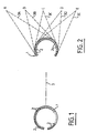
- FIGS. 1 to 3 the same references have been used to designate the same elements.
- an ultrasound probe 1 comprising a plurality of electro-acoustic transducers 2, advantageously regularly distributed.
- the probe has an arc shape. It is understood that other forms, such as for example a hyperbola, an elliptical arc or a parabola do not depart from the scope of the present invention.
- the probe 1 has an axis of symmetry 3. When producing images it will be advantageous to place the point of interest on the axis 3.
- the probe 1 is capable of producing images in a sector centered on the axis 3
- the sector scanning will be obtained by applying variable delays to the transducers 2.
- the probe 1 does not include transducers opposite the axis 3. In fact, such transducers can never participate in a image of a sector centered on axis 3.
- the electro-acoustic transducers are advantageously piezoelectric transducers.
- the probe 1 comprises a plurality of electro-acoustic transducers 2 arranged regularly on a circle in the example illustrated in FIG. 2.
- a point is insonified by focusing the ultrasonic energy by an electronic scan, that is to say that delays are applied to the signals generated by the transducers 2 so as to compensate for differences in gait.
- the electro-acoustic transducers 2 have their own directivity, and on the other hand, the geometry of the probe 1 does not allow all the electro-acoustic transducers 2 to illuminate all the points of the object to observe.
- the electro-acoustic transducers 2 can be used to insonate a point to obtain an image of it. This principle is valid both for a two-dimensional electronic scan for which each emission will correspond to a line of the image as for a three-dimensional electronic scanning for which each emission will correspond to a point of the image.
- sectors 3a, 3b, 3c, 3d and 3e have illustrated by transducers capable of insonating the point or the lines passing through the points respectively A, B, C, D and E.
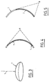
- a spherical cap capable of serving as a support for a probe 1.
- the distribution of the electro-acoustic transducers 2 not shown in Figure 3, on a spherical cap allows focusing three-dimensional acoustic energy beam. It is possible to direct the beams, either by carrying out a three-dimensional electronic scanning, or by grouping the transducers into rings and by associating with these rings addressing means corresponding to the various regions of the space to be exploited. This latter method has been described in Patent No. 83,016,550 filed on October 18, 1983 by the Company CGR ULTRASONIC.
- zone 7 of the electro-acoustic transducers not illustrated in the figure, likely to insonify point B is less important than in the case of figure 4.
- the area 7 is reduced, and with it image resolution.
- a reduced resolution is obtained corresponding to the resolution of the systems of the prior art.
- an image is obtained whose center has a very high resolution and having a large angle of view.
- the edges are mainly used to locate the organs relative to each other, so to find their bearings do not require very high resolution.
- the organ to be examined is placed in the center of the image, requiring maximum resolution. Frequently the doctor using the device according to the present invention will not even notice the drop in resolution on the edge.
- the probe 1 for example to form an almost complete circle, as illustrated in FIG. 1, without departing from the scope of the present invention.
- the resolution will be the same at the center and at the edge of the image at the cost of an increase in the number of transducers necessary for the implementation of a probe.
- this increases the angle of view.
- FIG. 6 we can see a first embodiment of an ultrasound device according to the present invention.
- the device comprises a plurality of electro-acoustic transducers 2.
- the electro-acoustic transducers 2 are shown aligned. It is understood that any desired geometry, such as for example a convex radiating surface can be adopted to produce the device according to the present invention.
- the electro-acoustic transducers 2 receive electrical energy through a multiplexing device 60 and a variable delay device 4.
- the electro-acoustic transducers 2 are connected through delay devices 4 and multiplexers 60 and a receiver 8.
- the receiver 8 is connected to a signal processing device 9.
- the signal processing device 9 is connected to an operating device 10 such as for example a display device comprising, for example, a cathode ray tube, an image memory, an image storage device or an image processing device.
- a control device 5 is connected to the delay device 4 by links 52 to the multiplexer 60 by a bus 53 to the transmitter 6 by a control 51.
- the control device 5 determines for each line of the image, the electro-acoustic transducer 2 to be implemented, controls the adjustment of the multiplexer 60 to allow this implementation and the adjustment of a delay device 4 to obtain the desired focus. Only the transducers having to participate in a transmission are supplied by the transmitter 6 via the multiplexer 60.
- At least the transducers 2 which participated in the transmission are connected via the multiplexer 60 to the receiver 8.
- the control device 5 ensures via the line 51 the synchronization between the transmission and the reception. Indeed, it is important that the transmitter 6 does not transmit during reception so that the signal from the transmitter 6 does not disturb the operation of the receiver 8. Indeed, if we do not take precautions the signal of the the transmitter 6 risks saturating the receiver 8.
- the multiplexer 60 comprises for example a cascade assembly of analog multiplexers such as for example the analog multiplexer sold under the reference DG 507 by the company Siliconix.
- the delay elements 4 are for example delay lines, the delay is selected by switching a signal data path in the delay lines.
- the signal processing device 9 comprises for example signal processors, filters, multipliers, adders and / or fast Fourier transform calculators.
- the control device 5 ensures the proper functioning of the device according to the present invention. It performs addressing, synchronization of transmissions and receptions.
- Various types of control devices 5 can be used.
- a control device 5 comprising a sequencer comprising counters which address a memory in which the addresses to be implemented are stored.
- the control device 5 comprises at least one arithmetic and logic unit, for example contained in a microprocessor, a read-only memory containing the program and an empty working memory.
- control unit 5 receives control commands from the user by a control bus 55.
- the transmitter 6 and the receiver 8 are connected to the electro-acoustic transducer 2 via a delay device 13 of the multiplexer 60 to a switching device 14 connected in series .
- the control unit 5 is connected by a bus 52 to the delay device 13 by a bus 53 to the multiplexer 60 and by a bus 12 to the switching device 14.
- the control unit 5 is connected to the transmitter 6.
- the delay device 13 comprises delay lines capable of being connected in series and / or in parallel. Thus, the delay device 13 makes it possible to simultaneously obtain the various delay values necessary for the operation of the probe.
- the switching device 14 associated with the multiplexer 60 makes it possible to connect the right delay elements to the right electro-acoustic transducer 2.
- the device as illustrated in FIG. 7 has the advantage of reducing the number of delay lines necessary for the proper functioning of the device.
- each electro-acoustic transducer 2 is associated with a transmitter 6 and a delay element 130.
- the control device 5 is connected by control lines 51 to the transmitters 6 and by lines of command 52 to delay elements 130.
- the electro-acoustic transducers 2 are connected via the delay elements 130 to a receiver 8.
- the receiver 8 is connected to a signal processing device 9.
- the signal processing device 9 is connected to a operation 10 such as for example a display device.
- the invention applies to imaging using acoustic waves, such as for example ultrasonic waves.
- the invention applies in particular to non-destructive testing for obtaining images inside liquids, such as for example underwater images.
- the invention applies mainly to ultrasonic medical imaging.
Landscapes
- Physics & Mathematics (AREA)
- Biochemistry (AREA)
- General Physics & Mathematics (AREA)
- Pathology (AREA)
- Health & Medical Sciences (AREA)
- Life Sciences & Earth Sciences (AREA)
- Chemical & Material Sciences (AREA)
- Immunology (AREA)
- Analytical Chemistry (AREA)
- General Health & Medical Sciences (AREA)
- Engineering & Computer Science (AREA)
- Acoustics & Sound (AREA)
- Multimedia (AREA)
- Ultra Sonic Daignosis Equipment (AREA)
- Investigating Or Analyzing Materials By The Use Of Ultrasonic Waves (AREA)
- Transducers For Ultrasonic Waves (AREA)
- Measurement Of Velocity Or Position Using Acoustic Or Ultrasonic Waves (AREA)
Claims (4)
- Echographieeinrichtung, mit mehreren piezoelektrischen Ultraschallwandlern (2), die sich auf einer konvexen Fläche befinden, mit Verzögerungselementen (4), die dazu geeignet sind, den den piezoelektrischen Ultraschallwandlern (2) zugehörigen Signalen eine Verzögerung zu verleihen, und Mitteln (60) zum Umschalten von einer Senderichtung zu einer benachbarten Senderichtung, mit denen in Abhängigkeit von einer Senderichtung eine optimierte Anzahl von Ultraschallwandlern (2) aktiviert werden kann, derart, daß diese Senderichtung am besten beschallt wird, wobei die verwendeten Ultraschallwandler stets eine für diese zwei Richtungen gemeinsam genutzte Ultraschallwandler-Gruppe umfassen, dadurch gekennzeichnet, daß diese optimierte Anzahl bei einer zentralen Senderichtung größer als bei seitlichen Senderichtungen ist.
- Echographieeinrichtung gemäß Anspruch 1, dadurch gekennzeichnet, daß sich die piezoelektrischen Ultraschallwandler (2) auf einem konvexen Kreisbogen befinden.
- Einrichtung gemäß Anspruch 1, dadurch gekennzeichnet, daß sich die piezoelektrischen Ultraschallwandler (2) auf einem Teil einer sphärischen Fläche befinden.
- Einrichtung gemäß Anspruch 3, dadurch gekennzeichnet, daß sie eine automatische Steuereinrichtung (5) umfaßt, die dazu geeignet ist, diejenigen piezoelektrischen Ultraschallwandler (2) zu bestimmen, die in Betrieb gesetzt werden müssen, um für jeden Azimutwinkel eine Schallwelle zu senden und/oder zu empfangen, die auf die aktiven Ultraschallwandler (2) anzuwendenden Verzögerungswerte zu bestimmen und/oder die Sende-/Empfangssynchronisation auszuführen.
Applications Claiming Priority (2)
| Application Number | Priority Date | Filing Date | Title |
|---|---|---|---|
| FR8803185A FR2628539B1 (fr) | 1988-03-11 | 1988-03-11 | Sonde, dispositif d'imagerie utilisant une telle sonde et procede mettant en oeuvre un tel dispositif |
| FR8803185 | 1988-03-11 |
Publications (2)
| Publication Number | Publication Date |
|---|---|
| EP0333552A1 EP0333552A1 (de) | 1989-09-20 |
| EP0333552B1 true EP0333552B1 (de) | 1993-04-28 |
Family
ID=9364180
Family Applications (1)
| Application Number | Title | Priority Date | Filing Date |
|---|---|---|---|
| EP89400610A Expired - Lifetime EP0333552B1 (de) | 1988-03-11 | 1989-03-03 | Sonde, Vorrichtung zur Bilderstellung mit dieser Sonde und Verfahren zur Benutzung dieser Vorrichtung |
Country Status (5)
| Country | Link |
|---|---|
| US (1) | US5027659A (de) |
| EP (1) | EP0333552B1 (de) |
| JP (1) | JP2802303B2 (de) |
| DE (1) | DE68906186T2 (de) |
| FR (1) | FR2628539B1 (de) |
Families Citing this family (21)
| Publication number | Priority date | Publication date | Assignee | Title |
|---|---|---|---|---|
| US5235986A (en) * | 1990-02-12 | 1993-08-17 | Acuson Corporation | Variable origin-variable angle acoustic scanning method and apparatus for a curved linear array |
| FR2670898B1 (fr) * | 1990-12-21 | 1994-05-27 | Framatome Sa | Dispositif de controle non destructif par ultrasons d'elements de forme allongee a section sensiblement constante. |
| GB2258364A (en) * | 1991-07-30 | 1993-02-03 | Intravascular Res Ltd | Ultrasonic tranducer |
| US5267481A (en) * | 1991-10-24 | 1993-12-07 | General Electric Company | Ultra sound probe for cylindrical body having reduced vertical clearance |
| US5186177A (en) * | 1991-12-05 | 1993-02-16 | General Electric Company | Method and apparatus for applying synthetic aperture focusing techniques to a catheter based system for high frequency ultrasound imaging of small vessels |
| US5269309A (en) * | 1991-12-11 | 1993-12-14 | Fort J Robert | Synthetic aperture ultrasound imaging system |
| US5457359A (en) * | 1993-08-06 | 1995-10-10 | Olin Corporation | Control for electroluminescent loads |
| US5377166A (en) * | 1994-01-25 | 1994-12-27 | Martin Marietta Corporation | Polyhedral directional transducer array |
| US5677491A (en) * | 1994-08-08 | 1997-10-14 | Diasonics Ultrasound, Inc. | Sparse two-dimensional transducer array |
| US5924993A (en) * | 1997-10-15 | 1999-07-20 | Advanced Coronary Intervention, Inc. | Intravascular ultrasound mixed signal multiplexer/pre-amplifier asic |
| US5947905A (en) * | 1997-10-15 | 1999-09-07 | Advanced Coronary Intervention, Inc. | Ultrasound transducer array probe for intraluminal imaging catheter |
| AU4021400A (en) * | 1999-03-22 | 2000-10-09 | Sercel Inc. | Broadband elecro-acoustic transducer |
| FR2796153B1 (fr) * | 1999-07-09 | 2001-11-30 | Setval | Controle non destructif a capteurs ultrasonores repartis |
| US6368281B1 (en) * | 1999-07-30 | 2002-04-09 | Rodney J Solomon | Two-dimensional phased array ultrasound transducer with a convex environmental barrier |
| WO2002054379A2 (en) * | 2001-01-05 | 2002-07-11 | Angelsen Bjoern A J | Annular array |
| FR2833706B1 (fr) * | 2001-12-13 | 2004-07-23 | Setval | Controle non destructif a capteurs ultrasonores, de produits de metallurgie |
| WO2005002449A1 (ja) * | 2003-07-03 | 2005-01-13 | Hitachi Medical Corporation | 超音波探触子及び超音波診断装置 |
| US7635334B2 (en) * | 2004-04-28 | 2009-12-22 | Siemens Medical Solutions Usa, Inc. | Dynamic sub-array mapping systems and methods for ultrasound imaging |
| US7300403B2 (en) * | 2004-07-20 | 2007-11-27 | Angelsen Bjoern A J | Wide aperture array design with constrained outer probe dimension |
| JP4860351B2 (ja) * | 2006-05-22 | 2012-01-25 | 富士フイルム株式会社 | 曲面貼着方法および超音波プローブ |
| US8235903B2 (en) * | 2007-10-12 | 2012-08-07 | Innoscion, Llc | Remotely controlled implantable transducer and associated displays and controls |
Family Cites Families (12)
| Publication number | Priority date | Publication date | Assignee | Title |
|---|---|---|---|---|
| US4203162A (en) * | 1964-04-10 | 1980-05-13 | The United States Of America As Represented By The Secretary Of The Navy | Electrically steerable spherical hydrophone array |
| US3938502A (en) * | 1972-02-22 | 1976-02-17 | Nicolaas Bom | Apparatus with a catheter for examining hollow organs or bodies with the ultrasonic waves |
| CA1093674A (en) * | 1975-10-13 | 1981-01-13 | George Kossoff | Ultrasonic beam scanning |
| US4253168A (en) * | 1978-10-23 | 1981-02-24 | Westinghouse Electric Corp. | CCD Signal processor |
| JPS56161799A (en) * | 1980-05-15 | 1981-12-12 | Matsushita Electric Ind Co Ltd | Ultrasonic wave probe |
| JPS5717532A (en) * | 1980-07-07 | 1982-01-29 | Yamada Denki Seizou Kk | Thermally driven relay |
| FR2511158B1 (fr) * | 1981-08-07 | 1985-07-19 | Thomson Csf | Systeme de formation de voies pour sonars panoramiques |
| DE3339838A1 (de) * | 1983-11-01 | 1985-05-09 | Daryoush 1000 Berlin Bazargani | Einrichtung zur verarbeitung von signalen aus gruppenstrahleranordnungen |
| US4576045A (en) * | 1983-12-29 | 1986-03-18 | General Electric Company | Wide aperture ultrasonic scanner employing convex transducer array |
| FR2570837B1 (fr) * | 1984-09-25 | 1987-11-20 | Cgr Ultrasonic | Sonde a ultrasons pour balayage sectoriel electronique et echographe incorporant une telle sonde |
| DE3512519A1 (de) * | 1985-04-06 | 1986-10-16 | Fried. Krupp Gmbh, 4300 Essen | Vorrichtung zum abtasten |
| JPH074040B2 (ja) * | 1985-10-09 | 1995-01-18 | 株式会社日立製作所 | 超音波探触子 |
-
1988
- 1988-03-11 FR FR8803185A patent/FR2628539B1/fr not_active Expired - Fee Related
-
1989
- 1989-03-03 EP EP89400610A patent/EP0333552B1/de not_active Expired - Lifetime
- 1989-03-03 DE DE8989400610T patent/DE68906186T2/de not_active Expired - Fee Related
- 1989-03-07 US US07/320,248 patent/US5027659A/en not_active Expired - Fee Related
- 1989-03-10 JP JP1059472A patent/JP2802303B2/ja not_active Expired - Lifetime
Also Published As
| Publication number | Publication date |
|---|---|
| FR2628539B1 (fr) | 1991-12-20 |
| FR2628539A1 (fr) | 1989-09-15 |
| US5027659A (en) | 1991-07-02 |
| JPH027946A (ja) | 1990-01-11 |
| EP0333552A1 (de) | 1989-09-20 |
| DE68906186T2 (de) | 1993-08-26 |
| JP2802303B2 (ja) | 1998-09-24 |
| DE68906186D1 (de) | 1993-06-03 |
Similar Documents
| Publication | Publication Date | Title |
|---|---|---|
| EP0333552B1 (de) | Sonde, Vorrichtung zur Bilderstellung mit dieser Sonde und Verfahren zur Benutzung dieser Vorrichtung | |
| JP4172841B2 (ja) | 超音波イメージング・システム、超音波イメージング・システムを動作させる方法及びマルチプレクサ・マザーボード | |
| US8449467B2 (en) | Helical acoustic array for medical ultrasound | |
| CN101637395B (zh) | 一种用于超声波合成成像的方法和装置 | |
| JP5174010B2 (ja) | 統合ビーム化が行われる方法および変換器アレイ | |
| US9452447B2 (en) | Ultrasound transducer and ultrasound imaging system with a variable thickness dematching layer | |
| JP2007152127A (ja) | 合成開口のための超音波イメージングトランスデューサアレイ | |
| WO2015114232A1 (fr) | Procede et dispositif ultrasonore de caracterisation des milieux mous anisotropes, et ensemble de sonde ultrasonore pour un tel dispositif de caracterisation | |
| FR2971342A1 (fr) | Dispositif d'imagerie avec optimisation de cadence | |
| FR2493528A1 (fr) | Systeme de detection multivoies a emission diversifiee | |
| JP2025504122A (ja) | 複数開口超音波イメージングシステム及び方法 | |
| US20040122321A1 (en) | Multiplexer for connecting a multi-row ultrasound transducer array to a beamformer | |
| CN101253418A (zh) | 使用实时空间复合进行血流成像的超声成像系统和方法 | |
| JP7044723B6 (ja) | 大型線形アレイを備える高速合成集束超音波イメージング | |
| US20150183000A1 (en) | Ultrasound transducer and ultrasound imaging system with a variable thickness dematching layer | |
| EP0069677B1 (de) | Vorrichtung für Ultraschall-Echographie zur Sektorabtastung | |
| Daeichin et al. | Acoustic characterization of a miniature matrix transducer for pediatric 3D transesophageal echocardiography | |
| FR2922329A1 (fr) | Procede et dispositif pour miniaturiser un cable de transducteur a ultrasons | |
| CN117582246A (zh) | 用于构建介质的超声图像数据的过程的优化方法和系统 | |
| US4484476A (en) | Acoustic microscope device | |
| WO2018061025A1 (en) | Method and system for ultrasound beamforming using limited number of active transducer elements and diverging beams | |
| JP3851704B2 (ja) | 超音波診断装置 | |
| EP0040566A1 (de) | Echographisches Gerät mit dynamischer Fokussierung und Sektorabtastung | |
| WO2007039972A1 (ja) | 超音波診断装置 | |
| JP2007075130A (ja) | 超音波探触子 |
Legal Events
| Date | Code | Title | Description |
|---|---|---|---|
| PUAI | Public reference made under article 153(3) epc to a published international application that has entered the european phase |
Free format text: ORIGINAL CODE: 0009012 |
|
| AK | Designated contracting states |
Kind code of ref document: A1 Designated state(s): DE ES GB IT NL |
|
| 17P | Request for examination filed |
Effective date: 19891009 |
|
| 17Q | First examination report despatched |
Effective date: 19920217 |
|
| GRAA | (expected) grant |
Free format text: ORIGINAL CODE: 0009210 |
|
| AK | Designated contracting states |
Kind code of ref document: B1 Designated state(s): DE ES GB IT NL |
|
| PG25 | Lapsed in a contracting state [announced via postgrant information from national office to epo] |
Ref country code: IT Free format text: LAPSE BECAUSE OF FAILURE TO SUBMIT A TRANSLATION OF THE DESCRIPTION OR TO PAY THE FEE WITHIN THE PRE;WARNING: LAPSES OF ITALIAN PATENTS WITH EFFECTIVE DATE BEFORE 2007 MAY HAVE OCCURRED AT ANY TIME BEFORE 2007. THE CORRECT EFFECTIVE DATE MAY BE DIFFERENT FROM THE ONE RECORDED.SCRIBED TIME-LIMIT Effective date: 19930428 Ref country code: ES Free format text: THE PATENT HAS BEEN ANNULLED BY A DECISION OF A NATIONAL AUTHORITY Effective date: 19930428 |
|
| RIN1 | Information on inventor provided before grant (corrected) |
Inventor name: BERTRAND, PATRICK Inventor name: BELE, ROBERT Inventor name: RAMOND, JEAN-PIERRE |
|
| REF | Corresponds to: |
Ref document number: 68906186 Country of ref document: DE Date of ref document: 19930603 |
|
| GBT | Gb: translation of ep patent filed (gb section 77(6)(a)/1977) |
Effective date: 19930526 |
|
| PLBE | No opposition filed within time limit |
Free format text: ORIGINAL CODE: 0009261 |
|
| STAA | Information on the status of an ep patent application or granted ep patent |
Free format text: STATUS: NO OPPOSITION FILED WITHIN TIME LIMIT |
|
| 26N | No opposition filed | ||
| PGFP | Annual fee paid to national office [announced via postgrant information from national office to epo] |
Ref country code: DE Payment date: 19950223 Year of fee payment: 7 |
|
| PGFP | Annual fee paid to national office [announced via postgrant information from national office to epo] |
Ref country code: GB Payment date: 19950224 Year of fee payment: 7 |
|
| PGFP | Annual fee paid to national office [announced via postgrant information from national office to epo] |
Ref country code: NL Payment date: 19950331 Year of fee payment: 7 |
|
| PG25 | Lapsed in a contracting state [announced via postgrant information from national office to epo] |
Ref country code: GB Effective date: 19960303 |
|
| PG25 | Lapsed in a contracting state [announced via postgrant information from national office to epo] |
Ref country code: NL Effective date: 19961001 |
|
| GBPC | Gb: european patent ceased through non-payment of renewal fee |
Effective date: 19960303 |
|
| NLV4 | Nl: lapsed or anulled due to non-payment of the annual fee |
Effective date: 19961001 |
|
| PG25 | Lapsed in a contracting state [announced via postgrant information from national office to epo] |
Ref country code: DE Effective date: 19961203 |