EP0333600A1 - Procédé de fabrication d'une pièce composite, par exemple pour contacts électriques - Google Patents
Procédé de fabrication d'une pièce composite, par exemple pour contacts électriques Download PDFInfo
- Publication number
- EP0333600A1 EP0333600A1 EP89420042A EP89420042A EP0333600A1 EP 0333600 A1 EP0333600 A1 EP 0333600A1 EP 89420042 A EP89420042 A EP 89420042A EP 89420042 A EP89420042 A EP 89420042A EP 0333600 A1 EP0333600 A1 EP 0333600A1
- Authority
- EP
- European Patent Office
- Prior art keywords
- support
- cavity
- pellet
- block
- powder
- Prior art date
- Legal status (The legal status is an assumption and is not a legal conclusion. Google has not performed a legal analysis and makes no representation as to the accuracy of the status listed.)
- Granted
Links
- 238000000034 method Methods 0.000 title claims description 16
- 239000002131 composite material Substances 0.000 title claims description 3
- 230000008569 process Effects 0.000 title description 3
- 238000003466 welding Methods 0.000 claims abstract description 13
- 239000008188 pellet Substances 0.000 claims description 13
- 239000000843 powder Substances 0.000 claims description 12
- 239000000463 material Substances 0.000 claims description 10
- RYGMFSIKBFXOCR-UHFFFAOYSA-N Copper Chemical group [Cu] RYGMFSIKBFXOCR-UHFFFAOYSA-N 0.000 claims description 7
- BQCADISMDOOEFD-UHFFFAOYSA-N Silver Chemical group [Ag] BQCADISMDOOEFD-UHFFFAOYSA-N 0.000 claims description 7
- 229910052802 copper Inorganic materials 0.000 claims description 7
- 239000010949 copper Substances 0.000 claims description 7
- 239000004332 silver Substances 0.000 claims description 7
- 238000005245 sintering Methods 0.000 claims description 7
- 229910052709 silver Inorganic materials 0.000 claims description 6
- 238000010438 heat treatment Methods 0.000 claims description 5
- OKTJSMMVPCPJKN-UHFFFAOYSA-N Carbon Chemical group [C] OKTJSMMVPCPJKN-UHFFFAOYSA-N 0.000 claims description 4
- 238000004519 manufacturing process Methods 0.000 claims description 4
- 229910045601 alloy Inorganic materials 0.000 claims description 3
- 239000000956 alloy Substances 0.000 claims description 3
- 230000006835 compression Effects 0.000 claims description 3
- 238000007906 compression Methods 0.000 claims description 3
- 229910002804 graphite Inorganic materials 0.000 claims description 3
- 239000010439 graphite Substances 0.000 claims description 3
- 229910001316 Ag alloy Inorganic materials 0.000 claims description 2
- 238000005054 agglomeration Methods 0.000 claims description 2
- 230000002776 aggregation Effects 0.000 claims description 2
- 230000015572 biosynthetic process Effects 0.000 claims description 2
- 238000005520 cutting process Methods 0.000 claims description 2
- 230000009467 reduction Effects 0.000 claims description 2
- 238000007493 shaping process Methods 0.000 claims description 2
- 229910000881 Cu alloy Inorganic materials 0.000 description 2
- ITZSSQVGDYUHQM-UHFFFAOYSA-N [Ag].[W] Chemical compound [Ag].[W] ITZSSQVGDYUHQM-UHFFFAOYSA-N 0.000 description 2
- 229910044991 metal oxide Inorganic materials 0.000 description 2
- MOFOBJHOKRNACT-UHFFFAOYSA-N nickel silver Chemical compound [Ni].[Ag] MOFOBJHOKRNACT-UHFFFAOYSA-N 0.000 description 2
- 230000009471 action Effects 0.000 description 1
- 239000004020 conductor Substances 0.000 description 1
- 238000012790 confirmation Methods 0.000 description 1
- SBYXRAKIOMOBFF-UHFFFAOYSA-N copper tungsten Chemical compound [Cu].[W] SBYXRAKIOMOBFF-UHFFFAOYSA-N 0.000 description 1
- 230000006872 improvement Effects 0.000 description 1
- 229910052751 metal Inorganic materials 0.000 description 1
- 239000002184 metal Substances 0.000 description 1
- 150000004706 metal oxides Chemical class 0.000 description 1
- 239000010956 nickel silver Substances 0.000 description 1
- 230000000149 penetrating effect Effects 0.000 description 1
- 238000003825 pressing Methods 0.000 description 1
- 238000004080 punching Methods 0.000 description 1
- 229910052714 tellurium Inorganic materials 0.000 description 1
- PORWMNRCUJJQNO-UHFFFAOYSA-N tellurium atom Chemical compound [Te] PORWMNRCUJJQNO-UHFFFAOYSA-N 0.000 description 1
- WFKWXMTUELFFGS-UHFFFAOYSA-N tungsten Chemical compound [W] WFKWXMTUELFFGS-UHFFFAOYSA-N 0.000 description 1
- 229910052721 tungsten Inorganic materials 0.000 description 1
- 239000010937 tungsten Substances 0.000 description 1
Images

Classifications
-
- H—ELECTRICITY
- H01—ELECTRIC ELEMENTS
- H01H—ELECTRIC SWITCHES; RELAYS; SELECTORS; EMERGENCY PROTECTIVE DEVICES
- H01H11/00—Apparatus or processes specially adapted for the manufacture of electric switches
- H01H11/04—Apparatus or processes specially adapted for the manufacture of electric switches of switch contacts
-
- H—ELECTRICITY
- H01—ELECTRIC ELEMENTS
- H01H—ELECTRIC SWITCHES; RELAYS; SELECTORS; EMERGENCY PROTECTIVE DEVICES
- H01H11/00—Apparatus or processes specially adapted for the manufacture of electric switches
- H01H11/04—Apparatus or processes specially adapted for the manufacture of electric switches of switch contacts
- H01H11/041—Apparatus or processes specially adapted for the manufacture of electric switches of switch contacts by bonding of a contact marking face to a contact body portion
-
- B—PERFORMING OPERATIONS; TRANSPORTING
- B22—CASTING; POWDER METALLURGY
- B22F—WORKING METALLIC POWDER; MANUFACTURE OF ARTICLES FROM METALLIC POWDER; MAKING METALLIC POWDER; APPARATUS OR DEVICES SPECIALLY ADAPTED FOR METALLIC POWDER
- B22F7/00—Manufacture of composite layers, workpieces, or articles, comprising metallic powder, by sintering the powder, with or without compacting wherein at least one part is obtained by sintering or compression
- B22F7/06—Manufacture of composite layers, workpieces, or articles, comprising metallic powder, by sintering the powder, with or without compacting wherein at least one part is obtained by sintering or compression of composite workpieces or articles from parts, e.g. to form tipped tools
- B22F7/062—Manufacture of composite layers, workpieces, or articles, comprising metallic powder, by sintering the powder, with or without compacting wherein at least one part is obtained by sintering or compression of composite workpieces or articles from parts, e.g. to form tipped tools involving the connection or repairing of preformed parts
-
- B—PERFORMING OPERATIONS; TRANSPORTING
- B23—MACHINE TOOLS; METAL-WORKING NOT OTHERWISE PROVIDED FOR
- B23K—SOLDERING OR UNSOLDERING; WELDING; CLADDING OR PLATING BY SOLDERING OR WELDING; CUTTING BY APPLYING HEAT LOCALLY, e.g. FLAME CUTTING; WORKING BY LASER BEAM
- B23K35/00—Rods, electrodes, materials, or media, for use in soldering, welding, or cutting
- B23K35/40—Making wire or rods for soldering or welding
- B23K35/402—Non-consumable electrodes; C-electrodes
-
- B—PERFORMING OPERATIONS; TRANSPORTING
- B22—CASTING; POWDER METALLURGY
- B22F—WORKING METALLIC POWDER; MANUFACTURE OF ARTICLES FROM METALLIC POWDER; MAKING METALLIC POWDER; APPARATUS OR DEVICES SPECIALLY ADAPTED FOR METALLIC POWDER
- B22F2998/00—Supplementary information concerning processes or compositions relating to powder metallurgy
-
- H—ELECTRICITY
- H01—ELECTRIC ELEMENTS
- H01H—ELECTRIC SWITCHES; RELAYS; SELECTORS; EMERGENCY PROTECTIVE DEVICES
- H01H11/00—Apparatus or processes specially adapted for the manufacture of electric switches
- H01H11/04—Apparatus or processes specially adapted for the manufacture of electric switches of switch contacts
- H01H11/048—Apparatus or processes specially adapted for the manufacture of electric switches of switch contacts by powder-metallurgical processes
-
- Y—GENERAL TAGGING OF NEW TECHNOLOGICAL DEVELOPMENTS; GENERAL TAGGING OF CROSS-SECTIONAL TECHNOLOGIES SPANNING OVER SEVERAL SECTIONS OF THE IPC; TECHNICAL SUBJECTS COVERED BY FORMER USPC CROSS-REFERENCE ART COLLECTIONS [XRACs] AND DIGESTS
- Y10—TECHNICAL SUBJECTS COVERED BY FORMER USPC
- Y10T—TECHNICAL SUBJECTS COVERED BY FORMER US CLASSIFICATION
- Y10T29/00—Metal working
- Y10T29/49—Method of mechanical manufacture
- Y10T29/49002—Electrical device making
- Y10T29/49117—Conductor or circuit manufacturing
- Y10T29/49204—Contact or terminal manufacturing
- Y10T29/49206—Contact or terminal manufacturing by powder metallurgy
-
- Y—GENERAL TAGGING OF NEW TECHNOLOGICAL DEVELOPMENTS; GENERAL TAGGING OF CROSS-SECTIONAL TECHNOLOGIES SPANNING OVER SEVERAL SECTIONS OF THE IPC; TECHNICAL SUBJECTS COVERED BY FORMER USPC CROSS-REFERENCE ART COLLECTIONS [XRACs] AND DIGESTS
- Y10—TECHNICAL SUBJECTS COVERED BY FORMER USPC
- Y10T—TECHNICAL SUBJECTS COVERED BY FORMER US CLASSIFICATION
- Y10T29/00—Metal working
- Y10T29/49—Method of mechanical manufacture
- Y10T29/49002—Electrical device making
- Y10T29/49117—Conductor or circuit manufacturing
- Y10T29/49204—Contact or terminal manufacturing
- Y10T29/49208—Contact or terminal manufacturing by assembling plural parts
- Y10T29/4921—Contact or terminal manufacturing by assembling plural parts with bonding
- Y10T29/49211—Contact or terminal manufacturing by assembling plural parts with bonding of fused material
- Y10T29/49213—Metal
Definitions
- the invention relates to a method of manufacturing a composite part consisting of a pellet of material obtained by agglomeration of mainly metallic powder, made mechanically and electrically secured to a support.
- a contact piece of the kind mentioned, consisting of a support and a contact pad allows these requirements to be taken into account.
- the pellet for example made of silver or copper alloy, is generally manufactured separately, for example by sintering, and fixed or attached to the copper support, after having been decarburized, when it comprises graphite.
- the present invention aims to simplify this manufacturing process while improving the quality of the contact parts produced.
- the manufacturing method according to the invention is characterized in that the support is preformed so as to make appear in the desired location, for the tablet a cavity, which cavity forms with another cavity formed in the electrode of a welding machine by resistance, a closed enclosure that is practically sealed in which a block of precompressed, agglomerated or sintered powder is placed, and that this powder is strongly compressed by deformation of the support and subsequent reduction of the cavity while an electric current is applied.
- the fixing operation simultaneously causes the conformation or confirmation of the shape of the pellet by the same tool, thereby obtaining a significant saving of time and an improvement in the fixing.
- the shape of the cavity created in the support is combined with that of a sintered block which is introduced therein.
- the support with the sintered block is placed on a welding machine carrying out the fixing of the block on the support.
- the configuration of the welding machine electrode applied to the block determines the shape of the contact pad protruding from the support during the fixing operation.
- the protrusion of the sintered disc may result from a deformation of the support, in particular from the discharge of the conjugate boss of the cavity. This deformation of the support is carried out during the fixing operation, using an appropriate electrode which can simply repress the boss, or even create a pushing inward on the side opposite to the pellet.
- an electric current is passed through the electrodes and the support assembly, sintered block 12 to heat up causing the fixing operation.
- the temperature can be between 700 and 900 ° maintained for a period of one or more seconds, sufficient for the operation.
- the material of the tablet may be a pure metal but is generally a pseudo-alloy based on silver, in particular graphite silver, metallic oxide silver, tungsten silver or nickel silver. For certain particular applications, this material can be based on copper, in particular tungsten copper or tellurium copper.
- the support is generally copper or a copper alloy, but the invention is applicable to other materials. The process can be easily automated and certain operations can be carried out simultaneously, in particular the stamping of the support and the formation of the cavity.
- the cavity is filled with powder, possibly precompressed and / or agglomerated and the sintering and the fixing on the support are carried out simultaneously on the welding machine.
- the invention also relates to an electrical contact produced by the aforementioned method, such an electrical contact being in particular usable in electrical equipment, in particular low voltage circuit breakers.
- a contact piece 10 for example a contact of a low-voltage current cut-off device, is cut from a strip of copper or any other electrically conductive material, according to a predetermined contour, for example parallelepiped-rectangle.
- the thickness of the copper plate is close to 2mm, and the width close to 12mm, but it is clear that the invention is applicable to contacts of different dimensions adapted to the characteristics of the devices understanding this contact.
- the contact piece 10 is introduced between a punch 12 and a die 14 of a press, capable of deforming the piece 10 to create the location provided for the contact pad, in particular on the large upper side face 16 of the piece , a cavity 18 and on the opposite face 20, a boss 22.
- the punch 12 has a stud 24 of shape conjugated to that of the cavity 18, this stud 24 pushing the material to make appear on the face opposite the boss 22.
- the stud is for example of cylindrical shape, while the die 14 is hollowed out in its center 26 to allow the boss 22 to be formed. It is clear that this preformation operation can be carried out on the same machine as that ensuring the cutting or stamping of the contact piece 10.
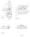
- the following operation consists in introducing a sintered block 28 into the cavity 18 in the manner shown in FIGS. 3 and 4.
- the block 28 is produced in the usual manner by sintering a powder, for example silver graphite, silver nickel, tungsten silver or metal oxide silver on a separate machine.
- the block 28 can have the final shape of the contact pad or approximately this shape or, conversely, undergo a deformation during the fixing operation. Block 28 may or may not be decarburized.
- the cavity 18 is completely filled by the sintered block and the latter forms a projection or protuberance.
- the block can also be flush with the upper face 16 of the part 10 or even be slightly recessed when the cavity 18 is not completely filled.
- This part 10 with the cavity 18 filled by the block 28 is then placed on a welding machine of which only the two upper 42 and lower 44 electrodes are shown.
- the welding machine is of a relatively common type capable of applying pressure to the treated parts while applying an electric current ensuring the heating of the parts.
- the upper electrode 42 has an imprint 45 of shape conjugate to that desired for the pellet 46 obtained by conformation of the block 28, while the lower electrode 44 has for example a stud 50 in low projection, capable of ensuring the discharge of the boss 22. It can be seen in FIG. 5, which represents the part 10 after fixing, that the stud 50 not only causes the boss 22 to be pushed back, but a depression 52 favoring the compression of the block 28 and the projection to form the pellet 46 of part 10.
- the intensity of the current must cause heating between 700 and 900 °, this intensity being for example close to 18 kiloamperes in the case of a contact piece having thickness close to 2mm, as described above.
- the duration of current flow which corresponds to the operation, is of the order of a second, and in any case extremely fast.
- the volume of the sintered block introduced into the cavity 18 is sufficient to create a protuberance, it is not essential to repress the boss 22, and the lower electrode 44 is in this case devoid of stud 50.
- This delivery operation is nevertheless essential when the cavity is only partially or completely filled by the sintered block.
- the quality of the mechanical and electrical fixing of the patch 46 to the part or support 10 is excellent.
- the pellet 46 projects from a height close to one millimeter while penetrating into the support 10 over an almost equivalent height.
- the width of the support 10 is several millimeters, for example 7 millimeters, other values being of course allowed.
- the preferred method according to the invention makes use of the discharge of the boss 22 to ensure compression and sufficient protrusion of the pellet 46, but the invention is not limited to this particular method.
- the contact piece 10 can be a fixed contact or a movable contact of a low-voltage breaking device, in particular of a circuit breaker, but the method is applicable to any other type of electrical contact, in particular of a contactor or switch.
- the block 28, introduced into the cavity 18, is a block of powder, which can be agglomerated or precompressed.
- the block 28 can also be formed on site by introducing and precompressing powder into the cavity 18.
- the part 10 with the block 28 is then placed on the welding machine in the manner described above.
- the powder sintering operation and the fixing operation are concomitant. All the aforementioned features are of course applicable to this process.
- the block of powder is compressed by a piston incorporated in the upper electrode 42 to carry out the sintering and / or fixing operation during heating.
Landscapes
- Engineering & Computer Science (AREA)
- Manufacturing & Machinery (AREA)
- Mechanical Engineering (AREA)
- Chemical & Material Sciences (AREA)
- Composite Materials (AREA)
- Materials Engineering (AREA)
- Manufacture Of Switches (AREA)
- Powder Metallurgy (AREA)
- Contacts (AREA)
Abstract
Description
- L'invention est relative à un procédé de fabrication d'une pièce composite constituée d'une pastille en matériau obtenu par agglomération de poudre principalement métallique, rendue solidaire mécaniquement et électriquement d'un support.
- Le choix des matériaux et de la surface d'un contact électrique, notamment d'un contact d'appareil de coupure dépend de nombreux facteurs, en particulier de la résistivité du matériau de contact, de la résistance mécanique et de la résistance à l'action de l'arc. Une pièce de contact du genre mentionné, constituée par un support et une pastille de contact permet de tenir compte de ces impératifs. La pastille, par exemple en alliage d'argent ou de cuivre, est généralement fabriquée séparément, par exemple par frittage, et fixée ou rapportée sur le support en cuivre, après avoir été décarburée, lorsqu'elle comporte du graphite.
- La présente invention a pour but de simplifier ce procédé de fabrication tout en améliorant la qualité des pièces de contact fabriquées.
- Le procédé de fabrication selon l'invention est caractérisé en ce que le support est préformé pour faire apparaître à l'emplacement voulu, pour la pastille une cavité, laquelle cavité forme avec une autre cavité ménagée dans l'électrode d'une machine à souder par résistance, une enceinte fermée pratiquement étanche dans laquelle est disposée un bloc de poudre précomprimée, agglomérée ou frittée, et que cette poudre est fortement comprimée par déformation du support et réduction subséquente de la cavité pendant que l'on applique un courant électrique d'intensité adéquate afin de chauffer le matériau à la température voulue pour réaliser la conformation et/ou le frittage.
- L'opération de fixation provoque simultanément la conformation ou la confirmation de la forme de la pastille par le même outil en obtenant ainsi un gain notable de temps et une amélioration de la fixation.
- Selon un mode de mise en oeuvre de l'invention, la forme de la cavité créée dans le support, est conjuguée de celle d'un bloc fritté qui y est introduit. Le support avec le bloc fritté est mis en place sur une machine à souder réalisant la fixation du bloc sur le support. La configuration de l'électrode de la machine à souder appliquée sur le bloc, détermine la forme de la pastille de contact en saillie du support au cours de l'opération de fixation. La saillie de la pastille frittée peut résulter d'une déformation du support, notamment du refoulement du bossage conjugué de la cavité. Cette déformation du support est réalisée au cours de l'opération de fixation, en utilisant une électrode appropriée pouvant simplement refouler le bossage, ou même créer un repoussement vers l'intérieur du côté opposé à la pastille. L'opération est réalisée sous pression, appliquée par les électrodes de la machine souder, cette pression étant avantageusement comprise entre 5 et 20 Kg/mm2, (1 Kg/mm2 = 98,1 bars), pour des pastilles à base d'argent. Après application de la pression, on fait passer un courant électrique par les électrodes et l'ensemble support, bloc à fritté 12 pour réaliser un échauffement provoquant l'opération de fixation. La température peut être comprise entre 700 et 900° maintenue pendant une durée d'une ou de plusieurs secondes, suffisantes à l'opération.
- Le matériau de la pastille peut être un métal pur mais est généralement un pseudo-alliage à base d'argent, notamment argent graphite, argent oxyde métallique, argent tungstène ou argent nickel. Pour certaines applications particulières, ce matériau peut être à base de cuivre, notamment cuivre tungstène ou cuivre tellure. Le support est généralement du cuivre ou un alliage de cuivre, mais l'invention est applicable à d'autres matériaux. Le procédé peut être facilement automatisé et certaines opérations peuvent être réalisées simultanément, notamment l'estampage du support et la formation de la cavité.
- Selon un autre mode de mise en oeuvre, la cavité est remplie de poudre, éventuellement précomprimée et/ou agglomérée et le frittage et la fixation sur le support sont réalisés simultanément sur la machine à souder.
- L'invention est également relative à un contact électrique réalisé par le procédé susmentionné, un tel contact électrique étant notamment utilisable dans l'appareillage électrique, notamment des disjoncteurs basse tension.
- D'autres avantages et caractéristiques ressortiront plus clairement de la description qui va suivre, d'un mode de mise en oeuvre de l'invention donné à titre d'exemple non limitatif et représenté aux dessins annexés dans lesquels :
- - la figure 1 est une vue schématique en perspective du support de contact selon l'invention ;
- - la figure 2 illustre la phase de poinçonnage du support selon la figure 1 pour former la cavité de réception du bloc fritté ;
- - les figures 3 et 4 illustrent les phases d'introduction d'un bloc fritté dans la cavité ;
- - la figure 5 montre en perspective la machine à fixer et à déformer le support;
- - la figure 6 est une vue à échelle agrandie montrant le support et le bloc en cours de fixation ;
- - la figure 7 est une vue en perspective de la pièce de contact à l'état terminé.
- - la figure 8 est une coupe longitudinale de la pièce selon la figure 7.
- Sur les figures, une pièce de contact 10, par exemple un contact d'un appareil de coupure de courant basse tension, est découpée dans une bande de cuivre ou en tout autre matériau conducteur de l'électricité, suivant un contour prédéterminé, par exemple parallélépipèdique-rectangle. Dans l'exemple illustré par les figures, l'épaisseur de la plaque de cuivre est voisine de 2mm, et la largeur voisine de 12mm, mais il est clair que l'invention est applicable à des contacts de dimensions différentes adaptées aux caractéristiques des appareils comprenant ce contact. La pièce de contact 10 est introduite entre un poinçon 12 et une matrice 14 d'une presse, susceptible de déformer la pièce 10 pour créer à l'emplacement prévu pour la pastille de contact, notamment sur la grande face latérale supérieure 16 de la pièce, une cavité 18 et sur la face opposée 20, un bossage 22. Dans l'exemple présenté, le poinçon 12 présente un téton 24 de forme conjuguée à celle de la cavité 18, ce téton 24 refoulant le matériau pour faire apparaître sur la face opposée le bossage 22. Le téton est par exemple de forme cylindrique, tandis que la matrice 14 est évidée en son centre 26 pour autoriser la formation du bossage 22. Il est clair que cette opération de préformation peut être réalisée sur la même machine que celle assurant le découpage ou l'estampage de la pièce de contact 10.
- L'opération suivante consiste à introduire un bloc fritté 28 dans la cavité 18 de la manière représentée aux figures 3 et 4. Le bloc 28 est réalisé de la manière usuelle par frittage d'une poudre par exemple d'argent graphite, d'argent nickel, d'argent tungstène ou d'argent oxyde métallique sur une machine séparée. Le bloc 28 peut avoir la forme finale de la pastille de contact ou approximativement cette forme ou inversement subir une déformation lors de l'opération de fixation. Le bloc 28 peut ou ne peut pas être décarburé. Dans l'exemple illustré, la cavité 18 est entièrement remplie par le bloc fritté et ce dernier forme une saillie ou protubérance. Le bloc peut également affleurer la face supérieure 16 de la pièce 10 ou même être en léger retrait lorsque la cavité 18 n'est pas entièrement remplie. Cette pièce 10 avec la cavité 18 remplie par le bloc 28 est ensuite placée sur une machine à souder dont seules les deux électrodes supérieure 42 et inférieure 44 sont représentées. La machine à souder est d'un type relativement courant susceptible d'appliquer une pression sur les pièces traîtées tout en appliquant un courant électrique assurant l'échauffement des pièces. L'électrode supérieure 42 présente une empreinte 45 de forme conjuguée à celle voulue pour la pastille 46 obtenue par conformation du bloc 28, tandis que l'électrode inférieure 44 présente par exemple un téton 50 en faible saillie, susceptible d'assurer le refoulement du bossage 22. On voit sur la figure 5, qui représente la pièce 10 après fixation, que le téton 50 provoque non seulement le refoulement du bossage 22, mais un enfoncement 52 favorisant la compression du bloc 28 et la venue en saillie pour former la pastille 46 de la pièce 10. Dans une des applications de l'invention, prise uniquement à titre d'illustration concrète, les électrodes 42,44 sont en tungstène et la pression est comprise entre 5 et 20 Kg/mm2 (1 Kg/mm2 = 98,1 bars) selon les caractéristiques de la pièce de contact 10. L'intensité du courant doit provoquer un échauffement compris entre 700 et 900°, cette intensité étant par exemple voisine de 18 kiloampères dans le cas d'une pièce de contact ayant une épaisseur voisine de 2mm, telle que décrite ci-dessus. La durée de passage du courant, qui correspond à l'opération, est de l'ordre de la seconde, et en tous les cas extrèmement rapide. Lorsque le volume du bloc fritté introduit dans la cavité 18 est suffisant pour créer une protubérance, il n'est pas indispensable de refouler le bossage 22, et l'électrode inférieure 44 est dans ce cas dépourvue de téton 50. Cette opération de refoulement est néanmoins indispensable lorsque la cavité n'est que partiellement ou entièrement remplie par le bloc fritté. La qualité de la fixation mécanique et électrique de la pastille 46 sur la pièce ou support 10 est excellente. A titre d'exemple, on peut préciser que la pastille 46 est en saillie d'une hauteur voisine de un millimètre tout en pénétrant dans le support 10 sur une hauteur quasi-équivalente. La largeur du support 10 est de plusieurs millimètres, par exemple de 7 millimètres, d'autres valeurs étant bien entendu admises. Le procédé préférentiel selon l'invention fait usage du refoulement du bossage 22 pour assurer une compression et une venue en saillie suffisante de la pastille 46, mais l'invention n'est pas limitée à ce procédé particulier.
- Les presses et machines à souder sont des machines standards bien connues des spécialistes, et les différentes opérations ne nécessitent aucune précaution particulière. La pièce de contact 10 peut être un contact fixe ou un contact mobile d'un appareil de coupure basse tension, notamment d'un disjoncteur, mais le procédé est applicable à tout autre type de contact électrique, notamment d'un contacteur ou interrupteur.
- Selon une variante de réalisation, le bloc 28, introduit dans la cavité 18, est un bloc de poudre, pouvant être aggloméré ou précomprimé. Le bloc 28 peut également être constitué sur place par introduction et précompression de poudre dans la cavité 18. La pièce 10 avec le bloc 28 est ensuite placée sur la machine à souder de la manière décrite ci-dessus. L'opération de frittage de la poudre et l'opération de fixation sont concomitantes. Toutes les particularités précitées sont bien entendu applicables à ce procédé.
- Selon une autre variante, le bloc de poudre est comprimé par un piston incorporé à l'électrode supérieure 42 pour réaliser l'opération de frittage et/ou de fixation lors du chauffage.
Claims (9)
Applications Claiming Priority (4)
| Application Number | Priority Date | Filing Date | Title |
|---|---|---|---|
| FR8802443 | 1988-02-25 | ||
| FR8802443A FR2627894A1 (fr) | 1988-02-25 | 1988-02-25 | Contact electrique a pastille de contact frittee et son procede de fabrication |
| FR8809277A FR2633855B1 (fr) | 1988-07-06 | 1988-07-06 | Procede de fabrication d'une piece composite et contact electrique a pastille de contact fabrique selon ce procede |
| FR8809277 | 1988-07-06 |
Publications (2)
| Publication Number | Publication Date |
|---|---|
| EP0333600A1 true EP0333600A1 (fr) | 1989-09-20 |
| EP0333600B1 EP0333600B1 (fr) | 1993-05-12 |
Family
ID=26226521
Family Applications (1)
| Application Number | Title | Priority Date | Filing Date |
|---|---|---|---|
| EP89420042A Expired - Lifetime EP0333600B1 (fr) | 1988-02-25 | 1989-02-13 | Procédé de fabrication d'une pièce composite, par exemple pour contacts électriques |
Country Status (7)
| Country | Link |
|---|---|
| US (1) | US4910868A (fr) |
| EP (1) | EP0333600B1 (fr) |
| JP (1) | JP2648360B2 (fr) |
| KR (1) | KR0153449B1 (fr) |
| CN (1) | CN1017292B (fr) |
| CA (1) | CA1335410C (fr) |
| DE (1) | DE68906445T2 (fr) |
Cited By (2)
| Publication number | Priority date | Publication date | Assignee | Title |
|---|---|---|---|---|
| WO1992019413A1 (fr) * | 1991-04-30 | 1992-11-12 | The Welding Institute | Materiau composite |
| EP3049204A1 (fr) * | 2013-09-23 | 2016-08-03 | GKN Sinter Metals Engineering GmbH | Procédé permettant de produire une pièce frittée d'une hauteur de pièce moulée précise et ensemble de pièces composé de pièces frittées assemblées |
Families Citing this family (10)
| Publication number | Priority date | Publication date | Assignee | Title |
|---|---|---|---|---|
| DE19933111A1 (de) * | 1999-07-15 | 2001-01-18 | Abb Patent Gmbh | Vakuumkammer und Verfahren zur Herstellung der Vakuumkammer |
| DE19960876A1 (de) * | 1999-12-17 | 2001-06-21 | Abb Patent Gmbh | Verfahren zur Herstellung eines Kontaktstückrohlings und eines Kontaktstückes sowie ein Kontaktstückrohling, ein Kontaktstück und eine Kontaktstückanordnung für Axialmagnetfeldanwendungen in einer Vakuumkammer |
| WO2009098836A1 (fr) * | 2008-02-08 | 2009-08-13 | Fuji Electric Fa Components & Systems Co., Ltd. | Procédé de fabrication de contact électrique et équipement de fabrication de contact électrique |
| CN102237205A (zh) * | 2010-04-27 | 2011-11-09 | 上海电科电工材料有限公司 | 一种合金铜铜嵌复银汽车电器材料及其制造方法 |
| CN102228898B (zh) * | 2011-04-25 | 2014-04-16 | 贵州大学 | 厨余垃圾处理设备 |
| CN104485261B (zh) * | 2014-10-30 | 2016-07-06 | 贵州天义电器有限责任公司 | 一种继电器接点簧片组件的焊接方法 |
| KR102371064B1 (ko) * | 2016-12-14 | 2022-03-07 | 현대자동차주식회사 | 캠 샤프트용 엔드피스 제조방법 및 그에 의해 제조되는 캠 샤프트용 엔드피스 |
| DE102017200292A1 (de) * | 2017-01-10 | 2018-07-12 | Siemens Aktiengesellschaft | Kontaktstück für einen elektrischen Schalter, elektrischer Schalter mit solch einem Kontaktstück und Verfahren zum Herstellen eines solchen Kontaktstückes |
| JP2020051962A (ja) * | 2018-09-28 | 2020-04-02 | 横河電機株式会社 | センサユニット、センサユニットを備えた伝送器、センサユニットの製造方法、および、センサユニットを備えた伝送器の製造方法 |
| DE102022203351A1 (de) | 2022-04-05 | 2023-10-05 | Siemens Aktiengesellschaft | Verfahren zum Herstellen einer elektrischen Kontaktbaugruppe sowie elektrische Kontaktbaugruppe |
Citations (4)
| Publication number | Priority date | Publication date | Assignee | Title |
|---|---|---|---|---|
| GB593171A (en) * | 1944-06-10 | 1947-10-09 | Igranic Electric Co Ltd | Improvements in or relating to electrical contacts |
| US2545352A (en) * | 1947-08-05 | 1951-03-13 | George S Gibbs | Method of making raised electrical contact points |
| FR2347800A1 (fr) * | 1976-04-09 | 1977-11-04 | Lucas Industries Ltd | Procede de realisation d'un balai pour machine dynamo-electrique |
| GB2022142A (en) * | 1977-04-20 | 1979-12-12 | Battelle Memorial Institute | Method and apparatus for manufacturing a contact layer |
Family Cites Families (10)
| Publication number | Priority date | Publication date | Assignee | Title |
|---|---|---|---|---|
| US2179960A (en) * | 1931-11-28 | 1939-11-14 | Schwarzkopf Paul | Agglomerated material in particular for electrical purposes and shaped bodies made therefrom |
| US1922162A (en) * | 1932-02-10 | 1933-08-15 | King Laboratcries Inc | Evacuation of electronic devices |
| GB444445A (en) * | 1934-05-03 | 1936-03-20 | Siemens Ag | An improved method and apparatus for the production of electric contacts |
| US2382338A (en) * | 1943-05-18 | 1945-08-14 | Stackpole Carbon Co | Electric contacts |
| US2425053A (en) * | 1944-06-23 | 1947-08-05 | Cutler Hammer Inc | Silver-backed nonwelding contact and method of making the same |
| GB749390A (en) * | 1953-08-27 | 1956-05-23 | Mallory Metallurg Prod Ltd | Improvements in and relating to the manufacture of electrical contacts |
| US3199176A (en) * | 1961-11-08 | 1965-08-10 | Texas Instruments Inc | Method of manufacturing electrical contacts |
| US3346951A (en) * | 1966-02-24 | 1967-10-17 | Talon Inc | Method of making electrical contact elements |
| JPS5942580B2 (ja) * | 1981-03-04 | 1984-10-16 | 株式会社日立製作所 | 電気接点の製造方法 |
| US4478590A (en) * | 1981-12-28 | 1984-10-23 | North American Philips Consumer Electronics Corp. | Depression cathode structure for cathode ray tubes having surface smoothness and method for producing same |
-
1989
- 1989-02-13 EP EP89420042A patent/EP0333600B1/fr not_active Expired - Lifetime
- 1989-02-13 DE DE89420042T patent/DE68906445T2/de not_active Expired - Fee Related
- 1989-02-16 US US07/311,040 patent/US4910868A/en not_active Expired - Lifetime
- 1989-02-21 CA CA000591624A patent/CA1335410C/fr not_active Expired - Fee Related
- 1989-02-23 JP JP1045025A patent/JP2648360B2/ja not_active Expired - Lifetime
- 1989-02-24 KR KR1019890002210A patent/KR0153449B1/ko not_active Expired - Fee Related
- 1989-02-25 CN CN89101159A patent/CN1017292B/zh not_active Expired
Patent Citations (4)
| Publication number | Priority date | Publication date | Assignee | Title |
|---|---|---|---|---|
| GB593171A (en) * | 1944-06-10 | 1947-10-09 | Igranic Electric Co Ltd | Improvements in or relating to electrical contacts |
| US2545352A (en) * | 1947-08-05 | 1951-03-13 | George S Gibbs | Method of making raised electrical contact points |
| FR2347800A1 (fr) * | 1976-04-09 | 1977-11-04 | Lucas Industries Ltd | Procede de realisation d'un balai pour machine dynamo-electrique |
| GB2022142A (en) * | 1977-04-20 | 1979-12-12 | Battelle Memorial Institute | Method and apparatus for manufacturing a contact layer |
Cited By (2)
| Publication number | Priority date | Publication date | Assignee | Title |
|---|---|---|---|---|
| WO1992019413A1 (fr) * | 1991-04-30 | 1992-11-12 | The Welding Institute | Materiau composite |
| EP3049204A1 (fr) * | 2013-09-23 | 2016-08-03 | GKN Sinter Metals Engineering GmbH | Procédé permettant de produire une pièce frittée d'une hauteur de pièce moulée précise et ensemble de pièces composé de pièces frittées assemblées |
Also Published As
| Publication number | Publication date |
|---|---|
| CN1017292B (zh) | 1992-07-01 |
| KR890013685A (ko) | 1989-09-25 |
| DE68906445T2 (de) | 1993-11-25 |
| KR0153449B1 (ko) | 1998-11-16 |
| US4910868A (en) | 1990-03-27 |
| CA1335410C (fr) | 1995-05-02 |
| JP2648360B2 (ja) | 1997-08-27 |
| EP0333600B1 (fr) | 1993-05-12 |
| DE68906445D1 (de) | 1993-06-17 |
| CN1036526A (zh) | 1989-10-25 |
| JPH0210615A (ja) | 1990-01-16 |
Similar Documents
| Publication | Publication Date | Title |
|---|---|---|
| EP0333600B1 (fr) | Procédé de fabrication d'une pièce composite, par exemple pour contacts électriques | |
| EP0658946A1 (fr) | Plaque d'électrode à support de type mousse métallique pour générateur électrochimique et procédé pour fabriquer une telle plaque d'électrode | |
| JPWO2009041246A1 (ja) | 接点部材の製造方法、接点部材および開閉器 | |
| CN100365747C (zh) | 一种低压电器用的电触头材料 | |
| FR2472826A1 (fr) | Procede pour confectionner un contact electrique composite soude in situ sur un support metallique, et dispositif correspondant | |
| FR2633855A1 (fr) | Procede de fabrication d'une piece composite et contact electrique a pastille de contact fabrique selon ce procede | |
| US4366361A (en) | Method of producing an electrical component | |
| JP2012248490A (ja) | 浮動接点を有する温度ヒューズ | |
| FR2627894A1 (fr) | Contact electrique a pastille de contact frittee et son procede de fabrication | |
| EP0038243B1 (fr) | Profilé métallique pour la réalisation d'un élément conducteur, procédé de réalisation de cet élément conducteur et élément conducteur réalisé par ce procédé | |
| JP3413167B2 (ja) | 小型ブレーカの製造方法 | |
| US8282432B2 (en) | Weld terminal, switch assembly and methods of attachment | |
| EP0118345B1 (fr) | Pièce de contact électrique et son procédé de fabrication | |
| FR3100935A1 (fr) | Procede et installation de fabrication de sous-ensembles de connexion electrique | |
| FR2914107A1 (fr) | Commutateur inverseur. | |
| FR2842659A1 (fr) | Procede d'amelioration d'une liaison entre un contact et des brins d'un cable | |
| JPH08181358A (ja) | 熱電変換素子並びにその製造方法及びその製造装置 | |
| FR2780562A1 (fr) | Procede de realisation d'une piece contactee | |
| FR2890487A1 (fr) | Procede de fabrication d'un contact electrique, contact electrique fabrique selon ce procede et appareil electrique comportant un tel contact | |
| FR2612341A1 (fr) | Procede pour la realisation d'une cosse de tresse de connexion electrique et connexion ainsi realisee | |
| JP2006140737A (ja) | 水晶振動子とその製造方法 | |
| JPS5923323Y2 (ja) | 回路しや断器の接触子 | |
| JP3026247B2 (ja) | 熱圧着ジョイント装置 | |
| FR2809539A1 (fr) | Procede de montage d'une disposition de contacts, en particulier pour connecter les batteries dans les telephones mobiles et disposition contacts | |
| JPH01143176A (ja) | 端子等の製造方法 |
Legal Events
| Date | Code | Title | Description |
|---|---|---|---|
| PUAI | Public reference made under article 153(3) epc to a published international application that has entered the european phase |
Free format text: ORIGINAL CODE: 0009012 |
|
| AK | Designated contracting states |
Kind code of ref document: A1 Designated state(s): BE CH DE ES GB IT LI |
|
| 17P | Request for examination filed |
Effective date: 19900208 |
|
| 17Q | First examination report despatched |
Effective date: 19920210 |
|
| GRAA | (expected) grant |
Free format text: ORIGINAL CODE: 0009210 |
|
| AK | Designated contracting states |
Kind code of ref document: B1 Designated state(s): BE CH DE ES GB IT LI |
|
| REF | Corresponds to: |
Ref document number: 68906445 Country of ref document: DE Date of ref document: 19930617 |
|
| ITF | It: translation for a ep patent filed | ||
| PG25 | Lapsed in a contracting state [announced via postgrant information from national office to epo] |
Ref country code: ES Free format text: LAPSE BECAUSE OF FAILURE TO SUBMIT A TRANSLATION OF THE DESCRIPTION OR TO PAY THE FEE WITHIN THE PRESCRIBED TIME-LIMIT Effective date: 19930823 |
|
| GBT | Gb: translation of ep patent filed (gb section 77(6)(a)/1977) |
Effective date: 19930729 |
|
| PGFP | Annual fee paid to national office [announced via postgrant information from national office to epo] |
Ref country code: CH Payment date: 19970220 Year of fee payment: 9 |
|
| PGFP | Annual fee paid to national office [announced via postgrant information from national office to epo] |
Ref country code: ES Payment date: 19970227 Year of fee payment: 9 |
|
| PGFP | Annual fee paid to national office [announced via postgrant information from national office to epo] |
Ref country code: BE Payment date: 19970410 Year of fee payment: 9 |
|
| PG25 | Lapsed in a contracting state [announced via postgrant information from national office to epo] |
Ref country code: LI Free format text: LAPSE BECAUSE OF NON-PAYMENT OF DUE FEES Effective date: 19980228 Ref country code: CH Free format text: LAPSE BECAUSE OF NON-PAYMENT OF DUE FEES Effective date: 19980228 Ref country code: BE Free format text: LAPSE BECAUSE OF NON-PAYMENT OF DUE FEES Effective date: 19980228 |
|
| BERE | Be: lapsed |
Owner name: MERLIN GERIN Effective date: 19980228 |
|
| REG | Reference to a national code |
Ref country code: CH Ref legal event code: PL |
|
| PGFP | Annual fee paid to national office [announced via postgrant information from national office to epo] |
Ref country code: GB Payment date: 20000209 Year of fee payment: 12 |
|
| PGFP | Annual fee paid to national office [announced via postgrant information from national office to epo] |
Ref country code: DE Payment date: 20010201 Year of fee payment: 13 |
|
| PG25 | Lapsed in a contracting state [announced via postgrant information from national office to epo] |
Ref country code: GB Free format text: LAPSE BECAUSE OF NON-PAYMENT OF DUE FEES Effective date: 20010213 |
|
| GBPC | Gb: european patent ceased through non-payment of renewal fee |
Effective date: 20010213 |
|
| PG25 | Lapsed in a contracting state [announced via postgrant information from national office to epo] |
Ref country code: DE Free format text: LAPSE BECAUSE OF NON-PAYMENT OF DUE FEES Effective date: 20020903 |
|
| PG25 | Lapsed in a contracting state [announced via postgrant information from national office to epo] |
Ref country code: IT Free format text: LAPSE BECAUSE OF NON-PAYMENT OF DUE FEES;WARNING: LAPSES OF ITALIAN PATENTS WITH EFFECTIVE DATE BEFORE 2007 MAY HAVE OCCURRED AT ANY TIME BEFORE 2007. THE CORRECT EFFECTIVE DATE MAY BE DIFFERENT FROM THE ONE RECORDED. Effective date: 20050213 |
|
| PLBE | No opposition filed within time limit |
Free format text: ORIGINAL CODE: 0009261 |
|
| STAA | Information on the status of an ep patent application or granted ep patent |
Free format text: STATUS: NO OPPOSITION FILED WITHIN TIME LIMIT |