EP0333631A1 - Dispositif pour empiler des treillis d'acier pour béton armé - Google Patents
Dispositif pour empiler des treillis d'acier pour béton armé Download PDFInfo
- Publication number
- EP0333631A1 EP0333631A1 EP89630053A EP89630053A EP0333631A1 EP 0333631 A1 EP0333631 A1 EP 0333631A1 EP 89630053 A EP89630053 A EP 89630053A EP 89630053 A EP89630053 A EP 89630053A EP 0333631 A1 EP0333631 A1 EP 0333631A1
- Authority
- EP
- European Patent Office
- Prior art keywords
- mats
- stacking
- stacking machine
- arms
- bars
- Prior art date
- Legal status (The legal status is an assumption and is not a legal conclusion. Google has not performed a legal analysis and makes no representation as to the accuracy of the status listed.)
- Withdrawn
Links
- 229910000831 Steel Inorganic materials 0.000 title abstract description 13
- 239000010959 steel Substances 0.000 title abstract description 13
- 238000010276 construction Methods 0.000 title abstract description 5
- 239000002184 metal Substances 0.000 claims abstract description 4
- 238000003466 welding Methods 0.000 claims description 7
- 229910000746 Structural steel Inorganic materials 0.000 claims description 2
- 238000006073 displacement reaction Methods 0.000 abstract description 2
- 101100495270 Caenorhabditis elegans cdc-26 gene Proteins 0.000 description 4
- 239000004567 concrete Substances 0.000 description 4
- 230000002787 reinforcement Effects 0.000 description 2
- 229910001294 Reinforcing steel Inorganic materials 0.000 description 1
- 238000005452 bending Methods 0.000 description 1
- 230000001419 dependent effect Effects 0.000 description 1
- 238000009415 formwork Methods 0.000 description 1
- 238000011065 in-situ storage Methods 0.000 description 1
- 230000003993 interaction Effects 0.000 description 1
- 238000004519 manufacturing process Methods 0.000 description 1
- 239000011150 reinforced concrete Substances 0.000 description 1
- 230000003014 reinforcing effect Effects 0.000 description 1
Images

Classifications
-
- B—PERFORMING OPERATIONS; TRANSPORTING
- B21—MECHANICAL METAL-WORKING WITHOUT ESSENTIALLY REMOVING MATERIAL; PUNCHING METAL
- B21F—WORKING OR PROCESSING OF METAL WIRE
- B21F33/00—Tools or devices specially designed for handling or processing wire fabrics or the like
- B21F33/002—Coiling or packing wire network
-
- B—PERFORMING OPERATIONS; TRANSPORTING
- B65—CONVEYING; PACKING; STORING; HANDLING THIN OR FILAMENTARY MATERIAL
- B65G—TRANSPORT OR STORAGE DEVICES, e.g. CONVEYORS FOR LOADING OR TIPPING, SHOP CONVEYOR SYSTEMS OR PNEUMATIC TUBE CONVEYORS
- B65G57/00—Stacking of articles
- B65G57/02—Stacking of articles by adding to the top of the stack
- B65G57/08—Stacking of articles by adding to the top of the stack articles being tilted or inverted prior to depositing
- B65G57/081—Stacking of articles by adding to the top of the stack articles being tilted or inverted prior to depositing alternate articles being inverted
Definitions
- the invention relates to a stacking machine for structural steel mats according to the preamble of claim 1.
- Steel mats consist of reinforcing bars crossing at right angles with a smooth, profiled or ribbed surface with diameters of up to 16 mm, which are connected to each other at the crossing points by resistance spot welding.
- the mats are used today in almost all areas of high and low reinforced concrete construction.
- the steel mesh has become a mass product.
- Reinforcing steel mats replace a large part of the manual work required for laying very cost-effectively with automatic production in the factory. The cost advantage is greatest, especially in the case of flat components such as ceilings, floor slabs, concrete roadways, where only a small amount of additional cutting and bending is required.
- Another advantageous field of application is the prefabricated construction, in which steel mats are placed in a formwork which is then poured out with concrete or gas concrete. These steel mats have fixed lengths and widths that are significantly smaller than those of the mats used in in-situ concrete construction; in addition, the reinforcement bars have a diameter of only about 5 mm. The mats therefore have a relatively large volume / weight factor. For transport reasons, the mats are stacked in such a way that the cross bars of two adj beard mats come to lie next to each other. Every second mat coming out of the resistance welding machine is therefore turned over before it is placed on the stack. In addition, a resistance welding machine with two tracks is usually used and the mats produced are placed on a single stack.
- the object of the present invention is to create a stacking machine which permits such stacking. This object is achieved by the invention specified in claim 1. Advantageous embodiments of the invention are specified in the dependent claims.
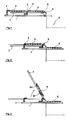
- FIG. 1 shows a bar 1 which can be moved in the direction of the arrow over approximately half its length.
- Two driver pins 2, 3 are fastened to the beam by means of screwing.
- a sheet metal table 8 there are two steel mats 4, 5.
- This table has elongated slots through which the driving pins 2 and 3 can move freely.
- an arm 7 is shown, which is attached to a rotatable shaft 6.
- slots are provided in the sheet metal table, so that the arms 7 can freely rotate from their illustrated rest position by approximately 180 ° in the clockwise direction to the stacking position 9.
- a lever arm 64 for example, on which a hydraulic motor 63 acts (see FIG.
- the stacking machine can be adapted to the new conditions in just a few minutes - adjusting the driving pins 2, 3 on the bar and entering the new data into the computer.
- the sheet table 8 is approximately at the level at which the mats come out of the tracks 60, 61 of the welding machine (see FIG. 6). Between the latter and the stacking machine, a set of driven rollers 62 is arranged, which convey the steel mats into the desired position on the table 8 next to the stacking position 9.
- the arms 7 In the last position shown (see FIG. 4) of the stacking machine, the arms 7 have rotated about 180 °. The steel mat 4 is still held on the arms 7 while the mat 5 is on the stack.
- the usual guide elements 40 are also indicated here, which prevent the mats from breaking out during the free fall and ensure an integrity stack. Such elements are advantageous but not absolutely necessary. After releasing the mat, the arms 7 move back into their starting position and the next two mats can be pushed onto the table 9.
- the hook 5 consists essentially of two hooks, one (reference numeral 50) at the level of outermost longitudinal rod of the mat 4, on which the arm 7 is fastened and the second (reference numeral 52) can be moved via an air pressure cylinder 51. Both hooks are slightly curved in the direction of the longitudinal bars to be clamped. In order not to impair the longitudinal displacement of the mats 4 out of the welding machine, the hooks 50, 52 are located just below the table level. When the shaft 6 rotates, the mat comes to rest on the arms and slides a few centimeters until it rests on the hook 50; then the air pressure cylinder 51 is pressurized and the hook 52 clamps the mat.
- the air pressure which ensures a firm hold of the mat on the arm without damaging the rods / welding points, is determined by simple tests. Since the air pressure cylinder can move the hook 52 over a greater distance, there is in principle the possibility of clamping mats with different rod spacings without adjusting the hook 50 and the air pressure cylinder 51. In order to prevent the hook from breaking out laterally, it can be advantageous for heavy mats to be attached to a trolley; the rollers are guided in a longitudinal rail attached to the arm 7.
- electromagnets can also be used. However, it must be taken into account here that these magnetize the mats, which is undesirable for many customers.
- the same reference numerals have been used as before, so that further explanations are unnecessary. It should also be noted here that the functional interaction of the parts is to be explained but their relative dimensions are incorrect.
- the machine has three bars 1 and three rotating arms 7 provided with clamping devices; As can be seen from the stack 9, the mats have the nominal width but only about 2/3 of the length for which the machine is designed. A part of the sheet table 8 has been omitted to show the rotating arm 6.
Landscapes
- Engineering & Computer Science (AREA)
- Mechanical Engineering (AREA)
- Stacking Of Articles And Auxiliary Devices (AREA)
Applications Claiming Priority (2)
| Application Number | Priority Date | Filing Date | Title |
|---|---|---|---|
| LU87174 | 1988-03-18 | ||
| LU87174A LU87174A1 (de) | 1988-03-18 | 1988-03-18 | Stapelmaschine fuer baustahlmatten |
Publications (1)
| Publication Number | Publication Date |
|---|---|
| EP0333631A1 true EP0333631A1 (fr) | 1989-09-20 |
Family
ID=19731033
Family Applications (1)
| Application Number | Title | Priority Date | Filing Date |
|---|---|---|---|
| EP89630053A Withdrawn EP0333631A1 (fr) | 1988-03-18 | 1989-03-17 | Dispositif pour empiler des treillis d'acier pour béton armé |
Country Status (2)
| Country | Link |
|---|---|
| EP (1) | EP0333631A1 (fr) |
| LU (1) | LU87174A1 (fr) |
Cited By (2)
| Publication number | Priority date | Publication date | Assignee | Title |
|---|---|---|---|---|
| WO2004007109A1 (fr) * | 2002-07-15 | 2004-01-22 | Beta Systems Srl | Dispositif de formation automatique de paquets de panneaux de mailles electro-soudees et procede associe |
| KR20200131986A (ko) * | 2019-05-15 | 2020-11-25 | 유한회사 상관철망 | 철망 적재장치 |
Citations (3)
| Publication number | Priority date | Publication date | Assignee | Title |
|---|---|---|---|---|
| AT239037B (de) * | 1963-09-02 | 1965-03-10 | Evg Entwicklung Verwert Ges | Vorrichtung zum Wenden und Stapeln von aus Schweißautomaten austretenden geschweißten Gittermatten |
| AT366937B (de) * | 1978-11-08 | 1982-05-25 | Evg Entwicklung Verwert Ges | Vorrichtung zum maschinellen stapeln von gittermatten unter abwechselndem wenden derselben |
| DE3237255A1 (de) * | 1982-10-08 | 1984-04-12 | Reinking Maschinenbau GmbH, 4993 Rahden | Verfahren zum maschinellen stapeln von aus einer gitterschweissmaschine austretenden gittermatten und vorrichtung zur durchfuehrung des verfahrens |
-
1988
- 1988-03-18 LU LU87174A patent/LU87174A1/de unknown
-
1989
- 1989-03-17 EP EP89630053A patent/EP0333631A1/fr not_active Withdrawn
Patent Citations (3)
| Publication number | Priority date | Publication date | Assignee | Title |
|---|---|---|---|---|
| AT239037B (de) * | 1963-09-02 | 1965-03-10 | Evg Entwicklung Verwert Ges | Vorrichtung zum Wenden und Stapeln von aus Schweißautomaten austretenden geschweißten Gittermatten |
| AT366937B (de) * | 1978-11-08 | 1982-05-25 | Evg Entwicklung Verwert Ges | Vorrichtung zum maschinellen stapeln von gittermatten unter abwechselndem wenden derselben |
| DE3237255A1 (de) * | 1982-10-08 | 1984-04-12 | Reinking Maschinenbau GmbH, 4993 Rahden | Verfahren zum maschinellen stapeln von aus einer gitterschweissmaschine austretenden gittermatten und vorrichtung zur durchfuehrung des verfahrens |
Cited By (3)
| Publication number | Priority date | Publication date | Assignee | Title |
|---|---|---|---|---|
| WO2004007109A1 (fr) * | 2002-07-15 | 2004-01-22 | Beta Systems Srl | Dispositif de formation automatique de paquets de panneaux de mailles electro-soudees et procede associe |
| CN1297361C (zh) * | 2002-07-15 | 2007-01-31 | 倍塔赛斯特姆有限公司 | 电焊网板组的自动成型设备及相关方法 |
| KR20200131986A (ko) * | 2019-05-15 | 2020-11-25 | 유한회사 상관철망 | 철망 적재장치 |
Also Published As
| Publication number | Publication date |
|---|---|
| LU87174A1 (de) | 1989-10-26 |
Similar Documents
| Publication | Publication Date | Title |
|---|---|---|
| DE4396373B4 (de) | Bindevorrichtung, Magazin, Gerät und Verfahren hierzu, sowie die Bindevorrichtung aufweisendes Stahlbeton-Bauwerk | |
| DE2744235C2 (fr) | ||
| EP1179415B1 (fr) | Dispositif longitudinal pour le travail de carton ondulé | |
| DE2159714C3 (de) | Vorrichtung zum Trennen von durch horizontale Schnitte abgegrenzten, nach dem Härten zu einem Stapel zusammenhaftenden Gasbetonelementen | |
| DE2627845C2 (de) | Verfahren und Vorrichtung zum Setzen von Schwellen auf das Schotterbett eines Gleises | |
| DE2952026A1 (de) | Biegemaschine zum gleichzeitigen biegen von betonstahldraehten bei baustahlmatten | |
| DE69700291T2 (de) | Vorrichtung zum Ablängen und Formen von Stahlstäben, insbesondere von Betonbewehrungsstäben | |
| DE3331341C2 (de) | Vorrichtung zum Quertransport eines Profilstabes für Profilstab-Bearbeitungsstraßen mit Längstransport-Rollgang | |
| DE2911735A1 (de) | Bogenanleger | |
| DE2947581A1 (de) | Blechschneidevorrichtung | |
| EP0333631A1 (fr) | Dispositif pour empiler des treillis d'acier pour béton armé | |
| DE3941291A1 (de) | Biegeanlage fuer stahlstaebe | |
| EP0414061B1 (fr) | Dispositif pour retirer une barre métallique d'un faisceau de barres | |
| DD239735A5 (de) | Betaetigungsvorrichtung zur automatischen betaetigung von lasten | |
| DE2446768C3 (de) | Vorrichtung zum Einrütteln von Dübeln in Straßendecken aus Beton | |
| EP0094929A1 (fr) | Procédé et dispositif pour subdiviser par coupe une nappe de treillis composée de fils croisés rectangulaires | |
| DE2627058A1 (de) | Anschlagvorrichtung zum positionieren eines bleches auf einer werkzeugmaschine | |
| DE3312416C2 (de) | Vorrichtung zum Verlegen von plattenförmigen Elementen | |
| CH687008A5 (de) | Biegevorrichtung fuer die Laengsdrahtenden von Bewehrungsgittern fuer Betonplatten. | |
| DE3220805C2 (de) | Papierbogen-Zusammentragmaschine | |
| DE4305825C2 (de) | Einrichtung zum Verlegen von Verbundsteinen | |
| DE3808754C2 (de) | Verfahren zum Einbringen von Preßpfählen und Spunddielen | |
| EP0439665B1 (fr) | Machine à souder pour largets | |
| DE497749C (de) | Vorrichtung zur Anbringung von Binderhaken in Bauplatten aus Stroh | |
| AT225403B (de) | Formatsäge |
Legal Events
| Date | Code | Title | Description |
|---|---|---|---|
| PUAI | Public reference made under article 153(3) epc to a published international application that has entered the european phase |
Free format text: ORIGINAL CODE: 0009012 |
|
| AK | Designated contracting states |
Kind code of ref document: A1 Designated state(s): AT BE CH DE FR IT LI NL |
|
| STAA | Information on the status of an ep patent application or granted ep patent |
Free format text: STATUS: THE APPLICATION IS DEEMED TO BE WITHDRAWN |
|
| 18D | Application deemed to be withdrawn |
Effective date: 19900321 |