EP0333901A1 - Système de commande pour un miroir rétroviseur extérieur pliable - Google Patents
Système de commande pour un miroir rétroviseur extérieur pliable Download PDFInfo
- Publication number
- EP0333901A1 EP0333901A1 EP88104665A EP88104665A EP0333901A1 EP 0333901 A1 EP0333901 A1 EP 0333901A1 EP 88104665 A EP88104665 A EP 88104665A EP 88104665 A EP88104665 A EP 88104665A EP 0333901 A1 EP0333901 A1 EP 0333901A1
- Authority
- EP
- European Patent Office
- Prior art keywords
- electric motor
- control system
- trigger
- rearview mirror
- pulse
- Prior art date
- Legal status (The legal status is an assumption and is not a legal conclusion. Google has not performed a legal analysis and makes no representation as to the accuracy of the status listed.)
- Granted
Links
- 230000009977 dual effect Effects 0.000 claims 1
- 239000003990 capacitor Substances 0.000 description 10
- 230000003111 delayed effect Effects 0.000 description 3
- 230000000712 assembly Effects 0.000 description 2
- 238000000429 assembly Methods 0.000 description 2
- 238000010586 diagram Methods 0.000 description 2
- 241001481828 Glyptocephalus cynoglossus Species 0.000 description 1
- 230000007935 neutral effect Effects 0.000 description 1
Images


Classifications
-
- B—PERFORMING OPERATIONS; TRANSPORTING
- B60—VEHICLES IN GENERAL
- B60R—VEHICLES, VEHICLE FITTINGS, OR VEHICLE PARTS, NOT OTHERWISE PROVIDED FOR
- B60R1/00—Optical viewing arrangements; Real-time viewing arrangements for drivers or passengers using optical image capturing systems, e.g. cameras or video systems specially adapted for use in or on vehicles
- B60R1/02—Rear-view mirror arrangements
- B60R1/06—Rear-view mirror arrangements mounted on vehicle exterior
- B60R1/062—Rear-view mirror arrangements mounted on vehicle exterior with remote control for adjusting position
- B60R1/07—Rear-view mirror arrangements mounted on vehicle exterior with remote control for adjusting position by electrically powered actuators
- B60R1/074—Rear-view mirror arrangements mounted on vehicle exterior with remote control for adjusting position by electrically powered actuators for retracting the mirror arrangements to a non-use position alongside the vehicle
Definitions
- This invention relates to a control system for a foldable outside rearview mirror for a motor vehicle, and more particularly, the invention relates to an outside rearview mirror which can be folded both of forwardly and backwardly by a remote control from inside of the motor vehicle.
- a foldable rearview mirror of this type is generally erected or folded by swinging a mirror body when an electric motor for folding the rearview mirror mounted in the mirror body is driven by operating switches provided in the compartment of the motor vehicle.
- a control system which is composed of a seesaw type changeover switch, a pair of timer circuits for outputting ON signals only for a predetermined time upon receipt of an output signal from the switches to erect and fold a rearview mirror to a predetermined position, and a relay circuit for switching the polarity of the power source of an electric motor for driving the rearview mirror upon receipt on ON/OFF by the timer circuits.
- the operation switch is limited to the seesaw type changeover switch, the electric motor is caused to stop because of the output terminal of the relay being shortcircuited when the switch is operated during the operation of the timer circuits of the mirror body might be rotated in an opposite direction after the electric motor is gradually stopped.
- the control system of the invention for the foldable outside rearview mirror driven by an electric motor comprises: an operation switch; trigger means for outputting a trigger pulse by said operation switch; timer means for outputting a pulse of a predeterminded pulse width to drive the electric motor only for a set time upon receipt of the trigger pulse from the trigger means; polarity changing means for reversely switching the drive of the electric motor by inverting a pair of the outputs of high and low levels upon receipt of the trigger pulse from the trigger means; switching means for switching a voltage applied to the electric motor means to erect or fold the rearview mirror upon receipt of the output of the polarity changing means; and an electric motor circuit.
- An automatic reset one-touch type push-button switch is employed as an operation switch.
- the changing means and the timer means are operated through the trigger means by the operation switch, and the electric motor is operated in the polarity (for erecting or folding the mirror) set by the changing means for a period of time set by the timer means to erect or fold the rearview mirror to a predetermined position. Further, when the operation switch is operated during the operation of the timer, the electric motor is reversed to reverse the swinging operation of the rearview mirror immediately.
- the motor means includes the electric motor for swinging the mirror body and a limit switch group for stopping the electric motor when the mirror body is rotated to a predetermined position.
- FIG. 1 there is shown an outside rearview mirror assembly suitable to be associated with a motor vehicle.
- This system includes an operation switch 10 of an automatic reset type one-touch button switch provided in a compartment, a controller 30, right and left mirror assemblies 11 and motor circuits 51, 52 (Fig. 2).
- Each mirror assembly 11 includes a shaft 15 standing on the extension 14 of a base 13, a frame 16 rotatably supported on and by the shaft 15, a mirror body 17, a gear box 18 provided in the rotary portion of the frame 16 near the shaft, a reduction gear mechanism 19 contained in the gear box 18 and an electric motor 20 secured to the top of the gear box 18 for electrically folding the mirror body.
- Fig. 1 only shows the right mirror assembly for simplicity of illustration and the left mirror assembly is omitted therefrom.
- the reduction gear mechanism 19 is composed of a reduction gear train coupled to a worm gear 21 on the output shaft of the electric motor 20 and an end gear 22 is engaged in meshing contact with a clutch gear 23 mounted on the shaft 15.
- the clutch gear 23 is energized or urged towards a clutch gear retainer 25 secured to the upper end portion of the shaft, by means of the elasticity of a helical spring 24.
- the clutch gear 23 engaged in meshing contact witch the end gear 22 is mounted on the shaft 15 by means of the elasticity of the spring 24, the clutch gear 23 remains secured to the shaft 15 when a predetermined rotary torque or less is applied thereto.
- the rotary force of the end gear 22 is converted to a rotary motion with centering around the shaft 15, and thereby the mirror body 17 is rotated in a folding direction by the movements of said gear 22.
- the electric motor 20 is reversely rotated, the mirror body is swung from the folded position towards the erected position to return to the original position.
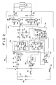
- Fig. 2 is a schematic diagram of the control system.
- the controller 30 is connected, at the input side thereof, with the operation switch 10, an ignition switch 27 and a battery 28, while the motor circuits 51, 52 are connected to the output side of the controller 30.
- the controller 30 includes a constant-voltage circuit 31, a chatter preventing circuit 32, a delay circuit 33, a trigger circuit 35, a polarity changing circuit 36, a timer circuit 37 and a switching circuit 40.
- the motor circuits 51 and 52 are respectively associated to the right and left mirror assemblies.
- Each motor circuit includes one of the electric motors 20 for folding the mirror body 17 in the folding direction when a current flows from a contact 43 to a contact 44, and for erecting the mirror body 17 when the current flows reversely from the contact 44 to the contact 43.
- Said motor circuits also include limit switch groups (not shown) for energizing or deenergizing the motor circuits 51, 52 when the mirror body 17 has reached a predetermined folded or erected position by driving the respective motor 20.
- the trigger circuit 35 includes a flip-flop IC1 1/2, a resistor R11 and a capacitor C5 connected to a reset terminal R1 of the flip-flop.
- a pulse for an operation signal may be inputted form the automatic reset one-touch type push-button 10 through the chatter preventing circuit 32 to the input terminal CP1 of the IC1 1/2.
- the output of the first output terminal Q1 of the IC1 1/2 is returned to the reset terminal R1 through the resistor R11 and delayed by the capacitor C5.
- the flip-flop is reset after a short time to output a trigger pulse having a narrow pulse width. This pulse is inputted to the input terminal CP2 of a FF IC1 2/2 which constitutes the polarity changing circuit 36, and to the input terminal A of a timer IC2.
- the IC1 2/2 produces outputs Q2, Q2 every time the trigger output Q1 of the IC1 1/2 is inputted to the input terminal CP2 of the IC1 2/2.
- Diodes D4 to D7 are connected in parallel to the output side of the IC1 2/2 and connected to the output terminal Q of the timer IC2 through resistors R7, R8 connected to the dividing points K1, K2, of the diodes D4 and D5, D6 and D7, respectively.
- the timer cirucuit 37 includes the timer IC2 which is a retriggerable nonostable multivibrator, a resistor R6, a capacitor C4 and a diode D8 connected to the side of terminals T1, T2 as shown in the drawing, and a voltage applied to the input terminal CD rises, delayed by the resistor R5 and the capacitor C3, to the supplied voltage V DD at the initial state of connecting the battery (Fig. 3).
- the output pulse width of the first output terminal Q can be set to a predetermined value tw (outputting time) by the resistor R6 and the capacitor C4 connected to the terminals T1, T2, and said output pulse is applied to the dividing points K1, K2 of the input side of the switching circuit 40.
- the switching circuit 40 includes transistors TR1, TR2 which operate upon receipt of an input signal "H" at the bases from the points K1, K2 of the input side, and relays 41, 42 connected to said transistors to switch the normal or reverse rotation of the motor of folding or errecting the mirror by driving the motor circuits 51, 52 through the relay contacts 43, 44.
- the automatic reset type one-touch push-button switch 10 is operated to generate a pulse having a predetermined width (approx. several microseconds) form the output terminal Q1 of the FF IC1 1/2 of the trigger circuit 35. Then, the outputs Q2, Q2 of the FF IC1 2/2 for changing the polarity are inverted at the same time by the rise of a pulse, and the output Q of the timer IC2 is set to a predetermined time (e.g., 15 ⁇ 5 sec.) determined by the capacitor C4 and the resistor R6, and the transistors TR1, TR2 are alternately operated via the diodes D4 ot D7. In this manner, the relay 41 or 42 is switched to switch the normal or reverse rotation of the electic motor connected externally.
- a predetermined time e.g. 15 ⁇ 5 sec.
- the output Q of the IC2 Since the input of the input terminal CD of the timer IC2 rises delayed by a time t2 with reference to the B input by means of the delay circuit 33 when the battery is connected, the output Q of the IC2 is always set to "L" level in an initial state. If the output of the first output terminal Q1 is "H", the FF IC1 1/2 is momentarily reset after a time t1 by the pulse (having a width of several microseconds) determined by the time constant of the resistor R11 and the capacitor C5. Thus, the output of the terminal Q1 of the IC1 1/2 becomes “L” again still in the initial state.
- the output Q1 of the IC1 1/2 becomes "H" to momentarily generate a pulse having a width of several microseconds as described above.
- the output terminals Q2, Q2 , of the IC1 2/2 are inverted substantially at the same time irrespective of the operated time of the switch 10 and the magnitudes of the resistor R3 and the capacitor C2 of the chatter preventing circuit 32 and the pulse"H" having the predetermined time tw determined by the capacitor C4 and the resistor R6 can be outputted from the terminal Q of IC2.
- the rotating direction of the electric motor is reversed. For instance, the electric motor is switched from folding to erecting the mirror body, and thereafter the mirrorbody is continuously erected for the time tw.
- the electric motor-driven foldable door mirror is not limited for its operation switch to a seesaw type changeover switch and the disadvantage of a shortcircuit at the output of the relay according to the time of switching the operation switch is prevented.
- the rearview mirror is prevented from unnatural operation even by any type of the operation switch and capable of being optionally switched and inverted in folding or erecting the mirror body.
Landscapes
- Engineering & Computer Science (AREA)
- Multimedia (AREA)
- Mechanical Engineering (AREA)
- Rear-View Mirror Devices That Are Mounted On The Exterior Of The Vehicle (AREA)
Priority Applications (2)
| Application Number | Priority Date | Filing Date | Title |
|---|---|---|---|
| EP19880104665 EP0333901B1 (fr) | 1988-03-23 | 1988-03-23 | Système de commande pour un miroir rétroviseur extérieur pliable |
| DE19883850490 DE3850490T2 (de) | 1988-03-23 | 1988-03-23 | Steuerungssystem für einen einklappbaren Aussen-Rückspiegel. |
Applications Claiming Priority (1)
| Application Number | Priority Date | Filing Date | Title |
|---|---|---|---|
| EP19880104665 EP0333901B1 (fr) | 1988-03-23 | 1988-03-23 | Système de commande pour un miroir rétroviseur extérieur pliable |
Publications (2)
| Publication Number | Publication Date |
|---|---|
| EP0333901A1 true EP0333901A1 (fr) | 1989-09-27 |
| EP0333901B1 EP0333901B1 (fr) | 1994-06-29 |
Family
ID=8198835
Family Applications (1)
| Application Number | Title | Priority Date | Filing Date |
|---|---|---|---|
| EP19880104665 Expired - Lifetime EP0333901B1 (fr) | 1988-03-23 | 1988-03-23 | Système de commande pour un miroir rétroviseur extérieur pliable |
Country Status (2)
| Country | Link |
|---|---|
| EP (1) | EP0333901B1 (fr) |
| DE (1) | DE3850490T2 (fr) |
Cited By (5)
| Publication number | Priority date | Publication date | Assignee | Title |
|---|---|---|---|---|
| FR2663595A1 (fr) * | 1990-06-26 | 1991-12-27 | Baron Laurent | Retroviseur exterieur et dispositif de protection. |
| EP0548938A1 (fr) * | 1991-12-26 | 1993-06-30 | Murakami Kaimeido Co., Ltd | Rétroviseurs rabattables électriquement |
| EP0587994A1 (fr) * | 1992-09-16 | 1994-03-23 | Murakami Kaimeido Co., Ltd | Rétroviseur extérieur repliable électriquement pour véhicules automobiles |
| WO2000047447A1 (fr) * | 1999-02-10 | 2000-08-17 | Magna Reflex Holding Gmbh | Retroviseur exterieur pour vehicule et procede de reglage y relatif |
| US6711855B1 (en) | 1999-05-05 | 2004-03-30 | Atoma International Corporation | Power drive mechanism for a motor vehicle liftgate having a disengageable gear train |
Citations (2)
| Publication number | Priority date | Publication date | Assignee | Title |
|---|---|---|---|---|
| GB2155876A (en) * | 1984-02-27 | 1985-10-02 | Tokai Rika Co Ltd | A door mirror |
| GB2159782A (en) * | 1984-06-05 | 1985-12-11 | Hewitt Delbert C | Side view mirror for vehicles |
-
1988
- 1988-03-23 EP EP19880104665 patent/EP0333901B1/fr not_active Expired - Lifetime
- 1988-03-23 DE DE19883850490 patent/DE3850490T2/de not_active Expired - Fee Related
Patent Citations (2)
| Publication number | Priority date | Publication date | Assignee | Title |
|---|---|---|---|---|
| GB2155876A (en) * | 1984-02-27 | 1985-10-02 | Tokai Rika Co Ltd | A door mirror |
| GB2159782A (en) * | 1984-06-05 | 1985-12-11 | Hewitt Delbert C | Side view mirror for vehicles |
Non-Patent Citations (2)
| Title |
|---|
| PATENT ABSTRACTS OF JAPAN, vol. 11, no. 21 (M-555)[2468], 21st January 1987; & JP-A-61 193 948 (TOYOTA MOTOR CORP.) 28-08-1986 * |
| PATENT ABSTRACTS OF JAPAN, vol. 8, no. 152 (M-309)[1589], 14th July 1984; & JP-A-59 48 245 (MITSUBISHI DENKI K.K.) 19-03-1984 * |
Cited By (6)
| Publication number | Priority date | Publication date | Assignee | Title |
|---|---|---|---|---|
| FR2663595A1 (fr) * | 1990-06-26 | 1991-12-27 | Baron Laurent | Retroviseur exterieur et dispositif de protection. |
| EP0548938A1 (fr) * | 1991-12-26 | 1993-06-30 | Murakami Kaimeido Co., Ltd | Rétroviseurs rabattables électriquement |
| EP0587994A1 (fr) * | 1992-09-16 | 1994-03-23 | Murakami Kaimeido Co., Ltd | Rétroviseur extérieur repliable électriquement pour véhicules automobiles |
| WO2000047447A1 (fr) * | 1999-02-10 | 2000-08-17 | Magna Reflex Holding Gmbh | Retroviseur exterieur pour vehicule et procede de reglage y relatif |
| US6711855B1 (en) | 1999-05-05 | 2004-03-30 | Atoma International Corporation | Power drive mechanism for a motor vehicle liftgate having a disengageable gear train |
| US6962023B2 (en) | 1999-05-05 | 2005-11-08 | Daimlerchrysler Corporation | Power drive mechanism for a motor vehicle liftgate having a disengageable gear train |
Also Published As
| Publication number | Publication date |
|---|---|
| DE3850490T2 (de) | 1994-11-24 |
| DE3850490D1 (de) | 1994-08-04 |
| EP0333901B1 (fr) | 1994-06-29 |
Similar Documents
| Publication | Publication Date | Title |
|---|---|---|
| US4798967A (en) | Control system for foldable outside rearview mirror | |
| EP0548938B1 (fr) | Rétroviseurs rabattables électriquement | |
| US4683975A (en) | Vehicle power window control | |
| EP0294791B1 (fr) | Circuit électrique de commande pour les rétroviseurs rabattables d'un véhicule automobile | |
| JPS58105856A (ja) | 自動車用風防ワイパ駆動装置 | |
| EP0333901B1 (fr) | Système de commande pour un miroir rétroviseur extérieur pliable | |
| EP0289052A2 (fr) | Circuit électrique de commande pour les rétroviseurs extérieurs rabattables d'un véhicule automobile | |
| US6252363B1 (en) | Circuit for timed position control of device driven by a DC motor | |
| US4572963A (en) | Apparatus for controlling a plurality of electrical devices | |
| US4286200A (en) | Universal intermittent windshield wiper circuit | |
| JPS60215444A (ja) | 電動格納式ミラ−の制御回路 | |
| JPH0235829B2 (fr) | ||
| EP0320242B1 (fr) | Dispositif d'antenne à moteur pour véhicules | |
| JPS6251078B2 (fr) | ||
| JP2771686B2 (ja) | 自動車用ドアミラーの制御装置 | |
| JPS6146738A (ja) | 自動車用サイドミラ− | |
| JPH0616106A (ja) | 自動車用ワイパ制御装置 | |
| JPH0446783B2 (fr) | ||
| JP2556454B2 (ja) | ウオツシヤ連動式ワイパ駆動装置 | |
| KR0150912B1 (ko) | 차량의 사이드 미러 자동 접이 회로 | |
| JP2562820Y2 (ja) | 車載カメラのシャッター回路 | |
| JPH0235828B2 (fr) | ||
| JPS62247948A (ja) | ワイパ制御装置 | |
| JPH02179553A (ja) | 自動車用ドアミラーの制御装置 | |
| JPS63112146U (fr) |
Legal Events
| Date | Code | Title | Description |
|---|---|---|---|
| PUAI | Public reference made under article 153(3) epc to a published international application that has entered the european phase |
Free format text: ORIGINAL CODE: 0009012 |
|
| 17P | Request for examination filed |
Effective date: 19880413 |
|
| AK | Designated contracting states |
Kind code of ref document: A1 Designated state(s): DE FR GB IT SE |
|
| 17Q | First examination report despatched |
Effective date: 19920623 |
|
| GRAA | (expected) grant |
Free format text: ORIGINAL CODE: 0009210 |
|
| AK | Designated contracting states |
Kind code of ref document: B1 Designated state(s): DE FR GB IT SE |
|
| REF | Corresponds to: |
Ref document number: 3850490 Country of ref document: DE Date of ref document: 19940804 |
|
| ET | Fr: translation filed | ||
| ITF | It: translation for a ep patent filed | ||
| EAL | Se: european patent in force in sweden |
Ref document number: 88104665.0 |
|
| PLBE | No opposition filed within time limit |
Free format text: ORIGINAL CODE: 0009261 |
|
| STAA | Information on the status of an ep patent application or granted ep patent |
Free format text: STATUS: NO OPPOSITION FILED WITHIN TIME LIMIT |
|
| 26N | No opposition filed | ||
| REG | Reference to a national code |
Ref country code: GB Ref legal event code: IF02 |
|
| PGFP | Annual fee paid to national office [announced via postgrant information from national office to epo] |
Ref country code: SE Payment date: 20040304 Year of fee payment: 17 |
|
| PGFP | Annual fee paid to national office [announced via postgrant information from national office to epo] |
Ref country code: FR Payment date: 20040309 Year of fee payment: 17 |
|
| PGFP | Annual fee paid to national office [announced via postgrant information from national office to epo] |
Ref country code: GB Payment date: 20040317 Year of fee payment: 17 |
|
| PGFP | Annual fee paid to national office [announced via postgrant information from national office to epo] |
Ref country code: DE Payment date: 20040401 Year of fee payment: 17 |
|
| PG25 | Lapsed in a contracting state [announced via postgrant information from national office to epo] |
Ref country code: IT Free format text: LAPSE BECAUSE OF NON-PAYMENT OF DUE FEES;WARNING: LAPSES OF ITALIAN PATENTS WITH EFFECTIVE DATE BEFORE 2007 MAY HAVE OCCURRED AT ANY TIME BEFORE 2007. THE CORRECT EFFECTIVE DATE MAY BE DIFFERENT FROM THE ONE RECORDED. Effective date: 20050323 Ref country code: GB Free format text: LAPSE BECAUSE OF NON-PAYMENT OF DUE FEES Effective date: 20050323 |
|
| PG25 | Lapsed in a contracting state [announced via postgrant information from national office to epo] |
Ref country code: SE Free format text: LAPSE BECAUSE OF NON-PAYMENT OF DUE FEES Effective date: 20050324 |
|
| PG25 | Lapsed in a contracting state [announced via postgrant information from national office to epo] |
Ref country code: DE Free format text: LAPSE BECAUSE OF NON-PAYMENT OF DUE FEES Effective date: 20051001 |
|
| EUG | Se: european patent has lapsed | ||
| GBPC | Gb: european patent ceased through non-payment of renewal fee |
Effective date: 20050323 |
|
| PG25 | Lapsed in a contracting state [announced via postgrant information from national office to epo] |
Ref country code: FR Free format text: LAPSE BECAUSE OF NON-PAYMENT OF DUE FEES Effective date: 20051130 |
|
| REG | Reference to a national code |
Ref country code: FR Ref legal event code: ST Effective date: 20051130 |