EP0333921A2 - Anlage und Verfahren zur Zellbildverarbeitung - Google Patents
Anlage und Verfahren zur Zellbildverarbeitung Download PDFInfo
- Publication number
- EP0333921A2 EP0333921A2 EP88119873A EP88119873A EP0333921A2 EP 0333921 A2 EP0333921 A2 EP 0333921A2 EP 88119873 A EP88119873 A EP 88119873A EP 88119873 A EP88119873 A EP 88119873A EP 0333921 A2 EP0333921 A2 EP 0333921A2
- Authority
- EP
- European Patent Office
- Prior art keywords
- cell
- image
- pixel
- image data
- edge
- Prior art date
- Legal status (The legal status is an assumption and is not a legal conclusion. Google has not performed a legal analysis and makes no representation as to the accuracy of the status listed.)
- Granted
Links
Images


Classifications
-
- G—PHYSICS
- G06—COMPUTING OR CALCULATING; COUNTING
- G06V—IMAGE OR VIDEO RECOGNITION OR UNDERSTANDING
- G06V20/00—Scenes; Scene-specific elements
- G06V20/60—Type of objects
- G06V20/69—Microscopic objects, e.g. biological cells or cellular parts
Definitions
- This invention relates to a cell image processing system having a bus dedicated to image data. More particularly, the invention relates to a method and apparatus for processing cell images in which, even if a number of cells are captured in a single imaged frame, various cell image parameters regarding a number of cells, such as cumulative chromaticity information, chromaticity histograms, cumulative gradient information and gradient histograms, can be efficiently obtained at one time from edge detection information relating to the cells.
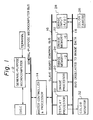
- Fig. 1 is a block diagram illustrating an example of an image processing apparatus having a bus dedicated to image data.
- the apparatus includes a general-purpose microcomputer 12 which functions as the overall host processor of the system, a plurality of slave boards for processing an image in hardware fashion, and a master controller & processor 14 for controlling the operation and function of the slave boards. More specifically, each board is operated by having its operating mode, function and parameters set by the master controller & processor 14 via a slave board control bus 16.
- the boards usually are interconnected via a six-to-nine channel bus 18 dedicated to image data, with an eight-bit bus serving as one channel.
- the data on the dedicated bus flows in the manner of a time series identical with that of a raster scan system in television, and one-sixtieth of a second is required to deliver all of the data in a single image frame.
- the bus dedicated to the image data employs horizontal and vertical synchronization as the timing base, and random accessing for a single image frame of data cannot be performed via the data bus 18.
- the dedicated bus uses vertical synchronization as a timing base, the processing performed by the boards connected thereto also has the vertical synchronization cycle (one-sixtieth of a second) as a single processing cycle.
- the setting of the operating mode, function and parameters of the slave boards by the master controller & processor ordinarily is carried out during the vertical blanking period.
- the master controller & processor not only controls the slave boards in accordance with an image processing request from the general-purpose microcomputer but also functions to compute such characterizing parameters as the cell edge trace, cell image area and perimeter of the cell images based on data obtained through processing performed by an image processor board 20. Furthermore, it is also possible for the master controller & processor to randomly access the contents of image memory boards 22, 24 via the slave board control bus, ascertain the position at which a cell appears, read the image data pertaining solely to this portion and compute other characterizing parameters.
- a planar sheath flow refers to a flow having a thickness the same as that of the thickest particle among the particles of interest and a width a number of times greater than that of the widest particle, e.g., a width which can be 100 times greater or more, wherein the flow is such that the particles of interest in the flow will not overlap one another in the direction of thickness.
- Examples of an apparatus in which a planar sheath flow is realized are disclosed in the specifications of Japanese Patent Publication No. 57-500995 and U.S.P.No. 4,338,024.
- strobe light or pulsed laser light having a short emission time is made to irradiate the flow from the thickness direction thereof, and an image is formed on the image pickup surface of a video camera (color camera) via an objective lens.
- the camera outputs analog signals resolved into the three colors R (red), G (green) and B (blue). These are fed into an image input board 28 which subjects them to an analog/digital (A/D) conversion.
- the resulting digital R, G and B data is stored in an image memory board 22 via a three-channel image data bus.
- the data is inputted also to the image processor board 20, which executes preprocessing for determining whether a cell is in view and for detecting the edge of the cell.
- Preprocessing entails extracting an average value of, e.g., G (green) and B (blue) data at each point (pixel) of an image and forming a histogram of the entire image frame in realtime.
- the data processed by the image processor board 20 is stored in the image memory board 24 via the dedicated bus 18.
- the image memory board 22 shall be used to store original image data and the image memory board 24 shall be employed to store data which has been processed.
- the master controller & processor 14 checks the histogram prepared in the image processor board 20 and determines whether a cell is present in a single imaged frame. If it is decided that no cell is present, then the program of the master controller & processor 14 returns to processing for the next imaged frame. When a cell is found to exist, the program proceeds to the next image processing step.
- An example of the next image processing step would be processing for subtracting previously stored background data from the imaged data, preparing a histogram from the results obtained, binarizing the image data as preprocessing for the purpose of tracing the edge of a cell, and detecting the cell edge. The resulting edge detection data is stored in the image memory board via the bus dedicated to image data.
- edge detection information might include eight-bit data made to correspond to each pixel of a single image frame, in which pixels that take on values other than 0 are regarded as cell edge points and the direction in which the next neighboring cell edge point is located is indicated by the particular value.
- the master controller and processor 14 refers to the edge detection information in the image memory board via the slave board control bus 16, and the edge of each and every cell is traced by means of a microprogram.
- computations for the area and perimeter of each cell, cumulative chromaticity information and shape parameters are performed. Each cell is then classified based on the characterizing parameters obtained.
- processing is necessary in which the position occupied by each cell in the frame is determined from the results of edge tracing for each cell, partial regions of the original frame in which cells are present are extracted, and the regions are gathered together in accordance with each cell class and saved in memory.
- the cell image data saved in accordance with each class is inputted to a display processor board 30 via the dedicated bus 18 and is displayed on a color monitor 32.
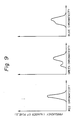
- a chromaticity histogram is a graph in which the chromaticity of each pixel of a cell interior is plotted along the horizontal axis and the number of pixels (frequency) having this chromaticity value is plotted along the vertical axis.
- Cumulative chromaticity information and the chromaticity histogram can be extremely important in cases where cells are capable of being dyed in different colors using certain suitable dyeing solutions in order to identify and classify the cells.
- the master controller & processor 14 Upon determining an area in which cell images are present by tracing the edges of the cells, the master controller & processor 14 accesses the image memory storing the original imaged frame via the slave board control bus 16, reads in the image data indicative of cell interior one or two pixels at a time, computes cumulative chromaticity information and prepares chromaticity histograms.
- the object of processing is not original image data but image gradient data computed in accordance with the Sobel formula for obtaining an image gradient, cumulative gradient information and gradient histograms representing cell interior complexity are obtained.
- This processing system is disadvantageous in that considerable time is needed for the master controller & processor to access the image memories.
- Several microseconds are required for one to two pixels of data to be processed in steps (1) through (3) described above. If the number of pixels in a cell image is 2000 and the processing of steps (1) through (3) requires 3 ⁇ s, by way of example, then 18 ms (milliseconds) will be needed in order to obtain three-color cumulative chromaticity information and chromaticity histograms of the cell image. This length of time is greater than a vertical synchronizing cycle of 16.7 ms. This means that realtime processing for an imaged picture that changes every one-sixtieth of a second is impossible.
- Another disadvantage of the foregoing system is that a greater load is placed upon the master controller & processor.
- the limitation on the processing capability of the master controller & processor limits the processing capability of the entire image processing system, so that the provision of the bus dedicated to image data loses its meaning.
- the advantage of the dedicated bus is to make possible greater diversification of processing, parallel processing and pipeline operation by allowing several processor boards and image memory boards to be connected to the bus when necessary, thereby making realtime processing feasible even with regard to an image that changes every one-sixtieth of a second.
- This method is implemented by providing a cumulative adder and a histogram forming circuit within the image processor boards connected to the bus dedicated to image data. Processing for obtaining cumulative chromaticity information and processing for obtaining chromaticity histograms will be described separately hereinbelow.
- the processing steps (1) through (3) are executed in parallel though there is a time lag involved, and processing for one imaged frame is completed in one-sixtieth of a second.
- processing for one imaged frame is completed in one-sixtieth of a second.
- the foregoing processing it is required that the foregoing processing be repeated three times, so that the length of time required is three times one-sixtieth of a second.
- step (5) The computation involved in step (5) will now be described.
- the foregoing computation is repeated three times in order to obtain cumulative chromaticity information for each of the three colors.
- This method of obtaining cumulative chromaticity information has a number of drawbacks.
- a window of this kind refers to a time region having horizontal and vertical synchronizing signals as the timing base.
- a window function is one in which, of the data on the dedicated bus, only data in the window period is taken as the object of processing. The processing steps involved in this method will be described with reference to Fig. 14.
- This method of obtaining cumulative chromaticity information also has a number of drawbacks.
- the image processor board is equipped with only one window function and only one histogram forming circuit, as mentioned above, three vertical synchronizing cycles will be needed to obtain a chromaticity histogram for each of the three colors. If two or more cells are present in a single imaged frame, a correspondingly greater amount of time is required and realtime processing of the imaged frame every one-sixtieth of a second becomes impossible.
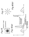
- the histogram prepared by the image processor board contains not only the cell image portion (the portion A in Fig. 16) but also the background portion around the cell image.
- the interior part of the cell has almost the same color as the cell background, in which case the histogram of the background portion (the portion B in Fig. 16) and the histogram of the cell portion (the portion A in Fig. 16) overlap each other, thereby making it difficult to obtain an accurate histogram of the cell portion alone.
- An object of the present invention is to solve the foregoing problems involved in the above-described conventional methods of obtaining the cell image parameters such as the cumulative chromaticity information, chromaticity histograms and cumulative gradients of each cell, thereby making it possible to realize, at low cost, realtime processing of an imaged frame that changes every one-sixtieth of a second, and to obtain accurate histograms solely of the cell image portions.
- the foregoing object is attained by providing a cell image processing method comprising the steps of capturing a cell image by image pickup means, storing the captured image data as an original image data, binarizing the image data upon identifying a background portion and cell image portions contained in the original image data, deriving cell edge detection information for each pixel from the binarized image data, tracing cell edges, in order to obtain edge points of the cells, by referring to the edge detection information, and deriving various cell image parameters by referring to results of edge tracing, characterized by deriving cell identification codes when the edge tracing is performed, the cell identification codes identifying each edge point to indicate which edge point belongs to which cell and indicating which side of the edge point is exterior to the cell, the aforementioned cell image parameters being derived by successively reading out the original image data and the cell identification codes upon correlating them with each pixel.
- the above-described method further includes a step of deriving a processed image data by subjecting the original image data to processing for making cell features more conspicuous, in which case the processed image data may be employed instead of the original image data as the image data which is the object of the above-described image processing.
- the step of deriving the cell image parameters includes the steps of adopting the original image data or the processed image data as the image data which is the object of image processing, and determining from the cell identification codes whether each pixel of the image data which is the object of image processing is an edge on a starting-point side of a cell as seen in a pixel-by-pixel scanning direction, latching a cell number read from the cell identification codes when it is determined that the pixel is an edge on the starting-point side, totalizing image data of each pixel cell number by cell number, determining from the identification codes whether each pixel of the image data which is the object of image processing is an edge on an end-point side of a cell as seen in a pixel-by-pixel scanning direction, unlatching the cell number when it is determined that the pixel is an edge on the end-point side, and determining whether processing of all pixels has ended.
- the foregoing object is attained by providing a cell image processing apparatus employing a method of capturing a cell image data by image pickup means, storing the captured image data as an original image data, adopting the original image data, or a processed image data obtained by subjecting the original image data to processing for making cell features more conspicuous, as an image data which is the object of image processing, binarizing the image data upon identifying a background portion and cell image portions contained in the original image data, deriving cell edge detection information for each pixel from the binarized image data, tracing cell edges, in order to obtain edge points of the cells, by referring to the edge detection information, and deriving various cell image parameters by referring to results of edge tracing, the apparatus comprising means for deriving cell identification codes identifying each of the edge points to indicate which edge point of the image data which is the object of image processing belongs to which cell and indicating which side of the edge point is exterior to the cell, means for successively reading out the image data which is the object of image processing
- a characterizing cell identification code is derived during edge tracing.
- the cell identification code identifies which edge point of the image data which is the object of processing belongs to which cell and indicates which side of the edge point is exterior to the cell.
- the cell identification code is used when deriving the cell image parameters. It is determined from the cell identification code whether each pixel of the image data which is the object of image processing is an edge on a starting-point side of a cell as seen in a pixel-by-pixel scanning direction. When it is determined that the pixel is an edge on the starting-point side, a cell number read from the cell identification code is latched, and the image data of each pixel is totalized cell number by cell number.
- each pixel of the image data which is the object of image processing is an edge on an end-point side of a cell as seen in a pixel-by-pixel scanning direction.
- the cell number is unlatched.
- the foregoing method makes it possible to obtain the cell image parameters by specifying a cell number for each cell.
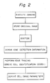
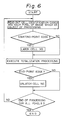
- Fig. 2 is a simple flowchart illustrating the overall flow of the cell image processing method of the invention.
- An image captured by the video camera (a color camera and image pick-up device) 26 is stored in the image memory board 22 as an original image.
- processing for binarizing the image is executed by the image processor board 20 in such a manner that background takes on a value of logical "0" while portions occupied by cell images take on a value of logical "1".
- the binarized data typically is gathered into a 3 x 3 pixel array of three pixels from left to right in the scanning direction land three pixels from top to bottom, this data is inputted to an edge detector within the board to compute edge detection information for each and every pixel, and the information is outputted to the image memory board 24.
- the image processor board 20 counts how many edge points there are on each horizontal line in one frame and is capable of storing this value in realtime.
- the edge count value is necessary when performing edge tracing if there are a large number of cells in a single picture. More specifically, whenever one point of an edge is traced in point-to-point edge tracing, the edge count value of the horizontal line corresponding to this edge is decremented. When tracing of the edge points of all cells in a single frame image is thus completed, all of the counted values become zero. If all of the counted values are not zero, this means that the edges of other cells are present.
- the master controller & processor 14 performs cell edge tracing, and prepares a chain code of the edge of each cell, while referring to the edge detection information stored in the image memory and the information indicative of the number of edge points per horizontal line stored in the image processor board.
- the chain code is a code well-known to those skilled in the art and it is from this code that the perimeter, area and shape parameter of each cell are obtained.
- a code peculiar to the invention namely a cell identification code
- the cell identification codes replace the edge detector information in the image memory.
- a cell identification code is shown in Fig. 3.
- a cell number which is for identifying a cell when a large number of cells are present in one imaged frame, is expressed by five bits b0 through b4, and whether an edge point of the cell is located on a starting-point side or end-point side of the cell as seen in the pixel-by-pixel image scanning direction is expressed by two bits b5 and b6.
- the pixel-by-pixel image scanning direction is from left to right in the horizontal direction.
- the pixel-by-pixel scan in image processing shall also be taken as being from left to right in the horizontal direction.
- a certain pixel is an edge on the starting-point side of a cell, this means that when processing (scanning) is performed one pixel at a time in the horizontal direction, the cell image portion starts from this pixel.
- the left side of an edge on the starting-point side is outside the cell.
- "1" is written in the bit b6 of the cell identification code with regard to a pixel which is an edge on the starting-point side.
- a certain pixel is an edge on the end-point side of a cell
- scanning is performed in the horizontal direction from the left side, the right side of an edge on the end-point side is outside the cell.
- "1" is written in the bit b5 of the cell identification code with regard to a pixel which is an edge on the end-point side.
- the code of two bits b5, b6 can readily be obtained from the edge detection information at the time of edge tracing. An example in which an edge point is so coded will be described hereinbelow.
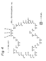
- edge detection information refers to a value decided in accordance with each pixel of an image. If a corresponding pixel is not an edge, the value assigned is "0"; if it is an edge, the assigned value is a non-zero value indicating in which direction the next neighboring edge is located when the periphery of the cell is traversed in the clockwise direction. Though there are various ways in which the values can be assigned, it will be assumed here that the values shown in Fig. 17 are assigned in order to facilitate the description.
- the starting point of tracing is a point C, namely the first point on the edge of a cell of interest hit when the image is scanned in a television scanning method. Since the next edge point neighboring the point C is on the right side, edge detection information "a" is assigned to the point C in accordance with the rule shown in Fig. 17.
- the edge detection information "a" at the point C is converted into a cell identification code in which the bit b5 is "0" and the bit b6 is "1". The reason for making this conversion is obvious in view of the aforementioned definition of the bits b5 and b6.
- the contents of the two bits b6, b5 are represented by (b6, b5). That is, the two-bit code of point C is (1, 0).
- the edge detection information for a point D which is the next edge point also takes on the value "a”. Therefore, b5 of the cell identification code for point D is "0", and b6 is "0" because the edge detection information for point C, which is the immediately preceding edge point, had the value "a”. Thus, the code of point D is expressed by (0, 0).
- the edge detection information for a point E which is the next edge point takes on a value "h”. Therefore, b5 of the cell identification code for point E is "1", and b6 is "0" because the edge detection information for point D, which is the immediately preceding edge point, had the value "a”. Thus, the code of point E is expressed by (0, 1).
- a cell identification code for each edge point can be obtained while edge tracing is performed based on the edge detection information.
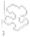
- Fig. 5 illustrates an example in which another cell image is subjected to edge tracing and cell identification codes are obtained in the same manner.
- the numerals 3 in Fig. 4 and the numerals 5 in Fig. 5 represent cell numbers. Naturally, the same cell number is assigned to each edge point of the same cell.
- edge detection information indicative of pixels other than those at edge points is "0". Therefore, even after the edge detection information in the image memory is replaced by the above-mentioned cell identification codes, pixels other than edge points remain unchanged, i.e., "0" [the code for these pixels being (0, 0)].
- the edge tracing which includes the above-described encoding processing is executed by a microprogram.
- the processing speed is about 10 ⁇ s per edge point, so that processing can be executed for about 1,500 edge points in 16.7 ms, which is the vertical synchronization cycle. Assuming that there are 150 edge points per cell, this means that up to ten cells can be edge traced in a single vertical synchronization cycle.
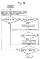
- Fig. 6 describes a procedure for obtaining cell image parameters such as cumulative chromaticity information and chromaticity histograms for each cell based on the information acquired by making the conversion from the edge detection information to the cell identification codes.
- This procedure is realized by providing an image processor board having the functions of a decoder for reading the cell identification codes, a memory, an adder and an incrementer, etc.
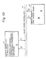
- Fig. 7 is a block diagram of a main part of this image processor board. The description that follows is based on this block diagram.
- the original image data and cell identification codes stored respectively in the image memory boards 22 and 24 of Fig. 1 are inputted to the image processor board 20 via the bus 18 dedicated to image data.
- the flow of these data on the bus 18 takes place at a timing the same as that of raster scanning in television. Data flow is in order from the data at the upper left end of the screen.
- the cell identification codes are inputted to a latch circuit 38 in the processor board 20 via a line 36.
- the image data for each pixel is inputted to a latch circuit 42 via a line 40.
- a pixel synchronizing clock which is one signal on the dedicated bus, is inputted to CLK terminals of the latch circuits 38, 42 via a line 44.
- the cell identification codes are latched in the latch circuit 38 synchronously with the pixel clock.
- the cell numbers expressed by the five bits of the cell identification codes are outputted from the latch circuit 38 to a line 46.
- the content of the bit b6, which is the bit in the cell identification codes that indicates whether a pixel presently being processed is an edge point on the left side (starting-point side) of a cell, is outputted from the latch circuit 38 to a line 48.
- a gate 50 takes the logical product of the signal on line 48 and the pixel synchronizing clock on line 44 and delivers the result to the CLK terminal of a latch circuit 52. If the bit b6 is "1", namely if the above-mentioned pixel is an edge point on the left side, the cell number on line 46 is latched in the latch circuit 52.
- This cell number is expressed by as numeral of from 1 to 31, the number 0 not being used.
- the latched cell number is supplied to the higher order address line of a histogram memory 54 and to an address line of a cumulative chromaticity memory 56 via a line 58.
- the image data is latched in the latch circuit 42 synchronously with the pixel clock, and this data is inputted via a line 62 to a lower order address line of the histogram memory 54 and an adder 60 for computing cumulative chromaticity.
- the histogram memory 54 which is provided with the cell number and pixel data as addresses, outputs a frequency value stored at a memory address corresponding to the value of the pixel data for the particular cell.
- the frequency value is outputted on a line 64. Though this value is initially "0", the value is incremented by an incrementer 66 whenever the pixel data of the cell is inputted to the histogram memory 54, and the result is written in the former same memory address to achieve updating.
- the cumulative chromaticity memory 56 which is provided with the cell number as an address, outputs a cumulative value of pixel data stored at a memory address corresponding to the particular cell. This cumulative value is outputted on a line 68. Though this value is initially "0", the value is added to the prevailing cumulative value by an adder 60 whenever pixel data of the cell arrives and the result is again stored in the memory address corresponding to the cell to achieve updating.
- the foregoing processing is executed with respect to all data in the period of time from the moment it is determined that the bit b6 of the cell identification code is "1" until a cell identification code in which the bit b5 is "1" arrives.
- the fact that the bit b5 is "1” means that the pixel corresponding to the cell identification code is an edge point, and that the right side of this edge is on the outside of the cell.
- bit b5 which is the bit in the cell identification codes that indicates whether a pixel presently being processed is an edge point on the right side (end-point side) of a cell
- bit b5 becomes "1”
- the signal on line 70 is inputted to the CLR terminal of the latch circuit 52 via the flip-flops 72, 74 and a gate 76.
- the latch circuit is cleared at this time and the cell number outputted on line 58 becomes 0. Since the arranged is such that the cell number 0 is not used for numbering a cell, as mentioned above, the cell number 0 represents a portion within the image that is outside the cell.
- the results of processing image data indicative of the portion outside a cell, namely background, are stored at memory addresses of the histogram memory 54 and cumulative chromaticity memory 56 that correspond to the cell number 0. Accordingly, regardless of whether image data is indicative of a cell portion or background, the incrementer 66 and adder 60 are capable of subjecting all image data to the same processing so that the control circuit for this processing is simply constructed.
- the two stages of flip-flops 72, 74 are for providing a delay in order to also subject the image data indicative of the right-side edge point of a cell to the foregoing processing as data indicative of the interior of the cell.
- Horizontal synchronizing pulses are inputted to the CLR terminal of the latch circuit 52 via line 78 and gate 76. Since the gate 76 takes the logical sum of these pulses and the Q output of the flip-flop 74, the latch circuit 52 is cleared when the bit b5 becomes "1" or when a horizontal synchronizing pulse is inputted thereto.
- the cell number is latched by a left-side edge point of one cell in the scanning direction.
- the incrementer 66 and adder 60 execute processing with this cell number kept as is until the right-side edge of the cell in the scanning direction is passed.
- the cell number is cleared to 0, followed by execution of the foregoing processing.
- the cell number of this cell is latched and processing similar to that described above is then carried out.
- scanning in the horizontal direction reaches the right edge of the image, the cell number is cleared to 0 by a horizontal synchronizing pulse and the next horizontal line is then scanned.
- the histogram memory 54 and cumulative chromaticity memory 56 are also connected to the slave board control bus 16 so that the contents of these memories can be accessed by the master controller & processor 14.
- processing such as for calculating the area of a cell by adding up the frequency values of the cell chromaticity histogram after the histogram is obtained can readily be performed by the master controller & processor.
- the cumulative chromaticity information and chromaticity histograms can be obtained as described above.
- image gradient data is used as the image data, then cumulative gradient information and a gradient histogram can be obtained. It is also possible to use image data, which is of a type different from that mentioned above, obtained by making a conversion into data which makes cell features more conspicuous.
- the cell identification code is one in which a cell number and edge information are written in one word of eight bits, as shown in Fig. 3.
- the cell identification code is divided into two or more words in each of which a cell number or image information may be written. It is also possible to increase the cell number to more than five bits so that more cells can be processed at one time.
Landscapes
- Engineering & Computer Science (AREA)
- Physics & Mathematics (AREA)
- Life Sciences & Earth Sciences (AREA)
- Biomedical Technology (AREA)
- General Health & Medical Sciences (AREA)
- Molecular Biology (AREA)
- Health & Medical Sciences (AREA)
- General Physics & Mathematics (AREA)
- Multimedia (AREA)
- Theoretical Computer Science (AREA)
- Image Analysis (AREA)
- Investigating Or Analysing Biological Materials (AREA)
- Image Processing (AREA)
- Processing Or Creating Images (AREA)
Applications Claiming Priority (2)
| Application Number | Priority Date | Filing Date | Title |
|---|---|---|---|
| JP63070775A JP2686274B2 (ja) | 1988-03-24 | 1988-03-24 | 細胞画像処理方法および装置 |
| JP70775/88 | 1988-03-24 |
Publications (3)
| Publication Number | Publication Date |
|---|---|
| EP0333921A2 true EP0333921A2 (de) | 1989-09-27 |
| EP0333921A3 EP0333921A3 (de) | 1991-10-02 |
| EP0333921B1 EP0333921B1 (de) | 1996-02-07 |
Family
ID=13441234
Family Applications (1)
| Application Number | Title | Priority Date | Filing Date |
|---|---|---|---|
| EP88119873A Expired - Lifetime EP0333921B1 (de) | 1988-03-24 | 1988-11-29 | Anlage und Verfahren zur Zellbildverarbeitung |
Country Status (4)
| Country | Link |
|---|---|
| US (1) | US5099521A (de) |
| EP (1) | EP0333921B1 (de) |
| JP (1) | JP2686274B2 (de) |
| DE (1) | DE3854996T2 (de) |
Cited By (4)
| Publication number | Priority date | Publication date | Assignee | Title |
|---|---|---|---|---|
| DE19726226A1 (de) * | 1997-06-22 | 1998-12-24 | Zentrum Fuer Neuroinformatik G | Verfahren zum automatisierten Erkennen von Strukturen in Schnitten durch biologische Zellen oder biologisches Gewebe |
| EP1565873A4 (de) * | 2002-11-18 | 2011-04-13 | Internat Remote Imaging Systems Inc | Teilchenextraktion f r ein automatischesstr mungsmikroskop |
| US20140153812A1 (en) * | 2012-11-30 | 2014-06-05 | Dainippon Screen Mfg. Co., Ltd. | Apparatus for and method of processing image and storage medium |
| CN105067617A (zh) * | 2015-07-21 | 2015-11-18 | 上海理工大学 | 一种基于相衬图像和共焦散射显微光谱细胞识别装置及方法 |
Families Citing this family (41)
| Publication number | Priority date | Publication date | Assignee | Title |
|---|---|---|---|---|
| US5121436A (en) * | 1987-08-14 | 1992-06-09 | International Remote Imaging Systems, Inc. | Method and apparatus for generating a plurality of parameters of an object in a field of view |
| US5224175A (en) * | 1987-12-07 | 1993-06-29 | Gdp Technologies, Inc. | Method for analyzing a body tissue ultrasound image |
| JP3111706B2 (ja) * | 1992-02-18 | 2000-11-27 | 株式会社日立製作所 | 粒子分析装置及び粒子分析方法 |
| US5889881A (en) * | 1992-10-14 | 1999-03-30 | Oncometrics Imaging Corp. | Method and apparatus for automatically detecting malignancy-associated changes |
| US6026174A (en) * | 1992-10-14 | 2000-02-15 | Accumed International, Inc. | System and method for automatically detecting malignant cells and cells having malignancy-associated changes |
| EP0610916A3 (de) * | 1993-02-09 | 1994-10-12 | Cedars Sinai Medical Center | Verfahren und Vorrichtung zur Erzeugung vorzugsweiser segmentierter numerischer Bilder. |
| DE69435214D1 (de) * | 1993-12-10 | 2009-08-06 | Ricoh Kk | Verfahren zur Bilderkennung und zum Herausziehen und Erkennen eines spezifizierten Bildes aus einem Bildeingabesignal |
| US5550933A (en) * | 1994-05-27 | 1996-08-27 | Duke University | Quadrature shape detection using the flow integration transform |
| JP3415270B2 (ja) * | 1994-06-03 | 2003-06-09 | ソニー株式会社 | 画像信号符号化方法及び復号方法 |
| US5848177A (en) * | 1994-12-29 | 1998-12-08 | Board Of Trustees Operating Michigan State University | Method and system for detection of biological materials using fractal dimensions |
| US5741213A (en) * | 1995-10-25 | 1998-04-21 | Toa Medical Electronics Co., Ltd. | Apparatus for analyzing blood |
| US6272235B1 (en) * | 1997-03-03 | 2001-08-07 | Bacus Research Laboratories, Inc. | Method and apparatus for creating a virtual microscope slide |
| US6396941B1 (en) * | 1996-08-23 | 2002-05-28 | Bacus Research Laboratories, Inc. | Method and apparatus for internet, intranet, and local viewing of virtual microscope slides |
| US6404906B2 (en) | 1997-03-03 | 2002-06-11 | Bacus Research Laboratories,Inc. | Method and apparatus for acquiring and reconstructing magnified specimen images from a computer-controlled microscope |
| US6031930A (en) * | 1996-08-23 | 2000-02-29 | Bacus Research Laboratories, Inc. | Method and apparatus for testing a progression of neoplasia including cancer chemoprevention testing |
| US5969317A (en) * | 1996-11-13 | 1999-10-19 | Ncr Corporation | Price determination system and method using digitized gray-scale image recognition and price-lookup files |
| US20030036855A1 (en) * | 1998-03-16 | 2003-02-20 | Praelux Incorporated, A Corporation Of New Jersey | Method and apparatus for screening chemical compounds |
| US6388788B1 (en) | 1998-03-16 | 2002-05-14 | Praelux, Inc. | Method and apparatus for screening chemical compounds |
| US6879719B1 (en) * | 2000-02-24 | 2005-04-12 | International Business Machines Corporation | Method for measurement of full-two dimensional submicron shapes |
| US6466690C1 (en) * | 2000-12-19 | 2008-11-18 | Bacus Res Lab Inc | Method and apparatus for processing an image of a tissue sample microarray |
| US7155049B2 (en) * | 2001-01-11 | 2006-12-26 | Trestle Acquisition Corp. | System for creating microscopic digital montage images |
| US6816606B2 (en) | 2001-02-21 | 2004-11-09 | Interscope Technologies, Inc. | Method for maintaining high-quality focus during high-throughput, microscopic digital montage imaging |
| US6993169B2 (en) * | 2001-01-11 | 2006-01-31 | Trestle Corporation | System and method for finding regions of interest for microscopic digital montage imaging |
| US6798571B2 (en) | 2001-01-11 | 2004-09-28 | Interscope Technologies, Inc. | System for microscopic digital montage imaging using a pulse light illumination system |
| GB0218909D0 (en) * | 2002-08-15 | 2002-09-25 | Qinetiq Ltd | Histological assessment |
| AU2003217694A1 (en) * | 2002-02-22 | 2003-09-09 | Bacus Research Laboratories, Inc. | Focusable virtual microscopy apparatus and method |
| US20040102903A1 (en) * | 2002-11-27 | 2004-05-27 | Graessle Josef A. | Biological growth plate scanner |
| US7351574B2 (en) * | 2002-11-27 | 2008-04-01 | 3M Innovative Properties Company | Loading and ejection systems for biological growth plate scanner |
| US20040101954A1 (en) * | 2002-11-27 | 2004-05-27 | Graessle Josef A. | Back side plate illumination for biological growth plate scanner |
| US20040202357A1 (en) | 2003-04-11 | 2004-10-14 | Perz Cynthia B. | Silhouette image acquisition |
| US7298886B2 (en) * | 2003-09-05 | 2007-11-20 | 3M Innovative Properties Company | Counting biological agents on biological growth plates |
| US7792338B2 (en) * | 2004-08-16 | 2010-09-07 | Olympus America Inc. | Method and apparatus of mechanical stage positioning in virtual microscopy image capture |
| JP5055293B2 (ja) * | 2005-12-07 | 2012-10-24 | ザ ジェイ. デヴィッド グラッドストーン インスティテューツ | ミトコンドリア機能を調節する物質を同定する方法 |
| WO2009111301A1 (en) * | 2008-03-04 | 2009-09-11 | 3M Innovative Properties Company | Information management in automated processing of biological growth media |
| JP5306382B2 (ja) * | 2008-03-04 | 2013-10-02 | スリーエム イノベイティブ プロパティズ カンパニー | 測定された製造特性に基づく生物学的増殖培地の処理 |
| US8693743B1 (en) | 2010-02-19 | 2014-04-08 | Olive Tree Media, LLC | Analysis and display of multiple biomarker co-expression in cells and tissues |
| US8767069B2 (en) * | 2010-06-30 | 2014-07-01 | Luminex Corporation | Apparatus, system, and method for increasing measurement accuracy in a particle imaging device using light distribution |
| WO2017032621A1 (en) | 2015-08-24 | 2017-03-02 | Koninklijke Philips N.V. | Server-client architecture in digital pathology |
| KR102822445B1 (ko) | 2019-12-31 | 2025-06-19 | 엘지디스플레이 주식회사 | 유기전기소자, 이를 포함하는 표시패널 및 이를 포함하는 표시장치 |
| WO2024162311A1 (ja) | 2023-01-31 | 2024-08-08 | パナソニックIpマネジメント株式会社 | リチウム一次電池 |
| CN115908429B (zh) * | 2023-03-08 | 2023-05-19 | 山东歆悦药业有限公司 | 一种泡脚药粉研磨精度检测方法及系统 |
Family Cites Families (4)
| Publication number | Priority date | Publication date | Assignee | Title |
|---|---|---|---|---|
| US3408485A (en) * | 1965-02-24 | 1968-10-29 | Perkin Elmer Corp | Apparatus for counting irregularly shaped objects |
| US3851156A (en) * | 1972-09-05 | 1974-11-26 | Green James E | Analysis method and apparatus utilizing color algebra and image processing techniques |
| US4453266A (en) * | 1980-04-21 | 1984-06-05 | Rush-Presbyterian-St. Luke's Medical Center | Method and apparatus for measuring mean cell volume of red blood cells |
| US4566126A (en) * | 1982-04-30 | 1986-01-21 | Fuji Electric Company, Ltd. | Pattern discriminator |
-
1988
- 1988-03-24 JP JP63070775A patent/JP2686274B2/ja not_active Expired - Fee Related
- 1988-11-21 US US07/273,897 patent/US5099521A/en not_active Expired - Lifetime
- 1988-11-29 DE DE3854996T patent/DE3854996T2/de not_active Expired - Fee Related
- 1988-11-29 EP EP88119873A patent/EP0333921B1/de not_active Expired - Lifetime
Cited By (6)
| Publication number | Priority date | Publication date | Assignee | Title |
|---|---|---|---|---|
| DE19726226A1 (de) * | 1997-06-22 | 1998-12-24 | Zentrum Fuer Neuroinformatik G | Verfahren zum automatisierten Erkennen von Strukturen in Schnitten durch biologische Zellen oder biologisches Gewebe |
| DE19726226C2 (de) * | 1997-06-22 | 2001-07-26 | Zentrum Fuer Neuroinformatik G | Verfahren zum automatisierten Erkennen von Strukturen in Schnitten durch biologische Zellen oder biologisches Gewebe |
| EP1565873A4 (de) * | 2002-11-18 | 2011-04-13 | Internat Remote Imaging Systems Inc | Teilchenextraktion f r ein automatischesstr mungsmikroskop |
| US20140153812A1 (en) * | 2012-11-30 | 2014-06-05 | Dainippon Screen Mfg. Co., Ltd. | Apparatus for and method of processing image and storage medium |
| US9639736B2 (en) * | 2012-11-30 | 2017-05-02 | SCREEN Holdings Co., Ltd. | Apparatus for and method of processing image and storage medium |
| CN105067617A (zh) * | 2015-07-21 | 2015-11-18 | 上海理工大学 | 一种基于相衬图像和共焦散射显微光谱细胞识别装置及方法 |
Also Published As
| Publication number | Publication date |
|---|---|
| DE3854996T2 (de) | 1996-10-24 |
| US5099521A (en) | 1992-03-24 |
| JPH01242961A (ja) | 1989-09-27 |
| JP2686274B2 (ja) | 1997-12-08 |
| EP0333921B1 (de) | 1996-02-07 |
| EP0333921A3 (de) | 1991-10-02 |
| DE3854996D1 (de) | 1996-03-21 |
Similar Documents
| Publication | Publication Date | Title |
|---|---|---|
| EP0333921B1 (de) | Anlage und Verfahren zur Zellbildverarbeitung | |
| US4162482A (en) | Pre-processing and feature extraction system for character recognition | |
| US5796868A (en) | Object edge point filtering system for machine vision | |
| US5136658A (en) | Number plate image detecting apparatus | |
| KR920005868B1 (ko) | 화상처리장치 | |
| US5157740A (en) | Method for background suppression in an image data processing system | |
| EP2650824B1 (de) | Bildverarbeitungsvorrichtung und Bildverarbeitungsverfahren | |
| US4545070A (en) | Pattern discriminator | |
| JP3853034B2 (ja) | 物体の境界決定方法および装置並びに物体の境界決定プログラムを記録した記録媒体 | |
| US5068906A (en) | Processor for extracting and memorizing cell images | |
| EP0669593A2 (de) | Erkennungsverfahren für eine zweidimensionale Kodierung | |
| CN116249015B (zh) | 摄像头遮挡检测方法、装置、摄像头设备及存储介质 | |
| JPH0436433B2 (de) | ||
| US4887303A (en) | Character reading method | |
| JPS63205783A (ja) | 画調識別装置 | |
| CN117789182B (zh) | 工业仪表数据采集方法及系统 | |
| JP3358133B2 (ja) | 画像処理装置 | |
| CN120726576B (zh) | 一种智能安防的异常识别方法及装置 | |
| JP4299908B2 (ja) | 物体の境界決定方法および装置 | |
| JPH0744682A (ja) | 画像読取装置 | |
| JPH10240856A (ja) | コードリーダ | |
| JP3876584B2 (ja) | 画像検出装置及び画像検出方法 | |
| CN119785954A (zh) | 试纸卡判读方法及试纸卡判读装置 | |
| JPH0129643Y2 (de) | ||
| JP2843185B2 (ja) | しきい値決定方法及びその装置 |
Legal Events
| Date | Code | Title | Description |
|---|---|---|---|
| PUAI | Public reference made under article 153(3) epc to a published international application that has entered the european phase |
Free format text: ORIGINAL CODE: 0009012 |
|
| AK | Designated contracting states |
Kind code of ref document: A2 Designated state(s): DE FR GB IT |
|
| PUAL | Search report despatched |
Free format text: ORIGINAL CODE: 0009013 |
|
| AK | Designated contracting states |
Kind code of ref document: A3 Designated state(s): DE FR GB IT |
|
| 17P | Request for examination filed |
Effective date: 19920317 |
|
| 17Q | First examination report despatched |
Effective date: 19931103 |
|
| GRAA | (expected) grant |
Free format text: ORIGINAL CODE: 0009210 |
|
| ITF | It: translation for a ep patent filed | ||
| AK | Designated contracting states |
Kind code of ref document: B1 Designated state(s): DE FR GB IT |
|
| REF | Corresponds to: |
Ref document number: 3854996 Country of ref document: DE Date of ref document: 19960321 |
|
| ET | Fr: translation filed | ||
| PLBE | No opposition filed within time limit |
Free format text: ORIGINAL CODE: 0009261 |
|
| STAA | Information on the status of an ep patent application or granted ep patent |
Free format text: STATUS: NO OPPOSITION FILED WITHIN TIME LIMIT |
|
| 26N | No opposition filed | ||
| PGFP | Annual fee paid to national office [announced via postgrant information from national office to epo] |
Ref country code: FR Payment date: 19981110 Year of fee payment: 11 |
|
| PGFP | Annual fee paid to national office [announced via postgrant information from national office to epo] |
Ref country code: GB Payment date: 19981204 Year of fee payment: 11 |
|
| PGFP | Annual fee paid to national office [announced via postgrant information from national office to epo] |
Ref country code: DE Payment date: 19981207 Year of fee payment: 11 |
|
| PG25 | Lapsed in a contracting state [announced via postgrant information from national office to epo] |
Ref country code: GB Free format text: LAPSE BECAUSE OF NON-PAYMENT OF DUE FEES Effective date: 19991129 |
|
| GBPC | Gb: european patent ceased through non-payment of renewal fee |
Effective date: 19991129 |
|
| PG25 | Lapsed in a contracting state [announced via postgrant information from national office to epo] |
Ref country code: FR Free format text: LAPSE BECAUSE OF NON-PAYMENT OF DUE FEES Effective date: 20000731 |
|
| PG25 | Lapsed in a contracting state [announced via postgrant information from national office to epo] |
Ref country code: DE Free format text: LAPSE BECAUSE OF NON-PAYMENT OF DUE FEES Effective date: 20000901 |
|
| REG | Reference to a national code |
Ref country code: FR Ref legal event code: ST |
|
| PG25 | Lapsed in a contracting state [announced via postgrant information from national office to epo] |
Ref country code: IT Free format text: LAPSE BECAUSE OF NON-PAYMENT OF DUE FEES;WARNING: LAPSES OF ITALIAN PATENTS WITH EFFECTIVE DATE BEFORE 2007 MAY HAVE OCCURRED AT ANY TIME BEFORE 2007. THE CORRECT EFFECTIVE DATE MAY BE DIFFERENT FROM THE ONE RECORDED. Effective date: 20051129 |