EP0333959B1 - Erhitzer - Google Patents
Erhitzer Download PDFInfo
- Publication number
- EP0333959B1 EP0333959B1 EP88400692A EP88400692A EP0333959B1 EP 0333959 B1 EP0333959 B1 EP 0333959B1 EP 88400692 A EP88400692 A EP 88400692A EP 88400692 A EP88400692 A EP 88400692A EP 0333959 B1 EP0333959 B1 EP 0333959B1
- Authority
- EP
- European Patent Office
- Prior art keywords
- section
- air
- heat exchange
- combustion
- heater
- Prior art date
- Legal status (The legal status is an assumption and is not a legal conclusion. Google has not performed a legal analysis and makes no representation as to the accuracy of the status listed.)
- Expired
Links
- 238000002485 combustion reaction Methods 0.000 claims description 57
- 238000009423 ventilation Methods 0.000 claims description 39
- 239000011358 absorbing material Substances 0.000 claims description 2
- 238000010438 heat treatment Methods 0.000 claims description 2
- 239000007789 gas Substances 0.000 description 22
- 239000000203 mixture Substances 0.000 description 9
- 229910010293 ceramic material Inorganic materials 0.000 description 8
- 238000004891 communication Methods 0.000 description 5
- 238000010276 construction Methods 0.000 description 5
- 239000000463 material Substances 0.000 description 5
- 230000002093 peripheral effect Effects 0.000 description 5
- 238000012546 transfer Methods 0.000 description 3
- 239000000567 combustion gas Substances 0.000 description 2
- 238000009833 condensation Methods 0.000 description 2
- 230000005494 condensation Effects 0.000 description 2
- 238000007599 discharging Methods 0.000 description 2
- 230000000694 effects Effects 0.000 description 2
- 239000000446 fuel Substances 0.000 description 2
- 238000005192 partition Methods 0.000 description 2
- 238000007789 sealing Methods 0.000 description 2
- 239000004809 Teflon Substances 0.000 description 1
- 229920006362 Teflon® Polymers 0.000 description 1
- 230000002159 abnormal effect Effects 0.000 description 1
- 229910052782 aluminium Inorganic materials 0.000 description 1
- XAGFODPZIPBFFR-UHFFFAOYSA-N aluminium Chemical compound [Al] XAGFODPZIPBFFR-UHFFFAOYSA-N 0.000 description 1
- 239000010425 asbestos Substances 0.000 description 1
- 239000003054 catalyst Substances 0.000 description 1
- 239000000919 ceramic Substances 0.000 description 1
- 239000011248 coating agent Substances 0.000 description 1
- 238000000576 coating method Methods 0.000 description 1
- 230000007797 corrosion Effects 0.000 description 1
- 238000005260 corrosion Methods 0.000 description 1
- 238000001514 detection method Methods 0.000 description 1
- 238000001035 drying Methods 0.000 description 1
- 238000002474 experimental method Methods 0.000 description 1
- 239000003350 kerosene Substances 0.000 description 1
- 230000007257 malfunction Effects 0.000 description 1
- 238000004519 manufacturing process Methods 0.000 description 1
- 229910052751 metal Inorganic materials 0.000 description 1
- 239000002184 metal Substances 0.000 description 1
- 238000000034 method Methods 0.000 description 1
- 238000012856 packing Methods 0.000 description 1
- 229910052895 riebeckite Inorganic materials 0.000 description 1
- 238000004804 winding Methods 0.000 description 1
Images


Classifications
-
- F—MECHANICAL ENGINEERING; LIGHTING; HEATING; WEAPONS; BLASTING
- F24—HEATING; RANGES; VENTILATING
- F24F—AIR-CONDITIONING; AIR-HUMIDIFICATION; VENTILATION; USE OF AIR CURRENTS FOR SCREENING
- F24F3/00—Air-conditioning systems in which conditioned primary air is supplied from one or more central stations to distributing units in the rooms or spaces where it may receive secondary treatment; Apparatus specially designed for such systems
- F24F3/12—Air-conditioning systems in which conditioned primary air is supplied from one or more central stations to distributing units in the rooms or spaces where it may receive secondary treatment; Apparatus specially designed for such systems characterised by the treatment of the air otherwise than by heating and cooling
- F24F3/14—Air-conditioning systems in which conditioned primary air is supplied from one or more central stations to distributing units in the rooms or spaces where it may receive secondary treatment; Apparatus specially designed for such systems characterised by the treatment of the air otherwise than by heating and cooling by humidification; by dehumidification
- F24F3/1411—Air-conditioning systems in which conditioned primary air is supplied from one or more central stations to distributing units in the rooms or spaces where it may receive secondary treatment; Apparatus specially designed for such systems characterised by the treatment of the air otherwise than by heating and cooling by humidification; by dehumidification by absorbing or adsorbing water, e.g. using an hygroscopic desiccant
- F24F3/1423—Air-conditioning systems in which conditioned primary air is supplied from one or more central stations to distributing units in the rooms or spaces where it may receive secondary treatment; Apparatus specially designed for such systems characterised by the treatment of the air otherwise than by heating and cooling by humidification; by dehumidification by absorbing or adsorbing water, e.g. using an hygroscopic desiccant with a moving bed of solid desiccants, e.g. a rotary wheel supporting solid desiccants
-
- F—MECHANICAL ENGINEERING; LIGHTING; HEATING; WEAPONS; BLASTING
- F24—HEATING; RANGES; VENTILATING
- F24H—FLUID HEATERS, e.g. WATER OR AIR HEATERS, HAVING HEAT-GENERATING MEANS, e.g. HEAT PUMPS, IN GENERAL
- F24H3/00—Air heaters
- F24H3/02—Air heaters with forced circulation
- F24H3/06—Air heaters with forced circulation the air being kept separate from the heating medium, e.g. using forced circulation of air over radiators
- F24H3/065—Air heaters with forced circulation the air being kept separate from the heating medium, e.g. using forced circulation of air over radiators using fluid fuel
-
- F—MECHANICAL ENGINEERING; LIGHTING; HEATING; WEAPONS; BLASTING
- F28—HEAT EXCHANGE IN GENERAL
- F28D—HEAT-EXCHANGE APPARATUS, NOT PROVIDED FOR IN ANOTHER SUBCLASS, IN WHICH THE HEAT-EXCHANGE MEDIA DO NOT COME INTO DIRECT CONTACT
- F28D19/00—Regenerative heat-exchange apparatus in which the intermediate heat-transfer medium or body is moved successively into contact with each heat-exchange medium
- F28D19/04—Regenerative heat-exchange apparatus in which the intermediate heat-transfer medium or body is moved successively into contact with each heat-exchange medium using rigid bodies, e.g. mounted on a movable carrier
- F28D19/041—Regenerative heat-exchange apparatus in which the intermediate heat-transfer medium or body is moved successively into contact with each heat-exchange medium using rigid bodies, e.g. mounted on a movable carrier with axial flow through the intermediate heat-transfer medium
-
- F—MECHANICAL ENGINEERING; LIGHTING; HEATING; WEAPONS; BLASTING
- F24—HEATING; RANGES; VENTILATING
- F24F—AIR-CONDITIONING; AIR-HUMIDIFICATION; VENTILATION; USE OF AIR CURRENTS FOR SCREENING
- F24F2203/00—Devices or apparatus used for air treatment
- F24F2203/10—Rotary wheel
- F24F2203/1004—Bearings or driving means
-
- F—MECHANICAL ENGINEERING; LIGHTING; HEATING; WEAPONS; BLASTING
- F24—HEATING; RANGES; VENTILATING
- F24F—AIR-CONDITIONING; AIR-HUMIDIFICATION; VENTILATION; USE OF AIR CURRENTS FOR SCREENING
- F24F2203/00—Devices or apparatus used for air treatment
- F24F2203/10—Rotary wheel
- F24F2203/1012—Details of the casing or cover
-
- F—MECHANICAL ENGINEERING; LIGHTING; HEATING; WEAPONS; BLASTING
- F24—HEATING; RANGES; VENTILATING
- F24F—AIR-CONDITIONING; AIR-HUMIDIFICATION; VENTILATION; USE OF AIR CURRENTS FOR SCREENING
- F24F2203/00—Devices or apparatus used for air treatment
- F24F2203/10—Rotary wheel
- F24F2203/1032—Desiccant wheel
-
- F—MECHANICAL ENGINEERING; LIGHTING; HEATING; WEAPONS; BLASTING
- F24—HEATING; RANGES; VENTILATING
- F24F—AIR-CONDITIONING; AIR-HUMIDIFICATION; VENTILATION; USE OF AIR CURRENTS FOR SCREENING
- F24F2203/00—Devices or apparatus used for air treatment
- F24F2203/10—Rotary wheel
- F24F2203/104—Heat exchanger wheel
-
- F—MECHANICAL ENGINEERING; LIGHTING; HEATING; WEAPONS; BLASTING
- F24—HEATING; RANGES; VENTILATING
- F24F—AIR-CONDITIONING; AIR-HUMIDIFICATION; VENTILATION; USE OF AIR CURRENTS FOR SCREENING
- F24F2203/00—Devices or apparatus used for air treatment
- F24F2203/10—Rotary wheel
- F24F2203/1048—Geometric details
-
- F—MECHANICAL ENGINEERING; LIGHTING; HEATING; WEAPONS; BLASTING
- F24—HEATING; RANGES; VENTILATING
- F24F—AIR-CONDITIONING; AIR-HUMIDIFICATION; VENTILATION; USE OF AIR CURRENTS FOR SCREENING
- F24F2203/00—Devices or apparatus used for air treatment
- F24F2203/10—Rotary wheel
- F24F2203/1056—Rotary wheel comprising a reheater
- F24F2203/1064—Gas fired reheater
-
- F—MECHANICAL ENGINEERING; LIGHTING; HEATING; WEAPONS; BLASTING
- F24—HEATING; RANGES; VENTILATING
- F24F—AIR-CONDITIONING; AIR-HUMIDIFICATION; VENTILATION; USE OF AIR CURRENTS FOR SCREENING
- F24F2203/00—Devices or apparatus used for air treatment
- F24F2203/10—Rotary wheel
- F24F2203/1068—Rotary wheel comprising one rotor
-
- F—MECHANICAL ENGINEERING; LIGHTING; HEATING; WEAPONS; BLASTING
- F24—HEATING; RANGES; VENTILATING
- F24F—AIR-CONDITIONING; AIR-HUMIDIFICATION; VENTILATION; USE OF AIR CURRENTS FOR SCREENING
- F24F2203/00—Devices or apparatus used for air treatment
- F24F2203/10—Rotary wheel
- F24F2203/1084—Rotary wheel comprising two flow rotor segments
Definitions
- the present invention relates to a heater, more specifically, to a heater which is capable of exchanging heat between air sucked from the interior of a room and combustion heat generated during the combustion of a fuel such as gas or kerosene, with a very high level of efficiency.
- An FF type warm air heater is conventionally known.
- a known warm air heater of this type has a construction which can be outlined as follows: the heater is adapted to burn a fuel with air sucked from the exterior of the room and discharge air to the exterior of the room after the air has been used in the combustion; the heater is also adapted to perform heat exchange between air at a high temperature resulting from the combustion and air sucked from the interior of the room until the air at the high temperature is discharged to the exterior of the room, and forcibly supply the interior of the room with the air which has been subjected to heat exchange and thus had its temperature raised.
- Such a conventional heater mainly comprises a combustion section, a ventilation section, a heat exchange section between the combustion and ventilation sections, and a frame body which accommodates these members.
- the combustion section has a combustion chamber, a suction port for supplying fresh air from the exterior of the room to the inside of the combustion chamber by a suction fan, and an exhaust port communicating with the exterior of the room for discharging the air which has been used in the combustion to the exterior of the room.
- the heat exchange section is positioned between the combustion chamber and the exhaust port.
- the ventilation section has a suction port disposed on one side of the frame body for sucking air from the interior of the room, a discharge port disposed on the other side of the frame body for discharging air to the interior of the room, and a ventilation fan disposed between the suction and discharge ports, so that the sucked air is forcibly subjected to heat exchange.
- the heat exchange section is disposed between the combustion chamber and the exhaust port for providing heat exchange with air sucked from the interior of the room by the ventilation section. Air at high temperature resulting from the combustion passes through the heat exchange section, and, during the passage of the air, its temperature is reduced by a level corresponding to the energy used to raise the temperature of the air sucked from the interior of the room. Thereafter, the air which has had its temperature reduced is discharged to the exterior of the room.
- the conventionally known heater has the advantage that it enables the room to be heated without causing any reduction in the freshness of the air within the room.
- the conventional heater however, has the following disadvantages:
- the efficiency of the heat exchange in the heat exchange section between air at high a temperature provided by the combustion gases and air at a low temperature sucked from the interior of the room can be increased by increasing the heat transfer area of the heat exchanger.
- This increase in the transfer area causes an increase in the resistance to the flow of air in the flow passages caused by the ventilation fan.
- the conventional heater Since the conventional heater is adapted to discharge all the air which has been used in the combustion, the moisture in that air is also discharged after it has been vaporized during the combustion. This arrangement, therefore, abnormally dries the interior of the room as it is heated by the heater.
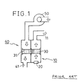
- the heater which has a construction as shown in fig 1 (PRIOR ART) is also disclosed in FR-A-2 117 406.
- the heater is provided with air flow routes which are: a combustion route extending from a gas burner unit 20 disposed in a combustion section 10 of the heater to an exhaust port 11 through a rotary body 30; and a heating route extending from a heat exchange fan 50 serving as a ventilation section 40 of the heater to a discharge port 41 through the rotary body 30.
- the rotary body 30 is positioned across these combustion and ventilation sections 10 and 40 so as to rotate at that position.
- the rotary body 30 has air flow passages 31 which extends in the same direction as the axis of rotation thereof.
- the rotary body 30 provided with the flow passages 31 is used as a heat exchange section. Therefore, air at a high temperature resulting from combustion by the gas burner unit 20 is allowed to pass through the flow passages 31 before the air arrives at the exhaust port 11. When the high-temperature air is passing through the flow passages 31, the air heats the rotary body 30.
- the rotary body 30 is adapted to rotate continuously. Therefore, while the body 30 rotates, part of the body 30 which has been heated in the combustion section 10 is moved to the other side of the heater where the ventilation section 40 is located.
- the part of the rotary body 30 which has thus been heated and moved to the ventilation section 40 side then exchanges heat with air which is being forced to circulate through the interior of the room and the heater by the ventilation section 40, whereby the air is heated while that part of the rotary body 30 is cooled.
- Moisture is generated by the combustion in the combustion section 10. Part of the moisture is discharged to the discharge port 11 through the flow passages 31 of the rotary body 30, while the retraining moisture attaches to the passages 31 of the rotary body 30.
- the part of the moisture generated by the combustion in the combustion section 10 that has attached to the flow passages 31 of the rotary body 30 is allowed to join an air flow from the heat exchange fan 50 when the part of the rotary body 30 that carries the moisture has been moved to the ventilation section 40 side by the rotation of the rotary body 30, and the moisture is then discharged from the discharge port 41.
- the heater according to Fig. 1 (prior art) is capable of moistening air to be supplied to the room, using moisture generated by the combustion, while the heater heats the air.
- An object of the present invention is to provide a heater which is provided with a rotary body positioned across combustion and ventilation sections of the heater so as to rotate at that position, and with air passages formed in the rotary body for effecting heat exchange, and which is capable of performing heat exchange with an increased efficiency and is also capable of supplying vapor generated during combustion to the interior of the room to thereby prevent the interior of the room from being abnormally dried.
- the rotary body having air flow passages is positioned across the combustion and ventilation sections so as to rotate at that position.
- the part of the rotary body that is positioned on the side of the heater where the combustion section is located has its temperature raised by heat generated by combustion while the heat is passing through the flow passage.
- the heat exchange section is able to effect continuous heat exchange, thereby enabling a highly efficient heat exchange.
- the internal pressure on the ventilation section side of the rotary member is higher than that on the combustion section side thereof, it is possible to prevent air from flowing from the combustion section side to the ventilation section side, thereby preventing the air used in combustion from flowing through the ventilation section. This effect is provided even if the heater is adapted to discharge air used in combustion to the outside in order to prevent any reduction in freshness of air within the room.
- Figs. 2 and 3 illustrate a first embodiment of the present invention.
- a heater in accordance with this embodiment has a heat exchange fan 50 and a ventilation fan 52 which are separate from each other.
- the heat exchange fan 50 also serves as a suction fan 51 for supplying air to a gas burner unit 20.
- the construction of a heater in accordance with this embodiment is such that air sucked from the interior of the room by the suction fan 51 is supplied both to the gas burner unit 20 through a burner passage 70 and to a heat exchange section formed by the rotary body 30 through a heat exchange passage 71.
- heat exchange is effected in passage 71 communicates a supply port for supplying air sucked by the suction fan 51 from the interior of the room with a supply port for supplying air at high temperature.
- the air at a high temperature supplied from the corresponding supply port is discharged to the interior of the room while its temperature is being reduced by the air current caused by the ventilation fan 52.
- the heater in accordance with the present invention is also adapted to heat the room by causing the heat generated in the combustion section 10 to be exchanged with that of the ventilation section 40, by virtue of the rotation of the rotary body 30 which is positioned across these sections 10 and 40 so as to rotate at that position.
- the rotary body 30 has the flow passage 31 which each have a suitable configuration such as a lattice-shaped configuration (Fig. 4) or a honeycomb configuration (Fig. 5).
- These flow passages 31 may be formed by, for instance, preparing an extruded material, such as a monolith-type support for a catalyst in an automobile, and forming the material into a cylindrical shape. Further, the surface of the flow passages 31 may be provided with an moisture-absorbing material by a suitable method such as coating or impregnating.
- the rotary body 30 may alternatively be formed into another suitable structure using another suitable material.
- the body 30 may be formed of an extruded aluminum material, or a molded porous ceramic material.
- the body 30 may alternatively be formed by corrugating a material such as a sheet of asbestos paper or metal and forming a cylindrical body by helically winding the corrugated sheet.
- a partition plate 62 is provided in the frame body 60 between the combustion section 10 and the ventilation section 40, in order to prevent the air flow in the combustion section 10 and that in the ventilation section 40 from becoming mixed with each other. Further, suitable means, such as a labyrinth seal, is provided in the gap between the rotary body 30 and the guide 61, or between the rotary body 30 and the partition plate 62, so as to make the size of the gap small.
- the arrangement of the guide 61 is such that a mechanical seal 63 and an elastic seal 64 are combuined and are used on the different sides of the guide 61. That is, the mechanical 63 is formed of, for instance, a ceramic material and is used on the side of the guide 61 that is closer to the gas burner unit 20 and that is thus liable to be exposed to high temperatures, while the elastic seal 64, such as a Teflon labyrinth seal or a diaphragm seal, is used on the side of the guide 61 that is remote from the gas burner unit 20 and that is thus possibly exposed to low temperatures.
- the elastic seal 64 such as a Teflon labyrinth seal or a diaphragm seal
- both sides of the guide 61 are composed of mechanical seals 63, the sealing performance may be lowered.
- both of these sides are composed of elastic seals 64, the high-temperature side of the guide 61 may be thermally affected and be deformed.
- both of these arrangements are not suitable for use.
- the guide 61 of the present invention is provided with the combination described in the previous paragraph, thereby enabling to prevent any thermal deformation as well as to provide a level of performance sufficient for use.
- the internal pressure of the ventilation section 40 is set at a value higher than that of the combustion section 10.
- a temperature sensor 15 is provided in the vicinity of the exhaust port 11, so that a condition in which the rotary body 30 does not rotate, i.e., in which the temperature in the vicinity of the exhaust port 11 is abnormally high, can be detected by the temperature sensor 15. This detection is followed by an operation of stopping the supply of gas or outputting information on the abnormal condition.
- gas burner unit 20 which may preferably be used in the heater of the present invention will now be described with reference to Figs. 6, 7, and 8.
- Fig. 6 is a sectional view of the gas burner unit 20
- Fig. 7 is a plan view of an example of a flame hole surface 22 of a honeycomb body 21 of the gas burner unit 20 for injecting a gas mixture
- Fig. 8 is a sectional view of the flame hole surface 22, which shows the combustion state.
- the gas burner unit 20 mainly comprises a main body 23 to which a mixture of air and gas is supplied, a communication plate 24 fixed to the upper portion of the body 23, and the honeycomb body 21 fixed in place above the communication plate 24 by a fixing member 26 through a thermal-resistant packing 25.
- the communication plate 24 is formed therethrough with a large number of main openings 27 for introducing a primary gas mixture and producing main flames, and with a small number of peripheral openings 28 for producing peripheral flames.
- Distribusiton cylinders 29 are provided on the upper surface of the communication plate 24 for defining spaces through which the primary gas mixture is supplied in such a manner as to be distributed for producing main flames and for producing peripheral flames.
- the distribution cylindrs 29 may be either integral with the communication plate 24 or separate therefrom. Further, the cylinders 29 may be fixed to the honeycomb body 21.
- the honeycomb body 21 is formed of a ceramic material and has cells. If the cells are each rectangular-shaped, each cell should preferably have a side length of about 1mm, a wall thickness of 0.15 to 0.3 mm, and an opening ratio of 60 to 80%. If each of the cells has a different configuration, the dimensions and the opening ratio of each cell may be different from those stated above.
- the flame hole surface 22 of the honeycomb body 21 is divided into four parts (see Fig. 7). Accordingly, the primary gas mixture is injected and burned as it is devided into four parts.
- honeycomb body 21 is formed of a ceramic material.
- a gas mixture is supplied to the honeycomb body 21 through the distribution cylinders 29.
- the thus supplied gas mixture is injected and burned in such a manner that the mixture is separated into two parts, that is, a part which is at the peripheral portion of the flame hole surface 22 of the honeycomb body 21 and which is to be used in producing peripheral flames and a part which is at the central portion of the flame hole surface 22 and which is to be used in producing main flames.
- the flame hole surface 22 of the honeycomb body 21 is divided into four parts, as described before, the gas mixture is injected and burned as it is divided into four parts.
- the main flames are divided into groups and the thus divided groups of main flames behave in such a manner as to stabilize each other. This makes it possible for the combustion to be performed under an increased load.
- the number of parts into which the flame hole surface is divided is not be limited to four and may be another suitable number.
- the heater in accordance with the present invention has a rotary body which is positioned across the combustion section and the ventilation section so as to rotate at that position, the rotary body having air flow passages for effecting heat exchange. Therefore, the heater is capable of providing a much increased heat exchange efficiency, and is also capable of supplying vapor generated during combustion to the interor of the room to thereby prevent the interior of the room from being abnormally dried.
Landscapes
- Engineering & Computer Science (AREA)
- Mechanical Engineering (AREA)
- General Engineering & Computer Science (AREA)
- Physics & Mathematics (AREA)
- Thermal Sciences (AREA)
- Chemical & Material Sciences (AREA)
- Combustion & Propulsion (AREA)
- Air Supply (AREA)
- Drying Of Solid Materials (AREA)
Claims (3)
- Erhitzer zur Zuführung von Wärme zum Heizen eines Raumes durch Bewirken eines Wärmeaustausches in einer Wärmetauschersektion, die zwischen einer Verbrennungssektion (10) und einer Ventilationssektion (40) ist, welche Wärmetauschersektion einen Rotationskörper (30) umfaßt, der quer über der Verbrennungssektion (10) und der Ventilationssektion (40) positioniert ist, um so in dieser Position zu rotieren, welcher Rotationskörper Luftströmungspassagen (31) aufweist, die sich in derselben Richtung wie die Rotationsachse des Rotationskörpers (30) erstrecken, dadurch gekennzeichnet, daß die Wärmetauschersektion, die Verbrennungssektion und die Ventilationssektion alle in einem Wärmetauscherzylinder enthalten sind, und daß Luft mit einer hohen Temperatur, die von dem Wärmeaustausch in dem Wärmetauscherzylinder herrührt, dem Inneren des Raumes zugeführt wird, während diese vermischt wird mit und ihre Temperatur reduziert wird durch einen Luftstrom, der gegen den Wärmetauscherzylinder durch ein Ventilationsgebläse (52) geblasen wird.
- Erhitzer nach Anspruch 1, wobei die Ventilationssektion (40) einen Innendruck aufweist, der größer ist als der der Verbrennungssektion.
- Erhitzer nach Anspruch 1, wobei ein feuchtigkeitsabsorbierendes Material für die Luftströmungspassage (31) vorgesehen ist.
Priority Applications (3)
| Application Number | Priority Date | Filing Date | Title |
|---|---|---|---|
| US07/171,344 US4836183A (en) | 1988-03-22 | 1988-03-21 | Rotary body room air heater |
| EP88400692A EP0333959B1 (de) | 1988-03-22 | 1988-03-22 | Erhitzer |
| DE8888400692T DE3876787T2 (de) | 1988-03-22 | 1988-03-22 | Erhitzer. |
Applications Claiming Priority (1)
| Application Number | Priority Date | Filing Date | Title |
|---|---|---|---|
| EP88400692A EP0333959B1 (de) | 1988-03-22 | 1988-03-22 | Erhitzer |
Publications (2)
| Publication Number | Publication Date |
|---|---|
| EP0333959A1 EP0333959A1 (de) | 1989-09-27 |
| EP0333959B1 true EP0333959B1 (de) | 1992-12-16 |
Family
ID=8200366
Family Applications (1)
| Application Number | Title | Priority Date | Filing Date |
|---|---|---|---|
| EP88400692A Expired EP0333959B1 (de) | 1988-03-22 | 1988-03-22 | Erhitzer |
Country Status (3)
| Country | Link |
|---|---|
| US (1) | US4836183A (de) |
| EP (1) | EP0333959B1 (de) |
| DE (1) | DE3876787T2 (de) |
Families Citing this family (10)
| Publication number | Priority date | Publication date | Assignee | Title |
|---|---|---|---|---|
| DE68901109D1 (de) * | 1988-05-24 | 1992-05-07 | Caradon Heating Ltd | Raumheizungs- und -lueftungssystem fuer gebaeude. |
| GB8812251D0 (en) * | 1988-05-24 | 1988-06-29 | Stelrad Group Ltd | Bottles |
| US5184600A (en) * | 1989-06-08 | 1993-02-09 | Astle Jr William B | Regulating the humidity of a heated space by varying the amount of moisture transferred from the combustion gases |
| US5005556A (en) * | 1989-06-08 | 1991-04-09 | Astle Jr William B | Efficient gas hot-air furnace and heating process |
| GB9125851D0 (en) * | 1991-12-04 | 1992-02-05 | Boc Group Plc | Cooling apparatus |
| WO1994010509A1 (en) * | 1992-10-27 | 1994-05-11 | Astle William B Jr | Humidity control: moisture transfer from combustion gases |
| US5562089A (en) * | 1994-06-07 | 1996-10-08 | Astle, Jr; William B. | Heating with a moving heat sink |
| US5570680A (en) * | 1995-06-21 | 1996-11-05 | Gas Research Institute | Condensing furnace hot air humidification |
| DE69934482T2 (de) * | 1998-02-11 | 2007-09-27 | Non-Invasive Technology, Inc. | Nachweis, abbildung und kennzeichnung von brustumoren |
| JP2015147160A (ja) * | 2014-02-05 | 2015-08-20 | 三菱電機株式会社 | 除湿構造 |
Family Cites Families (4)
| Publication number | Priority date | Publication date | Assignee | Title |
|---|---|---|---|---|
| US3695250A (en) * | 1970-12-03 | 1972-10-03 | Arco Flow Dynamics Inc | Rotary regenerative space heater |
| JPS50127445A (de) * | 1974-03-25 | 1975-10-07 | ||
| JPS56168052A (en) * | 1980-05-27 | 1981-12-24 | Matsushita Electric Ind Co Ltd | Hot air type room heater |
| US4497361A (en) * | 1981-06-15 | 1985-02-05 | Hajicek David J | Regenerative heat and humidity exchanging apparatus |
-
1988
- 1988-03-21 US US07/171,344 patent/US4836183A/en not_active Expired - Fee Related
- 1988-03-22 EP EP88400692A patent/EP0333959B1/de not_active Expired
- 1988-03-22 DE DE8888400692T patent/DE3876787T2/de not_active Expired - Fee Related
Also Published As
| Publication number | Publication date |
|---|---|
| US4836183A (en) | 1989-06-06 |
| DE3876787D1 (de) | 1993-01-28 |
| EP0333959A1 (de) | 1989-09-27 |
| DE3876787T2 (de) | 1993-05-06 |
Similar Documents
| Publication | Publication Date | Title |
|---|---|---|
| JP3041048B2 (ja) | 燃料電池構造体を運転するための方法および装置 | |
| EP0333959B1 (de) | Erhitzer | |
| JP3595360B2 (ja) | 管式加熱炉の燃焼制御方法及び管式加熱炉 | |
| US4967726A (en) | Space heating and ventilation systems for buildings | |
| KR930002739A (ko) | 열회수식 연소장치 | |
| EP0404259B1 (de) | Mehrschichtiges Gefüge für Wärmetauscher für Haushaltserwärmungvorrichtung | |
| CA1300991C (en) | Heater | |
| EP1073831B1 (de) | Abgaskatalysator | |
| CN214199197U (zh) | 一种大型分体间接换热式燃气热风炉 | |
| JPH0221161A (ja) | 暖房機 | |
| JPH0243114B2 (de) | ||
| KR100304164B1 (ko) | 에나멜전선코팅오븐 | |
| CN112856813A (zh) | 一种大型分体间接换热式燃气热风炉 | |
| JPH01234754A (ja) | 暖房機 | |
| JPH01234756A (ja) | 暖房機 | |
| JP3606789B2 (ja) | 蓄熱型脱臭装置 | |
| KR920009794B1 (ko) | 가스온풍기용 열교환기 구조 | |
| JPH01234755A (ja) | 暖房機 | |
| US4008655A (en) | Method and apparatus for protecting a double-shelled chimney stack | |
| JPS6129030Y2 (de) | ||
| JPS63163783A (ja) | 燃料ガス加熱器 | |
| US3661139A (en) | Exterior wall structural member for a heat exchanger in a hot-air heater | |
| JPS591163Y2 (ja) | 燃焼装置 | |
| KR790001279Y1 (ko) | 열풍용 구멍탄 난로 | |
| JP2511881B2 (ja) | 冷媒加熱器 |
Legal Events
| Date | Code | Title | Description |
|---|---|---|---|
| PUAI | Public reference made under article 153(3) epc to a published international application that has entered the european phase |
Free format text: ORIGINAL CODE: 0009012 |
|
| AK | Designated contracting states |
Kind code of ref document: A1 Designated state(s): BE DE ES FR GB IT NL |
|
| 17P | Request for examination filed |
Effective date: 19900227 |
|
| 17Q | First examination report despatched |
Effective date: 19910305 |
|
| GRAA | (expected) grant |
Free format text: ORIGINAL CODE: 0009210 |
|
| AK | Designated contracting states |
Kind code of ref document: B1 Designated state(s): BE DE ES FR GB IT NL |
|
| PG25 | Lapsed in a contracting state [announced via postgrant information from national office to epo] |
Ref country code: ES Free format text: THE PATENT HAS BEEN ANNULLED BY A DECISION OF A NATIONAL AUTHORITY Effective date: 19921216 Ref country code: BE Effective date: 19921216 |
|
| ET | Fr: translation filed | ||
| REF | Corresponds to: |
Ref document number: 3876787 Country of ref document: DE Date of ref document: 19930128 |
|
| ITF | It: translation for a ep patent filed | ||
| PGFP | Annual fee paid to national office [announced via postgrant information from national office to epo] |
Ref country code: GB Payment date: 19930312 Year of fee payment: 6 |
|
| PGFP | Annual fee paid to national office [announced via postgrant information from national office to epo] |
Ref country code: FR Payment date: 19930330 Year of fee payment: 6 |
|
| PGFP | Annual fee paid to national office [announced via postgrant information from national office to epo] |
Ref country code: NL Payment date: 19930331 Year of fee payment: 6 |
|
| PGFP | Annual fee paid to national office [announced via postgrant information from national office to epo] |
Ref country code: DE Payment date: 19930522 Year of fee payment: 6 |
|
| PLBE | No opposition filed within time limit |
Free format text: ORIGINAL CODE: 0009261 |
|
| STAA | Information on the status of an ep patent application or granted ep patent |
Free format text: STATUS: NO OPPOSITION FILED WITHIN TIME LIMIT |
|
| 26N | No opposition filed | ||
| PG25 | Lapsed in a contracting state [announced via postgrant information from national office to epo] |
Ref country code: GB Effective date: 19940322 |
|
| PG25 | Lapsed in a contracting state [announced via postgrant information from national office to epo] |
Ref country code: NL Effective date: 19941001 |
|
| GBPC | Gb: european patent ceased through non-payment of renewal fee |
Effective date: 19940322 |
|
| NLV4 | Nl: lapsed or anulled due to non-payment of the annual fee | ||
| PG25 | Lapsed in a contracting state [announced via postgrant information from national office to epo] |
Ref country code: FR Effective date: 19941130 |
|
| PG25 | Lapsed in a contracting state [announced via postgrant information from national office to epo] |
Ref country code: DE Effective date: 19941201 |
|
| REG | Reference to a national code |
Ref country code: FR Ref legal event code: ST |
|
| PG25 | Lapsed in a contracting state [announced via postgrant information from national office to epo] |
Ref country code: IT Free format text: LAPSE BECAUSE OF NON-PAYMENT OF DUE FEES;WARNING: LAPSES OF ITALIAN PATENTS WITH EFFECTIVE DATE BEFORE 2007 MAY HAVE OCCURRED AT ANY TIME BEFORE 2007. THE CORRECT EFFECTIVE DATE MAY BE DIFFERENT FROM THE ONE RECORDED. Effective date: 20050322 |