EP0333967A1 - Proberöhrchen, Stopfen und Kompressionsring für Blutprobenentnahmesysteme - Google Patents
Proberöhrchen, Stopfen und Kompressionsring für Blutprobenentnahmesysteme Download PDFInfo
- Publication number
- EP0333967A1 EP0333967A1 EP88810201A EP88810201A EP0333967A1 EP 0333967 A1 EP0333967 A1 EP 0333967A1 EP 88810201 A EP88810201 A EP 88810201A EP 88810201 A EP88810201 A EP 88810201A EP 0333967 A1 EP0333967 A1 EP 0333967A1
- Authority
- EP
- European Patent Office
- Prior art keywords
- tube
- stopper
- skirt
- compression ring
- neck
- Prior art date
- Legal status (The legal status is an assumption and is not a legal conclusion. Google has not performed a legal analysis and makes no representation as to the accuracy of the status listed.)
- Granted
Links
Images
Classifications
-
- B—PERFORMING OPERATIONS; TRANSPORTING
- B01—PHYSICAL OR CHEMICAL PROCESSES OR APPARATUS IN GENERAL
- B01L—CHEMICAL OR PHYSICAL LABORATORY APPARATUS FOR GENERAL USE
- B01L3/00—Containers or dishes for laboratory use, e.g. laboratory glassware; Droppers
- B01L3/50—Containers for the purpose of retaining a material to be analysed, e.g. test tubes
- B01L3/508—Rigid containers without fluid transport within
- B01L3/5082—Test tubes per se
- B01L3/50825—Closing or opening means, corks, bungs
-
- B—PERFORMING OPERATIONS; TRANSPORTING
- B65—CONVEYING; PACKING; STORING; HANDLING THIN OR FILAMENTARY MATERIAL
- B65D—CONTAINERS FOR STORAGE OR TRANSPORT OF ARTICLES OR MATERIALS, e.g. BAGS, BARRELS, BOTTLES, BOXES, CANS, CARTONS, CRATES, DRUMS, JARS, TANKS, HOPPERS, FORWARDING CONTAINERS; ACCESSORIES, CLOSURES, OR FITTINGS THEREFOR; PACKAGING ELEMENTS; PACKAGES
- B65D45/00—Clamping or other pressure-applying devices for securing or retaining closure members
- B65D45/32—Clamping or other pressure-applying devices for securing or retaining closure members for applying radial or radial and axial pressure, e.g. contractible bands encircling closure member
- B65D45/322—Clamping or other pressure-applying devices for securing or retaining closure members for applying radial or radial and axial pressure, e.g. contractible bands encircling closure member the clamping device being an annular member moved axially to clamp the closure by using radial pressure
Definitions
- the invention relates to tubes and in particular to evacuated tubes used for the collection of physiological fluids such as blood.
- Another arrangement presents a stopper made with a rubber skirt fitting over the neck of the tube, and integral with the skirt a plug that penetrates the tube.
- the sealing function is performed by two separate means mostly, the plug for the blood content and the upper cylindrical sealing portion for vacuum. These two sealing means are separated by an annular recess surrounding the central plug.
- the stopper is movable outwardly on the tube from a sealing position to a venting position in which grooves or similar recesses having major axial components communicate the interior of the tube with the exterior (see Figs. 1 and 2 of European patent 0022765).
- this system has improved handling of vacuum tubes, it still presents two major limitations. On the one hand, when the technician restoppers the tube, there is no mechanism which guarantees that the stopper plug is fully engaged inside the tube in the sealing position.
- the blind skirt fitting over the tube occults the position of the tube rim in relation to the central plug. As a consequence of this lack of visual control, it happens in routine use that the plug being partly engaged only or not engaged in the tube, blood spillage occurs unconspicuously within the system compromising the high standard of hygiene required today by laboratories.
- a clenching mechanism would be required to achieve systematic guidance to the complete sealing position.
- the invention concerns the combination of a vial-type tube, and a stopper, the tube comprising a neck with an open end.
- the stopper comprises a hollow generally cylindrical body of deformable material having a head including a sealing membrane for fitting over and closing the open end of the tube and, an integral skirt extending from the head for sealibly fitting over the neck of the tube.
- An annular recess surrounds a protruding central plug of the sealing membrane and, a cylindrical sealing portion which extends from said annular recess beyond the plug is smooth and uninterrupted until it reaches the lower portion of the skirt such that, in the sealing position, the plug sealibly fits in the open end of the tube neck when, simultaneously the cylindrical sealing portion sealibly fits around the tube neck.
- An object of the invention is to provide such a combination with a clenching mechanism that achieves automated guidance of the tube to the fully engaged sealing position with the dual-sealing embodiment of the stopper. Furthermore, it is to improve the stability of vacuum inside the tube with the incorporation of a non-deformable element in the sealing system.
- the compression ring usually made of plastic is set on the upper part of the rubber stopper and extends downwardly from the head around the upper part of the peripheral wall of the skirt that overlaps the inner cylindrical sealing portion. At least one annular segment of the inner wall ring fits against said peripheral wall,at a position intermediate between the annular groove and the lower cylindrical sealing portion.
- the combination of the rubber stopper, the tube and the compression ring improves vacuum preservation in two ways. Firstly, the ring maitains the skirt outer diameter and therefore the sealing engagement over the tube wall at a constant level over the time. Secondly, as a result of the compression, the cylindrical sealing portion of the skirt is stretched into a longer segment over the tube neck, thus providing a larger barrier between the interior of the tube and the external environment.
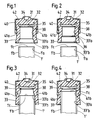
- Figure 1 shows a tube, a stopper and a compression ring combination of which the tube neck (1′) has a smooth cylindrical outer surface, and the stopper consists of a body of deformable material such as synthetic rubber, having a head (31) including a central dimple (34), and an integral skirt (33) extending flush from the generally cylindrical wall of the head.
- a self-sealing membrane (32) extends from the head as a central plug (38). This central plug is surrounded by an annular recess in the form of an inwardly facing annular groove (35) in the end of the skirt (33) adjacent the head (31).
- the inner wall of the skirt (33) is divided into two portions, an upper one (33′a), cylindrical and extending up to the groove 35), which is smooth and uninterrupted and seals around the tube neck (1′), and a lower one (33′b) extending to the edge of the skirt.
- An outer compression ring (40) made of plastic or similar resilience material is set at the periphery of the head (31) and extends downwardly around the skirt (33) at a level where it overlaps the upper cylindrical sealing portion (33′a),and fits against the peripheral wall (33) by the annular segment (41a).
- Figure 2 shows a tube,a stopper and a compression ring combination in which the upper cylindrical sealing portion (33′a) is connected to the lower cylindrical portion (33′b) of slightly larger diameter by a slanted section (36).
- the diameter of this upper cylindrical sealing portion (33′a) is significantly smaller than the outer diameter of the tube neck (1′).
- Figure 3 represents the entry of tube (1′) inside the sealing portion (33′a) of the stopper of figure 2.
- the thickness of at least one annular segment of the skirt wall (33),overlapped by the ring (40), is significantly larger than the breadth of space provided between the two concentric surfaces of the tube outer wall (1′b) and the ring inner wall (41a).
- the ring inner wall (41a) prevents the inherent deformation of the skirt outwardly induced.
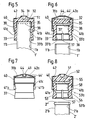
- the excess material is compressed upwardly and inwardly to form a resilient annular serration (39), at the interface of the annular groove (35) and of the sealing portion (33′a), against which the tube rim (1′c) comes to a stop, Fig.4.
- the annular groove (35) extends beyond the plug (38) and provides a deformation space for the annular serration (39) pressed upwardly by the tube rim (1′c), before absorption between the tube wall (1b) and the ring (40).
- the pressure needed to pass the tube rim over the resilient serration (39) is such that, once the resistance yields, under the impulse of the force released the tube enters into the annular recess space (35) and fully engages over the plug (38), achieving the automated clenching mechanism.
- Figure 6 shows a stopper of the same type as that of figure 2 in which the lower cylindrical portion (33′b) incorporates an axially directed groove (37),which extends from the skirt edge along this lower portion slightly into the upper portion (33′a) which otherwise is smooth and uninterrupted.
- the lower annular segment (41a) of the ring stops at distance above the outlet (37′) of this axial groove.
- the ring 40 differs from the previous representations by the abutments (42a) that extend as a cover, radially and inwardly from the peripheral wall of the ring to a central opening (44), acceeding to a chamber (44′) defined in its top by said cover (42a), and in its bottom by the flat surface (31b) of the stopper head.
- the cover with the narrow central opening (44) leading into a chamber (44′) protects the technician against contact with any trace of blood remaining on the head surface (31b) after the needle has been pulled out from the sealing membrane (32).
- the ring (40) incorporates vertical abutments (49) extending downwardly from the central opening (44) towards the head surface (31b). These abutments are able to transfer a pressure through the membrane (32) to the interior of the tube, when it is necessary to expell a drop of blood from the assembled sampling unit, for instance for making blood slides.
- the lower edge of the peripheral wall of the ring is provided with at least one axial cut-out (41c).
- Fig.8 shows a tube, a stopper and a compression ring combination in which the tube (2′) incorporates an outwardly projecting annular bead (2 ⁇ ), forming a rim on the open end of the tube neck.
- the skirt (53) is provided with a second annular groove (56) adjacent to the cylindrical sealing portion (53′a) and an axially directed groove (57) extends from the edge of the skirt along this lower portion inner surface slightly into the upper portion (53′a).
- This axially directed groove (57) has a deeper section than the annular groove at the place they intersect.
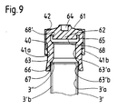
- Fig.9 shows a form of realisation in which the tube (3′) has a rim (3 ⁇ ) slightly protruding as an inward bead at the end of the neck.
- the stopper has an outwardly flaring groove (68′) inset in the periphery of the plug (68) sealibly engaging with the rim (3 ⁇ ).
- the lower cylindrical portion (63′b) of the stopper is larger in diameter than the tube diameter (3′b), thus providing a venting recess communicating the interior of the tube with the outside, prior to complete removal of the stopper.
- axially directed groove is intended to include grooves and similar recesses having major axial components to provide venting space between the tube outer wall and the skirt inner wall, in the lower portion of the skirt adjacent the cylindrical sealing portion.
Landscapes
- Health & Medical Sciences (AREA)
- Chemical & Material Sciences (AREA)
- Engineering & Computer Science (AREA)
- Mechanical Engineering (AREA)
- Analytical Chemistry (AREA)
- General Health & Medical Sciences (AREA)
- Hematology (AREA)
- Clinical Laboratory Science (AREA)
- Chemical Kinetics & Catalysis (AREA)
- Measurement Of The Respiration, Hearing Ability, Form, And Blood Characteristics Of Living Organisms (AREA)
Priority Applications (4)
| Application Number | Priority Date | Filing Date | Title |
|---|---|---|---|
| DE8888810201T DE3876237T2 (de) | 1988-03-25 | 1988-03-25 | Proberoehrchen, stopfen und kompressionsring fuer blutprobenentnahmesysteme. |
| ES198888810201T ES2036714T3 (es) | 1988-03-25 | 1988-03-25 | Tubo, tapon y anillo de compresion para sistemas de muestreo de sangre. |
| EP88810201A EP0333967B1 (de) | 1988-03-25 | 1988-03-25 | Proberöhrchen, Stopfen und Kompressionsring für Blutprobenentnahmesysteme |
| US07/324,915 US4923072A (en) | 1988-03-25 | 1989-03-17 | Tube, stopper and compression ring for blood sampling systems |
Applications Claiming Priority (1)
| Application Number | Priority Date | Filing Date | Title |
|---|---|---|---|
| EP88810201A EP0333967B1 (de) | 1988-03-25 | 1988-03-25 | Proberöhrchen, Stopfen und Kompressionsring für Blutprobenentnahmesysteme |
Publications (2)
| Publication Number | Publication Date |
|---|---|
| EP0333967A1 true EP0333967A1 (de) | 1989-09-27 |
| EP0333967B1 EP0333967B1 (de) | 1992-11-25 |
Family
ID=8200578
Family Applications (1)
| Application Number | Title | Priority Date | Filing Date |
|---|---|---|---|
| EP88810201A Expired EP0333967B1 (de) | 1988-03-25 | 1988-03-25 | Proberöhrchen, Stopfen und Kompressionsring für Blutprobenentnahmesysteme |
Country Status (4)
| Country | Link |
|---|---|
| US (1) | US4923072A (de) |
| EP (1) | EP0333967B1 (de) |
| DE (1) | DE3876237T2 (de) |
| ES (1) | ES2036714T3 (de) |
Cited By (2)
| Publication number | Priority date | Publication date | Assignee | Title |
|---|---|---|---|---|
| EP0617920A1 (de) * | 1993-03-31 | 1994-10-05 | Becton, Dickinson and Company | Verschluss für Blutentnahmeröhrchen mit kleinem Durchmesser |
| EP2030687A1 (de) * | 2007-08-13 | 2009-03-04 | Hamilton Bonaduz AG | Verschlussanordnung mit Schnappmechanismus |
Families Citing this family (12)
| Publication number | Priority date | Publication date | Assignee | Title |
|---|---|---|---|---|
| US5662230A (en) * | 1990-07-13 | 1997-09-02 | J. G. Finneran Associates | Crimp top seal for vials |
| US5772057A (en) * | 1990-07-13 | 1998-06-30 | J.G. Finneran Associates, Inc. | Crimp top seal for vials |
| US5232109A (en) * | 1992-06-02 | 1993-08-03 | Sterling Winthrop Inc. | Double-seal stopper for parenteral bottle |
| US5599302A (en) | 1995-01-09 | 1997-02-04 | Medi-Ject Corporation | Medical injection system and method, gas spring thereof and launching device using gas spring |
| US5643211A (en) | 1996-02-29 | 1997-07-01 | Medi-Ject Corporation | Nozzle assembly having a frangible plunger |
| US5921967A (en) | 1996-02-29 | 1999-07-13 | Medi-Ject Corporation | Plunger for nozzle assembly |
| US5722953A (en) | 1996-02-29 | 1998-03-03 | Medi-Ject Corporation | Nozzle assembly for injection device |
| US5697917A (en) | 1996-02-29 | 1997-12-16 | Medi-Ject Corporation | Nozzle assembly with adjustable plunger travel gap |
| US5800388A (en) | 1996-02-29 | 1998-09-01 | Medi-Ject Corporation | Plunger/ram assembly adapted for a fluid injector |
| US5865795A (en) | 1996-02-29 | 1999-02-02 | Medi-Ject Corporation | Safety mechanism for injection devices |
| US5875976A (en) | 1996-12-24 | 1999-03-02 | Medi-Ject Corporation | Locking mechanism for nozzle assembly |
| BRPI0601379A (pt) * | 2006-04-04 | 2007-12-04 | Biolog S A | dispositivo porta-tubo seringa concêntrico para extração de fluidops biológicos e para geração de vazio no tubo |
Citations (4)
| Publication number | Priority date | Publication date | Assignee | Title |
|---|---|---|---|---|
| FR1583447A (de) * | 1968-03-20 | 1969-10-31 | ||
| WO1980001047A1 (en) * | 1978-11-28 | 1980-05-29 | Dematex Dev & Invest | Tube and stopper for blood-sampling systems |
| DE3201691A1 (de) * | 1982-01-21 | 1983-09-08 | K.J. Steingass GmbH, 5275 Bergneustadt | Stopfen fuer behaelter und proberoehrchen |
| EP0102851A2 (de) * | 1982-09-08 | 1984-03-14 | Walter Sarstedt Geräte und Verbrauchsmaterial für Medizin und Wissenschaft | Behälterverschluss |
Family Cites Families (4)
| Publication number | Priority date | Publication date | Assignee | Title |
|---|---|---|---|---|
| US1509916A (en) * | 1924-09-30 | of springville | ||
| US1430685A (en) * | 1921-03-26 | 1922-10-03 | Sampson Robert William | Bottle cap |
| DE2813940A1 (de) * | 1977-04-23 | 1978-10-26 | Zensho Honma | Flaschenverschluss |
| US4133441A (en) * | 1978-03-23 | 1979-01-09 | Baxter Travenol Laboratories, Inc. | Injection site |
-
1988
- 1988-03-25 DE DE8888810201T patent/DE3876237T2/de not_active Expired - Fee Related
- 1988-03-25 EP EP88810201A patent/EP0333967B1/de not_active Expired
- 1988-03-25 ES ES198888810201T patent/ES2036714T3/es not_active Expired - Lifetime
-
1989
- 1989-03-17 US US07/324,915 patent/US4923072A/en not_active Expired - Fee Related
Patent Citations (4)
| Publication number | Priority date | Publication date | Assignee | Title |
|---|---|---|---|---|
| FR1583447A (de) * | 1968-03-20 | 1969-10-31 | ||
| WO1980001047A1 (en) * | 1978-11-28 | 1980-05-29 | Dematex Dev & Invest | Tube and stopper for blood-sampling systems |
| DE3201691A1 (de) * | 1982-01-21 | 1983-09-08 | K.J. Steingass GmbH, 5275 Bergneustadt | Stopfen fuer behaelter und proberoehrchen |
| EP0102851A2 (de) * | 1982-09-08 | 1984-03-14 | Walter Sarstedt Geräte und Verbrauchsmaterial für Medizin und Wissenschaft | Behälterverschluss |
Cited By (2)
| Publication number | Priority date | Publication date | Assignee | Title |
|---|---|---|---|---|
| EP0617920A1 (de) * | 1993-03-31 | 1994-10-05 | Becton, Dickinson and Company | Verschluss für Blutentnahmeröhrchen mit kleinem Durchmesser |
| EP2030687A1 (de) * | 2007-08-13 | 2009-03-04 | Hamilton Bonaduz AG | Verschlussanordnung mit Schnappmechanismus |
Also Published As
| Publication number | Publication date |
|---|---|
| US4923072A (en) | 1990-05-08 |
| ES2036714T3 (es) | 1993-06-01 |
| DE3876237T2 (de) | 1993-05-27 |
| EP0333967B1 (de) | 1992-11-25 |
| DE3876237D1 (de) | 1993-01-07 |
Similar Documents
| Publication | Publication Date | Title |
|---|---|---|
| US4923072A (en) | Tube, stopper and compression ring for blood sampling systems | |
| US4619651A (en) | Anti-aerosoling drug reconstitution device | |
| US4066067A (en) | Vial stopper for blood sampling device | |
| US5088996A (en) | Anti-aerosoling drug reconstitution device | |
| US8123736B2 (en) | Cap adapters for medicament vial and associated methods | |
| US8162914B2 (en) | Cap adapters for medicament vial and associated methods | |
| USRE40428E1 (en) | Syringe Having Needle Isolation Features | |
| US4194640A (en) | Vial and closure | |
| EP0623523B1 (de) | Verschluss, bestehend aus einem Stopfen und einer Schutzkappe | |
| EP0129029B1 (de) | Kontamination vermeidender Blutabnahmeröhrchenverschluss | |
| EP2540276B1 (de) | Verfahren zur Herstellung einer Rekonstitutionsvorrichtung | |
| CA1311978C (en) | Blood collection tube safety cap | |
| EP0070975B1 (de) | Hohlnadel zur Mehrfach-Blutabnahme | |
| EP0273114A1 (de) | Durch Computer erzeugter Verschlussstopfen | |
| US4089432A (en) | Vial and closure | |
| US4204606A (en) | Tube and stopper combination with venting structure | |
| WO2010093581A2 (en) | Cap adapters for medicament vial and associated methods | |
| US4274543A (en) | Vial and closure structure | |
| DE10205344A1 (de) | Hermetisch verschlossener Behälter mit durchstechbarem Zugangseinlass | |
| US4687479A (en) | Blood storage device | |
| US4331233A (en) | Activation closure for vial | |
| EP0022765B1 (de) | Röhre und stöpsel für blutabnahmesysteme | |
| US4637520A (en) | Test tube protector | |
| US4643198A (en) | Cap for a tube for extracting blood | |
| US4769025A (en) | Blood storage device |
Legal Events
| Date | Code | Title | Description |
|---|---|---|---|
| PUAI | Public reference made under article 153(3) epc to a published international application that has entered the european phase |
Free format text: ORIGINAL CODE: 0009012 |
|
| AK | Designated contracting states |
Kind code of ref document: A1 Designated state(s): AT BE CH DE ES FR GB GR IT LI LU NL SE |
|
| RBV | Designated contracting states (corrected) |
Designated state(s): DE ES FR GB IT |
|
| 17P | Request for examination filed |
Effective date: 19900315 |
|
| 17Q | First examination report despatched |
Effective date: 19910801 |
|
| RAP1 | Party data changed (applicant data changed or rights of an application transferred) |
Owner name: DEMATEX DEVELOPMENT & TRADING INC. C/O QUIJANO AND |
|
| GRAA | (expected) grant |
Free format text: ORIGINAL CODE: 0009210 |
|
| AK | Designated contracting states |
Kind code of ref document: B1 Designated state(s): DE ES FR GB IT |
|
| PG25 | Lapsed in a contracting state [announced via postgrant information from national office to epo] |
Ref country code: FR Free format text: THE PATENT HAS BEEN ANNULLED BY A DECISION OF A NATIONAL AUTHORITY Effective date: 19921125 |
|
| ITF | It: translation for a ep patent filed | ||
| REF | Corresponds to: |
Ref document number: 3876237 Country of ref document: DE Date of ref document: 19930107 |
|
| PG25 | Lapsed in a contracting state [announced via postgrant information from national office to epo] |
Ref country code: GB Effective date: 19930325 |
|
| PG25 | Lapsed in a contracting state [announced via postgrant information from national office to epo] |
Ref country code: ES Free format text: LAPSE BECAUSE OF NON-PAYMENT OF DUE FEES Effective date: 19930326 |
|
| EN | Fr: translation not filed | ||
| REG | Reference to a national code |
Ref country code: ES Ref legal event code: FG2A Ref document number: 2036714 Country of ref document: ES Kind code of ref document: T3 |
|
| EN | Fr: translation not filed |
Free format text: BO 15/93 PAGE 173: ANNULATION |
|
| ET | Fr: translation filed | ||
| PLBE | No opposition filed within time limit |
Free format text: ORIGINAL CODE: 0009261 |
|
| STAA | Information on the status of an ep patent application or granted ep patent |
Free format text: STATUS: NO OPPOSITION FILED WITHIN TIME LIMIT |
|
| 26N | No opposition filed | ||
| GBPC | Gb: european patent ceased through non-payment of renewal fee |
Effective date: 19930325 |
|
| PG25 | Lapsed in a contracting state [announced via postgrant information from national office to epo] |
Ref country code: DE Effective date: 19931201 |
|
| REG | Reference to a national code |
Ref country code: FR Ref legal event code: ST |
|
| REG | Reference to a national code |
Ref country code: ES Ref legal event code: FD2A Effective date: 19990301 |
|
| PG25 | Lapsed in a contracting state [announced via postgrant information from national office to epo] |
Ref country code: IT Free format text: LAPSE BECAUSE OF NON-PAYMENT OF DUE FEES Effective date: 20050325 |