EP0334043A1 - Unité portable pour manipuler et stocker des longueurs de matériau en forme de bande flexible - Google Patents
Unité portable pour manipuler et stocker des longueurs de matériau en forme de bande flexible Download PDFInfo
- Publication number
- EP0334043A1 EP0334043A1 EP89103130A EP89103130A EP0334043A1 EP 0334043 A1 EP0334043 A1 EP 0334043A1 EP 89103130 A EP89103130 A EP 89103130A EP 89103130 A EP89103130 A EP 89103130A EP 0334043 A1 EP0334043 A1 EP 0334043A1
- Authority
- EP
- European Patent Office
- Prior art keywords
- spools
- spool
- frame
- mandrels
- tread
- Prior art date
- Legal status (The legal status is an assumption and is not a legal conclusion. Google has not performed a legal analysis and makes no representation as to the accuracy of the status listed.)
- Withdrawn
Links
- 239000000463 material Substances 0.000 title claims abstract description 44
- 229910000831 Steel Inorganic materials 0.000 claims description 4
- 239000010959 steel Substances 0.000 claims description 4
- 238000007599 discharging Methods 0.000 claims 1
- 238000003860 storage Methods 0.000 abstract description 95
- 230000015572 biosynthetic process Effects 0.000 abstract 1
- 230000007246 mechanism Effects 0.000 description 25
- 230000033001 locomotion Effects 0.000 description 13
- 230000014759 maintenance of location Effects 0.000 description 9
- 238000010276 construction Methods 0.000 description 5
- 238000004519 manufacturing process Methods 0.000 description 4
- 229920001084 poly(chloroprene) Polymers 0.000 description 4
- 238000012546 transfer Methods 0.000 description 4
- 229910052782 aluminium Inorganic materials 0.000 description 3
- XAGFODPZIPBFFR-UHFFFAOYSA-N aluminium Chemical compound [Al] XAGFODPZIPBFFR-UHFFFAOYSA-N 0.000 description 3
- 238000010586 diagram Methods 0.000 description 3
- 239000004744 fabric Substances 0.000 description 3
- 238000012423 maintenance Methods 0.000 description 3
- 229920001971 elastomer Polymers 0.000 description 2
- 230000013011 mating Effects 0.000 description 2
- 238000012545 processing Methods 0.000 description 2
- 230000000717 retained effect Effects 0.000 description 2
- 230000002311 subsequent effect Effects 0.000 description 2
- 230000032258 transport Effects 0.000 description 2
- 230000032683 aging Effects 0.000 description 1
- 230000003679 aging effect Effects 0.000 description 1
- 238000003490 calendering Methods 0.000 description 1
- 229940000425 combination drug Drugs 0.000 description 1
- 230000006835 compression Effects 0.000 description 1
- 238000007906 compression Methods 0.000 description 1
- 238000001816 cooling Methods 0.000 description 1
- 230000001419 dependent effect Effects 0.000 description 1
- 238000013461 design Methods 0.000 description 1
- 238000001514 detection method Methods 0.000 description 1
- 230000009977 dual effect Effects 0.000 description 1
- 230000000694 effects Effects 0.000 description 1
- 238000001125 extrusion Methods 0.000 description 1
- 229910052751 metal Inorganic materials 0.000 description 1
- 239000002184 metal Substances 0.000 description 1
- 238000000034 method Methods 0.000 description 1
- 229920003023 plastic Polymers 0.000 description 1
- 239000004033 plastic Substances 0.000 description 1
- 230000002028 premature Effects 0.000 description 1
- 238000003908 quality control method Methods 0.000 description 1
- 230000001105 regulatory effect Effects 0.000 description 1
- 230000000284 resting effect Effects 0.000 description 1
- 238000005096 rolling process Methods 0.000 description 1
- 239000003381 stabilizer Substances 0.000 description 1
- 230000000087 stabilizing effect Effects 0.000 description 1
- 230000001360 synchronised effect Effects 0.000 description 1
- 238000003466 welding Methods 0.000 description 1
Images


Classifications
-
- B—PERFORMING OPERATIONS; TRANSPORTING
- B65—CONVEYING; PACKING; STORING; HANDLING THIN OR FILAMENTARY MATERIAL
- B65H—HANDLING THIN OR FILAMENTARY MATERIAL, e.g. SHEETS, WEBS, CABLES
- B65H75/00—Storing webs, tapes, or filamentary material, e.g. on reels
- B65H75/02—Cores, formers, supports, or holders for coiled, wound, or folded material, e.g. reels, spindles, bobbins, cop tubes, cans, mandrels or chucks
- B65H75/18—Constructional details
- B65H75/24—Constructional details adjustable in configuration, e.g. expansible
- B65H75/242—Expansible spindles, mandrels or chucks, e.g. for securing or releasing cores, holders or packages
- B65H75/243—Expansible spindles, mandrels or chucks, e.g. for securing or releasing cores, holders or packages actuated by use of a fluid
- B65H75/2437—Expansible spindles, mandrels or chucks, e.g. for securing or releasing cores, holders or packages actuated by use of a fluid comprising a fluid-pressure-actuated elastic member, e.g. a diaphragm or a pneumatic tube
-
- B—PERFORMING OPERATIONS; TRANSPORTING
- B29—WORKING OF PLASTICS; WORKING OF SUBSTANCES IN A PLASTIC STATE IN GENERAL
- B29C—SHAPING OR JOINING OF PLASTICS; SHAPING OF MATERIAL IN A PLASTIC STATE, NOT OTHERWISE PROVIDED FOR; AFTER-TREATMENT OF THE SHAPED PRODUCTS, e.g. REPAIRING
- B29C31/00—Handling, e.g. feeding of the material to be shaped, storage of plastics material before moulding; Automation, i.e. automated handling lines in plastics processing plants, e.g. using manipulators or robots
-
- B—PERFORMING OPERATIONS; TRANSPORTING
- B65—CONVEYING; PACKING; STORING; HANDLING THIN OR FILAMENTARY MATERIAL
- B65H—HANDLING THIN OR FILAMENTARY MATERIAL, e.g. SHEETS, WEBS, CABLES
- B65H16/00—Unwinding, paying-out webs
-
- B—PERFORMING OPERATIONS; TRANSPORTING
- B65—CONVEYING; PACKING; STORING; HANDLING THIN OR FILAMENTARY MATERIAL
- B65H—HANDLING THIN OR FILAMENTARY MATERIAL, e.g. SHEETS, WEBS, CABLES
- B65H18/00—Winding webs
-
- B—PERFORMING OPERATIONS; TRANSPORTING
- B65—CONVEYING; PACKING; STORING; HANDLING THIN OR FILAMENTARY MATERIAL
- B65H—HANDLING THIN OR FILAMENTARY MATERIAL, e.g. SHEETS, WEBS, CABLES
- B65H75/00—Storing webs, tapes, or filamentary material, e.g. on reels
- B65H75/02—Cores, formers, supports, or holders for coiled, wound, or folded material, e.g. reels, spindles, bobbins, cop tubes, cans, mandrels or chucks
- B65H75/04—Kinds or types
- B65H75/08—Kinds or types of circular or polygonal cross-section
- B65H75/14—Kinds or types of circular or polygonal cross-section with two end flanges
-
- B—PERFORMING OPERATIONS; TRANSPORTING
- B29—WORKING OF PLASTICS; WORKING OF SUBSTANCES IN A PLASTIC STATE IN GENERAL
- B29L—INDEXING SCHEME ASSOCIATED WITH SUBCLASS B29C, RELATING TO PARTICULAR ARTICLES
- B29L2030/00—Pneumatic or solid tyres or parts thereof
- B29L2030/002—Treads
-
- B—PERFORMING OPERATIONS; TRANSPORTING
- B65—CONVEYING; PACKING; STORING; HANDLING THIN OR FILAMENTARY MATERIAL
- B65H—HANDLING THIN OR FILAMENTARY MATERIAL, e.g. SHEETS, WEBS, CABLES
- B65H2301/00—Handling processes for sheets or webs
- B65H2301/40—Type of handling process
- B65H2301/41—Winding, unwinding
- B65H2301/413—Supporting web roll
- B65H2301/4136—Mounting arrangements not otherwise provided for
- B65H2301/41368—Mounting arrangements not otherwise provided for one or two lateral flanges covering part of or entire web diameter
-
- B—PERFORMING OPERATIONS; TRANSPORTING
- B65—CONVEYING; PACKING; STORING; HANDLING THIN OR FILAMENTARY MATERIAL
- B65H—HANDLING THIN OR FILAMENTARY MATERIAL, e.g. SHEETS, WEBS, CABLES
- B65H2301/00—Handling processes for sheets or webs
- B65H2301/40—Type of handling process
- B65H2301/41—Winding, unwinding
- B65H2301/414—Winding
- B65H2301/4143—Performing winding process
- B65H2301/41432—Performing winding process special features of winding process
- B65H2301/414324—Performing winding process special features of winding process involving interleaf web/sheet, e.g. liner
-
- B—PERFORMING OPERATIONS; TRANSPORTING
- B65—CONVEYING; PACKING; STORING; HANDLING THIN OR FILAMENTARY MATERIAL
- B65H—HANDLING THIN OR FILAMENTARY MATERIAL, e.g. SHEETS, WEBS, CABLES
- B65H2301/00—Handling processes for sheets or webs
- B65H2301/40—Type of handling process
- B65H2301/41—Winding, unwinding
- B65H2301/417—Handling or changing web rolls
- B65H2301/4171—Handling web roll
- B65H2301/4172—Handling web roll by circumferential portion, e.g. rolling on circumference
- B65H2301/41724—Handling web roll by circumferential portion, e.g. rolling on circumference by crane
-
- B—PERFORMING OPERATIONS; TRANSPORTING
- B65—CONVEYING; PACKING; STORING; HANDLING THIN OR FILAMENTARY MATERIAL
- B65H—HANDLING THIN OR FILAMENTARY MATERIAL, e.g. SHEETS, WEBS, CABLES
- B65H2403/00—Power transmission; Driving means
- B65H2403/30—Chain drives
-
- B—PERFORMING OPERATIONS; TRANSPORTING
- B65—CONVEYING; PACKING; STORING; HANDLING THIN OR FILAMENTARY MATERIAL
- B65H—HANDLING THIN OR FILAMENTARY MATERIAL, e.g. SHEETS, WEBS, CABLES
- B65H2405/00—Parts for holding the handled material
- B65H2405/40—Holders, supports for rolls
- B65H2405/42—Supports for rolls fully removable from the handling machine
- B65H2405/422—Trolley, cart, i.e. support movable on floor
-
- B—PERFORMING OPERATIONS; TRANSPORTING
- B65—CONVEYING; PACKING; STORING; HANDLING THIN OR FILAMENTARY MATERIAL
- B65H—HANDLING THIN OR FILAMENTARY MATERIAL, e.g. SHEETS, WEBS, CABLES
- B65H2701/00—Handled material; Storage means
- B65H2701/50—Storage means for webs, tapes, or filamentary material
- B65H2701/51—Cores or reels characterised by the material
- B65H2701/513—Cores or reels characterised by the material assembled mainly from rigid elements of the same kind
- B65H2701/5134—Metal elements
-
- B—PERFORMING OPERATIONS; TRANSPORTING
- B65—CONVEYING; PACKING; STORING; HANDLING THIN OR FILAMENTARY MATERIAL
- B65H—HANDLING THIN OR FILAMENTARY MATERIAL, e.g. SHEETS, WEBS, CABLES
- B65H2701/00—Handled material; Storage means
- B65H2701/50—Storage means for webs, tapes, or filamentary material
- B65H2701/51—Cores or reels characterised by the material
- B65H2701/515—Cores or reels characterised by the material assembled from parts made of different materials
-
- B—PERFORMING OPERATIONS; TRANSPORTING
- B65—CONVEYING; PACKING; STORING; HANDLING THIN OR FILAMENTARY MATERIAL
- B65H—HANDLING THIN OR FILAMENTARY MATERIAL, e.g. SHEETS, WEBS, CABLES
- B65H2801/00—Application field
- B65H2801/93—Tyres
Definitions
- the invention relates to a portable unit for handling and storing lengths of flexible strip material and in particular strip materials used in the manufacture of tires. are particularly, the invention relates to a portable storage unit at an extrusion site and which transports the strip material to a storage area and then to the tire making equipments in a simpler, more efficient manner than heretofore possible.
- An objective is to provide such portable storage units or packages containing the strip material at relatively low cost since a considerable number of such packages are required and used in a usual manufacturing operation in contrast to the more expensive drive units or equipment for loading and unloading the strip material in the packages.
- Another objective of the invention is to provide an improved portable storage unit for use in the improved system in which the unit is of an extremely simple, durable and rugged construction, free of components that require accurate alignment with the drive units at the loading and unloading stations, which reduces maintenance problems, yet which enables accurate alignment to be achieved with the load and unload equipment when at the respective load and unload stations.
- Another objective is to provide such an improved storage unit which can be loaded and unloaded in its usual vertical position but transported and stored in a horizontal position without effecting the alignment of the material containing spools within the unit in which the unit contains both a tread spool and a liner spool, in which the spools and connected liner material are protected within the unit from external hazards, and in which the unit is lighter in weight and less expensive to fabricate than prior portable spooltype storage units while providing reasonable life an maintenance requirements and which is compatible with existing sensing equipment for detecting when the spool is loaded or unloaded to control the operation of the associated drive equipment.
- Another objective of the invention is to provide such an improved system in which various types of automatic storage, retrieval and handling equipment can be used in the system and with the improved portable storage units and drive units; and in which the portable storage units can be moved into and out of engagement with the load and unload drive units in a continuous pass through a type of conveying system, or can be transported by AGV's, overhead lifting systems or the like, without affecting the operation of the drive units and portable storage unit.
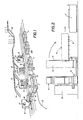
- a tire tread extruder line portion of the improved system is shown diagrammatically in FIG. 1 and includes a plurality of automatic guided vehicles (AGV) 1 located along an energized cable 2 which usually is embedded in the floor of the building.
- the AGV's are located adjacent a plurality of improved drive units, indicated generally at 3.
- One of the improved portable storage units is indicated generally at 4, and is shown mounted in a horizontal position on top of one of the AGV's prior to being transferred onto an upender 5 after which it is placed upon a transfer carriage assembly 6 of improved drive unit 3.
- Drive units 3, storage units 4 and carriage assembly 6 are shown in FIGS. 1 and 2 in diagrammatic form with the details of construction being shown in the other drawing figures and described below.
- the particular type of extruder line shown in FIG. 1 has a dual conveyor 8 for transporting two strips of material, hereinafter referred to as tread strips, through alternating gates 9 for loading onto a selected storage unit 4.
- a overhead lift mechanism (not shown) may be used as an alternate means of transferring a storage unit 4 from the AGV directly onto drive unit carriage 6 instead of upender 5.
- the particular extruder line shown in FIG. 1 is merely illustrative of one type of arrangement that can be used in the improved system.
- FIG. 2 is an enlarged elevation of the left hand end portion of FIG. 1 and shows in more detail the movement of one of the portable storage units 4 from its horizontal position on top of AGV 1 onto upender 5 which orients storage unit 4 from the horizontal to a vertical position on top of transfer carriage 6.
- Storage unit then is moved into engagement with drive unit 3 in a manner described in greater detail below.
- a similar type of drive unit 3, upender 5 and carriage assembly 6 can also be used at the tread unload station wherein a fully loaded portable storage unit 4 is moved by the equipment from a horizontal stored position into the vertical position for cooperative engagement with drive unit 3 for unloading the tire tread therefrom for use by a tire builder or for discharge into automatic tire making equipment.
- improved drive unit 3 is nearly identical in construction and operation when used both at the extruder line or tire tread load station as well as at the tire tread unload station. This eliminates multiple types of drive equipment with the resulting increased maintenance, spare parts inventory and other expenses, which are materially reduced by the ability to use the drive unit at both the load and unload stations.
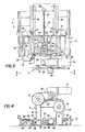
- Drive unit 3 includes as its main components a pair of fixed stands 15 and 16 on which are mounted a pair of pneumatic expandable mandrels 17 and 18, referred to as the tread spool mandrel and liner spool mandrel, respectively.
- a drive motor 19 is mounted on a base 20 which is supported by and extends between drive stands 15 and 16. Motor 19 is connected by a drive chain 21 to mandrel 17 when drive unit 3 is used at the loading station with a brake mechanism 22 being operatively connected with liner spool mandrel 18.
- drive chain 21 When drive unit 3 is used at the letoff or unload station, drive chain 21 will be connected to mandrel 18 with brake mechanism 22 being engaged with tread spool mandrel 17. Other than the reversal of drive chain 21 and brake mechanism 22, the drive unit will be the same for both the load and unload applications.
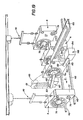
- carriage assembly 6 is mounted adjacent drive stands 15 and 16 for moving a portable storage unit 4 into operative engagement with mandrels 17 and 18 as described below.
- Carriage assembly 6 includes a carriage 25 having a base 26 which is movably supported by a plurality of wheels 27 on a pair of parallel rails 28. Wheels 27 preferably have an outer annular flange 29 which maintains the wheels and supported base in alignment on rails 28.
- a carriage platform 30 is vertically movably supported on base 26 by four air springs 31 located at the corners of the carriage assembly.
- Platform 30 includes a pair of spaced side rails 34 which extend transversely to the direction of travel of carriage 25 and has a plurality of rollers 35 rotatably mounted on and extending between rails 34.
- Rollers 35 enable a storage unit 4 to be moved transversely along platform to the aligned position with mandrels 17 and 18.
- Rollers 35 may be power driven rollers or idler rollers depending upon the particular material transfer equipment used in the improved system.
- Air springs 31 are usual components preferably cylindrically shaped, expandable rubber bags which are connected to appropriate air lines for filling the bags with air and for removing air therefrom to adjust the vertical height of the bag and correspondingly to adjust the vertical position of platform 30 on base 2
- the air springs are mounted on plates 32 which are attached to and extend outwardly from the ends of side rails 34.
- a pair of adjustable stops (FIG. 7) are located at the four corners of carriage 25 and extend between base 26 and platform 30 to limit the upward and downward vertical movement of the platform with respect to the base upon expanding and collapsing of air springs 31.
- Each of the pair of stops include an upstop 37 formed by a bolt 38 which is positioned with an opening formed in air spring mounting plate 32 by a pair of nuts 39.
- the lower end of bolt 38 extends through a hole 40 formed in another plate 41 which if spaced below air spring mounting plate 32.
- Another set of nuts 42 and washers are mounted at the lower end of bolt 38 for stopping the vertical upward movement
- a downstop indicated generally at 43 include a bolt 44 mounted within a hole 45 formed in plate 41 and is retained therein by a pair of nuts 46. The extended end 47 of bolt 44 engages plate 32 to stop the downward movement of carriage platform 30 upon the decrease of air pressure within air springs 31.
- Mechanism 50 includes a threaded shaft 5l rotatably at its out end by a bearing 52 and at its inner end by a bearing 53 (FIGS. 3-5).
- a drive pulley 54 is mounted on the inner end of shaft 51 and is connected to a drive motor 56 by a drive chain 55.
- Shaft 51 is operatively engaged with a nut 57 which is mounted on a bracket 58 supported by a pair of channels 59 which extend between another pair of stabilizing channels 60 attached to main carriage side rails 34.
- improved storage unit 4 provides an extremely simple, efficient and durable apparatus for storing a predetermined quantity of strip material, and which is compatible and adapted for use with improved drive units 3.
- Storage unit 4 eliminates the heretofore required precision and expensive mechanisms for rotatably mounting spools within the surrounding supporting frame structure.
- Storage unit 4 includes a framework case indicated generally at 65, formed by a plurality of horizontally and vertically extending tubular metal members which are connected together by welding,bolts or other types of fasteners.
- Case 65 includes a base for supporting the unit in a vertical upright position as shown in FIG. 8, which is formed by spaced, parallel side members 66 and spaced, parallel end members 67.
- case 65 The ends of case 65 are formed by a spaced pair of rear vertical extending tubular members 69 and a pair of spaced vertical front members 70.
- a pair of horizontally spaced side wall forming members 7l extend vertically upwardly from one of the base members 6 and a similar pair of members 72 extend upwardly from the opposite base member 66 and are connected at their upper ends by a rectangular shaped top frame member 74.
- the forward end of top frame member 74 is connected with front end members 70 by a pair of spaced parallel sloped members 75 and a cross member 76.
- case 65 provides an extremely rigid, light-weight and durable frame able to withstand considerable handling and abuse without damage.
- the sides, top, ends and bottom of case 65 can be covered with a rigid mesh screen or steel panels 77 as shown diagrammatically in FIGS. 1 and 19, to prevent foreign contaminates from entering the case and as a safety feature for workman handling the storage units or working closely adjacent thereto.
- case 65 may be supported on wheels or casters to allow towing or pushing of unit 4 manually or by mechanical means. Attachment hooks, eyes, slots or similar devices may be placed on case 65 to allow handling by fork lifts, overhead conveyors or the like.
- a pair of spools indicated generally at 78 and 79, and hereinafter referred to as the tread spool and liner spool, respectively, are loosely supported on cradles 80 and 81, respectively.
- Spools 78 and 79 are hollow cylindrical shaped steel members having longitudinally extending bores 82 and 83, respectively.
- a pair of annular radially outwardly extending retention flanges 84 and 85 are formed on the outer surface of tread spool 78 and are located a predetermined distance axially inwardly from the edges of the spool.
- a similar pair of flanges 87 and 88 are formed on the outer surface of liner spool 79 and are spaced axially inwardly from the spool edges.
- the longitudinal axes 90 and 91 of spools 78 and 79, respectively, extend parallel to each other as shown in FIG. 8, and are parallel with a floor or horizontal supporting surface when storage unit 4 is in a vertical upright load and unload position.
- the axes are perpendicular to the floor or supporting structure when unit 4 is in a horizontal position as shown in FIG. 12.
- Cradles 80 and 81 are formed by pairs of horizontally spaced vertically extending plates 93-94 and 95-96, respectively.
- Cradle plates 93-94 and 95-96 are formed with upper concave recesses 97 and 98, respectively, which loosely supports spools 78 and 79 therein as shown in FIGS. 8-11.
- a pair of horizontally extending retention frame members 100 and 101 are attached to sidewall forming members 71 and 72 and are located adjacent to and a short distance above spool 78.
- a similar pair of frame members 102 and 103 are located closely adjacent to and spaced a predetermined distance above liner spool 79 and extend horizontally between and are attached to side wall frame forming members 71 and 72 and end wall frame members 70.
- a liner spool brake mechanism indicated generally at 105 preferably is mounted on case 65 for engagement with liner spool 79 to prevent any rotation of the liner spool during storage and shipment thereby maintaining a constant predetermined tension on a strip of liner material indicated at 106, and shown in FIGS. 17-18.
- Brake mechanism 105 includes a U-shaped lever 107 which is pivotally mounted on horizontal frame members 102 and 103 by brackets 108 and pivot pins 109 which are connected to each leg 110 of lever 107.
- a concave brake shoe 112 having a friction pad 113 mounted thereon is pivotally mounted by a pin 114 and bracket 117 at the extended end of each lever leg 110.
- a compression coil spring 115 is mounted by a bolt 116 and a pair of washers 123 at each end of lever legs 110 and biases brake shoe 112 toward braking engagement with liner spool 79.
- a liner strip of sheet material preferably aluminum or certain types of plastic extends between and is connected to tread spool 78 and liner spool 79 as shown partially in FIG. 13.
- Liner 106 preferably is a light gage aluminum sheet and it enables the adjacent convolutions of the wrapped tire tread to be separated from each other to prevent the rubber from bonding or sticking together.
- a predetermined length of liner will extend between and be wrapped about the tread and liner spools with the ends of the liner being connected to a respective one of the spools.
- liner 106 is connected at its respective ends to spools 78 and 79 by a liner leader shown in FIG. 13 and indicated generally at 111.
- a predetermined length of fabric reinforced neoprene 118 is attached by rivets 119 or other attachment means to the end of liner 106.
- Another strip of neoprene 120 is attached to each of the respective spools and is connected to the adjacent neoprene strip 118 by mating strips of hook and loop fabrics 121 and 122 of the type distriheaded under the trademark Velcro. This attachment arrangement enables detecting mechanisms such as photoelectric devices 139 and 140 (FIGS.
- An empty storage unit 4 is placed by appropriate transporting mechanism, for example, as shown in FIG. 1 by the motion of power driven rails 124 mounted on top of AGV 1 onto upender 5.
- Upender 5 pivots unit 4 from its horizontal transported position to a vertical load position on carriage 25 with the carriage being in its extended position spaced away from drive unit 3.
- the improved storage unit 4 can be placed in a usual load and unload vertical position or in a horizontal position for storage and transportation in both an empty and filled condition without affecting the alignment of the spools or the tread material and liner stored therein. Also, storage unit 4 can be placed on either side in the horizontal position and can withstand considerable abuse and jarring movement without affecting the stored strip material and the subsequent removal or loading of such material from or into the unit.
- a similar pair of stop plates 127 preferably are mounted on horizontal retention members 102 and 103 as shown in FIG. 12 for retention engagement with annular flanges 87 and 88 of liner spool 79, especially in those applications when liner spool brake 105 is not used on storage unit 4.
- spools 78 and 79 are loosely retained and trapped within case 65 by the spool flanges in combination with the lower cradle plates and upper stop plates in addition to side wall forming support member pairs 71 and 72 and front end members 70 (FIG. 8). Also, when spools 78 and 79 are not being rotated by drive unit 3 in a manner described below, brake mechanism 105 will be engaged with liner spool 79 to maintain a predetermined tension on liner 106 in those storage unit arrangements where a brake mechanism is desired. The weight of larger tread spool 78 also will be sufficient to prevent premature and unwanted rotation of the spool when supported in cradle 80.
- an empty storage unit 4 will be moved in the direction of arrow A, FIG. 3, toward drive unit 3 upon operation of screw and nut drive mechanism 50 until the fixed horizontally extending mandrels 17 and 18 enter into bores 82 and 83 of spools 78 and 79, respectively.
- Carriage 25 will be advanced until the forward circular edge of each spool abuts against a disc 129 which is mounted on the outer end of each mandrel shaft 130. Carriage 25 will continue to advance a small amount until the outer spool stop plates 126 and 127 engage the upper portion of the associated spool flanges 85 and 88.
- an appropriate control mechanism such as a limit switch, photodetector or the like will stop the linear motion of carriage 25.
- each of the mandrels will include one or more annular, inflatable pneumatic tubes 132 which are mounted about a cylindrical mandrel base 133.
- FIGS. 14-16 illustrates tread spool 78 and mandrel 17 which will be similar to liner spool 79 and mandrel 18, therefore only one of the spools and mandrels are shown in detail.
- mandrel tubes 132 are inflated and expand into clamping engagement with the cylindrical interior surfaces of spools 78 and 79 as shown by dot-dash lines.
- carriage 25 After the mandrels are clamped within their respective spools, air springs 31 of carriage 25 are deflated whereby carriage platform 30 moves downwardly a predetermined distance regulated by downstops 43. This distance will be sufficient to unseat the spools from their supported position within the concave recesses of the cradle plates while still providing clearance between the tops of the spools and the adjacent retention frame members 100-103 as shown in FIG. 15.
- carriage 25 is moved a predetermined distance away from drive unit to disengage the contact between the outer annular spool retention flanges 85 and 88 with stop plates 126 and 127. This movement completely frees each of the spools from any contact with the surrounding case members and stop plates while retaining the spools supported on their respective mandrels as shown in FIG. 16 and in proper alignment with each other.
- Mandrel 17 then is rotated by drive motor 19 through shaft 130 which will cause the liner to move in the direction of arrow B (FIG. 17) from liner spool toward the tread spool for receiving a strip of tire tread material 137 thereon which is being fed into the interior of case 65 by usual feed equipment (arrow C).
- Liner 106 and tread 137 then is wound about spool 78 with liner material 106 being located between adjacent convolutions of tread material.
- Mandrel 17 will continue to rotate at a predetermined speed by motor 19, with the speed of rotation of mandrels 18 being synchronized therewith through braking mechanism 22, until a loading sensor 139 detects when the thread spool has reached a fully loaded position.
- Sensor 139 actuates the appropriate mechanisms which will stop the feed of the tread material and sever it adjacent the inlet of case 65 resulting in a completely filled and loaded storage unit 4.
- the lengths of spools 78 and 79 and location of their retention flange is designed so that the tread and liner are located between the flanges leaving the outer ends of the spools free of any liner or tread material.
- a similar sensor 138 will be positioned to detect the liner leader and start or end of the tire tread to effect other controls of drive units 3.
- Carriage platform 30 then is raised vertically by inflation of air springs 31 so that loaded tread spool 78 and liner spool 78 are resting in the concave recesses of the cradle plates.
- Mandrel tubes 132 then are deflated enabling the storage unit to be moved horizontally away from drive unit 3 upon movement of carriage 25 from its loading position adjacent the drive mandrels to an extended position for subsequent pickup by the appropriate material handling equipment.
- Liner spool brake mechanism 105 automatically reengages the liner spool outer surface located beyond the retention flanges 87-88 maintaining the desired tension on the liner with the weight of the tread spool preventing its movement or rotation on the cradle.
- storage unit 4 Another of the advantages of storage unit 4 is that mandrels 17 and 18 can be engaged within the bores of the spools from either side and the filled and/or empty storage unit can be placed horizontally on either side due to the symetrical arrangement of the stop plates and cradle plate and pairs of spool retaining flanges.
- the horizontal storage of a newly filled unit with tread material is desirable over the vertical storage since a better aging effect is achieved on the tread due to less weight being placed on the tread of the inner convolutions which occurs when aged and stored in a vertical position. When in the horizontal position the weight on the treads while cooling is uniform throughout all of the convolutions.
- FIG. 19 shows another manner in which improved portable storage units 4 may be used with a somewhat different type of drive unit than that described above.
- FIG. 19 illustrates either a load or an unload station in which the portable storage units 4 (shown in block diagram form) are moved by an overhead crane system 141 and placed onto a pair of rails 142.
- Storage units 4 may have wheels or rollers 143 mounted on the bottom thereof to provide the rolling or sliding movement along rails 142.
- Mandrels 145 and 146 are expandable and may be the pneumatic type described above for mandrels 17 and 18.
- the mandrels are mounted on the outer ends of a pair of arms 149 and 150 by disc-shaped mounting plates 151 and 152.
- Arms 149 and 150 are pivotally mounted on drive mechanisms 153 and 154, respectively, which contain the necessary components for pivotally moving arms 149 and 150 and for supplying the mandrels with the control air or other means for expanding the mandrels into clamping engagement with the interior of tread spool 78 and liner spool 79 in a somewhat similar manner as described above.
- the mandrels are pivoted into the spool engaging position as shown in full lines in FIG. 19, and the storage unit advanced in the direction of arrow D until the mandrels are telescopically inserted within the interior of the respective spools.
- the mandrels then are expanded into the gripping relationship with the spools.
- the storage unit then is lowered by some adjustment means in wheels 143 or the mandrel arms pivoted upwardly a sufficient amount to displace the spools from their supported positions within cradles 80 and 81.
- the appropriate mandrel then is rotated to either discharge tire tread 137 or load the spool with an incoming tread strip by movement along a conveyor 155.
- the mandrels are deflated and storage unit 4 moved rearwardly a sufficient distance to enable the mandrels to be pivoted out of the linear path of the storage units defined by rails 142 as shown in dot-dash lines in FIG. 19.
- the storage unit then continues to move in its forward direction where it is then retrieved by overhead crane system 141 or by other material handling equipment moving it to storage or to another designated work area.
- the improved system including portable storage unit 4 and drive unit 3 enables an arrangement whereby the alignment of the spools on which the strip material is stored and transported is not dependent upon structural integrity of the package or supporting frame and requires a minimal number of components to achieve mating the spools with the drive units.
- the present handling and storage equipment need not be designed to withstand extreme abuse since the storage unit is compatible with existing handling means and techniques, and the cost and design complexity of the system equipment which is furnished in very large quantities and in particular storage units 4, is as low as possible and relies on the system equipment which is furnished in smaller quantity, namely, drive units 3 and the material handling equipment to provide the accuracy to obtain the desired results.
- Storage unit 4 has a simplified construction, reduced cost and increased flexibility and can be provided with a simple brake mechanism to maintain liner tension during transit and storage. It can be stored horizontally on either side and will accommodate the wind-up and letoff drive/brake mechanism such as drive unit 3 from either side, and the liner leader attachment to the spools permits easy liner ends detection.
- the storage unit can be immediately placed in a horizontal position upon being loaded with a tread to insure better aging characteristics to the tread material than heretofore possible when aged in a vertical reel configuration.
- the improved system if desired, can be fully automated using AGV's or other automated storage and retrieval equipment which will move storage units 4 between drive units 3 located at the load and unload stations, all of which can be computer controlled reducing considerably the amount of manpower heretofore required for manually handling the tread material whether in predetermined cut lengths or even when in rolled form on prior spool configurations.
- the improved system and apparatus therefor is simplified, provides an effective, safe, inexpensive, and efficient means which achieves all the enumerated objectives, provides for eliminating difficulties encountered with prior systems and devices, and solves problems and obtains new results in the art.
Landscapes
- Engineering & Computer Science (AREA)
- Mechanical Engineering (AREA)
- Robotics (AREA)
- Tyre Moulding (AREA)
Priority Applications (1)
| Application Number | Priority Date | Filing Date | Title |
|---|---|---|---|
| EP89103130A EP0334043A1 (fr) | 1985-01-30 | 1985-11-04 | Unité portable pour manipuler et stocker des longueurs de matériau en forme de bande flexible |
Applications Claiming Priority (3)
| Application Number | Priority Date | Filing Date | Title |
|---|---|---|---|
| US696288 | 1985-01-30 | ||
| US06/696,288 US4609161A (en) | 1985-01-30 | 1985-01-30 | System and apparatus for storing and processing strip material |
| EP89103130A EP0334043A1 (fr) | 1985-01-30 | 1985-11-04 | Unité portable pour manipuler et stocker des longueurs de matériau en forme de bande flexible |
Related Parent Applications (1)
| Application Number | Title | Priority Date | Filing Date |
|---|---|---|---|
| EP85114016.0 Division | 1985-11-04 |
Publications (1)
| Publication Number | Publication Date |
|---|---|
| EP0334043A1 true EP0334043A1 (fr) | 1989-09-27 |
Family
ID=26119877
Family Applications (1)
| Application Number | Title | Priority Date | Filing Date |
|---|---|---|---|
| EP89103130A Withdrawn EP0334043A1 (fr) | 1985-01-30 | 1985-11-04 | Unité portable pour manipuler et stocker des longueurs de matériau en forme de bande flexible |
Country Status (1)
| Country | Link |
|---|---|
| EP (1) | EP0334043A1 (fr) |
Cited By (4)
| Publication number | Priority date | Publication date | Assignee | Title |
|---|---|---|---|---|
| DE10014842A1 (de) * | 2000-03-24 | 2001-09-27 | Heidelberger Druckmasch Ag | Vorrichtung zum Lagern, Transportieren und Zuführen von flächigem Bedruckstoff für eine diesen verarbeitende Maschine |
| EP1236669A1 (fr) * | 2001-02-20 | 2002-09-04 | The Goodyear Tire & Rubber Company | Appareil et procédé de stockage de matériau en bande |
| CN106735103A (zh) * | 2016-11-30 | 2017-05-31 | 天能电池(芜湖)有限公司 | 蓄电池板栅带横竖导向收卷装置 |
| CN117622963A (zh) * | 2024-01-25 | 2024-03-01 | 洛阳市大资塑业有限公司 | 一种吊袋机自动化收卷装置 |
Citations (4)
| Publication number | Priority date | Publication date | Assignee | Title |
|---|---|---|---|---|
| US1620844A (en) * | 1924-03-27 | 1927-03-15 | Walker Maurice | Spindle carriage and clutch |
| FR1551014A (fr) * | 1967-08-10 | 1968-12-27 | ||
| AU488868B2 (en) * | 1975-04-24 | 1976-10-28 | G. CARDINAL and RALPH V. CARDINAL FELIX | System, method and apparatus for processing raw rubber into strip stock for retreading tyres |
| DE8004622U1 (de) * | 1980-02-21 | 1980-06-04 | Th. Goldschmidt Ag, 4300 Essen | Spannvorrichtung |
-
1985
- 1985-11-04 EP EP89103130A patent/EP0334043A1/fr not_active Withdrawn
Patent Citations (4)
| Publication number | Priority date | Publication date | Assignee | Title |
|---|---|---|---|---|
| US1620844A (en) * | 1924-03-27 | 1927-03-15 | Walker Maurice | Spindle carriage and clutch |
| FR1551014A (fr) * | 1967-08-10 | 1968-12-27 | ||
| AU488868B2 (en) * | 1975-04-24 | 1976-10-28 | G. CARDINAL and RALPH V. CARDINAL FELIX | System, method and apparatus for processing raw rubber into strip stock for retreading tyres |
| DE8004622U1 (de) * | 1980-02-21 | 1980-06-04 | Th. Goldschmidt Ag, 4300 Essen | Spannvorrichtung |
Cited By (6)
| Publication number | Priority date | Publication date | Assignee | Title |
|---|---|---|---|---|
| DE10014842A1 (de) * | 2000-03-24 | 2001-09-27 | Heidelberger Druckmasch Ag | Vorrichtung zum Lagern, Transportieren und Zuführen von flächigem Bedruckstoff für eine diesen verarbeitende Maschine |
| US6663041B2 (en) | 2000-03-24 | 2003-12-16 | Heidelberger Druckmaschinen Ag | Apparatus for storing, transporting and delivering roll-formed flat printing material for a machine processing such material |
| EP1236669A1 (fr) * | 2001-02-20 | 2002-09-04 | The Goodyear Tire & Rubber Company | Appareil et procédé de stockage de matériau en bande |
| CN106735103A (zh) * | 2016-11-30 | 2017-05-31 | 天能电池(芜湖)有限公司 | 蓄电池板栅带横竖导向收卷装置 |
| CN117622963A (zh) * | 2024-01-25 | 2024-03-01 | 洛阳市大资塑业有限公司 | 一种吊袋机自动化收卷装置 |
| CN117622963B (zh) * | 2024-01-25 | 2024-04-09 | 洛阳市大资塑业有限公司 | 一种吊袋机自动化收卷装置 |
Similar Documents
| Publication | Publication Date | Title |
|---|---|---|
| JP3708126B2 (ja) | 物資の運搬装置及び方法 | |
| US4544319A (en) | Cargo transfer system | |
| JP2853284B2 (ja) | 輸送用キャリッジ | |
| CN111453468A (zh) | 一种快速自动装车系统及其控制方法 | |
| US5673869A (en) | Mount for a winding unit and apparatus for processing printed products | |
| US4609161A (en) | System and apparatus for storing and processing strip material | |
| JPH11199058A (ja) | フォーク駆動式荷役装置及び荷役方法 | |
| CN114789881A (zh) | 一种装车系统及其控制方法 | |
| US6264417B1 (en) | Flexible roll chucking assemblage and method | |
| CN115535654A (zh) | 一种嵌入式集装箱自动装卸车系统 | |
| EP0334043A1 (fr) | Unité portable pour manipuler et stocker des longueurs de matériau en forme de bande flexible | |
| JPH11130268A (ja) | フォーク移動式荷役装置及び荷役方法 | |
| SK287358B6 (sk) | Podávacie zariadenie na konfekčný bubon na výrobu plášťov pneumatík | |
| CN120308696B (zh) | 一种可移动式自动装车机 | |
| US1932955A (en) | Loading method and apparatus | |
| CA1258261A (fr) | Mecanisme d'entrainement pour dispositif de stockage et de traitement de materiau en forme de bande | |
| EP1236669A1 (fr) | Appareil et procédé de stockage de matériau en bande | |
| MXPA04002902A (es) | Maquina empaquetadora. | |
| CN114590544B (zh) | 一种高稳定性的货运装车系统及其控制方法 | |
| JP4198590B2 (ja) | 長尺塑性変形部材の保管方法および長尺塑性変形部材の保管装置 | |
| US5232173A (en) | Strip winding machine | |
| US20010038788A1 (en) | Dock lifting device | |
| JP3050678U (ja) | フォーク移動式荷役装置 | |
| US4082044A (en) | Adjustable fluid dunnage system | |
| CN223752058U (zh) | 一种便于卷料装卸的放卷装置 |
Legal Events
| Date | Code | Title | Description |
|---|---|---|---|
| PUAI | Public reference made under article 153(3) epc to a published international application that has entered the european phase |
Free format text: ORIGINAL CODE: 0009012 |
|
| 17P | Request for examination filed |
Effective date: 19890223 |
|
| AC | Divisional application: reference to earlier application |
Ref document number: 189532 Country of ref document: EP |
|
| AK | Designated contracting states |
Kind code of ref document: A1 Designated state(s): AT BE DE FR GB IT LU NL SE |
|
| 17Q | First examination report despatched |
Effective date: 19911128 |
|
| STAA | Information on the status of an ep patent application or granted ep patent |
Free format text: STATUS: THE APPLICATION IS DEEMED TO BE WITHDRAWN |
|
| 18D | Application deemed to be withdrawn |
Effective date: 19920409 |