EP0334080A1 - Liaison en "T" entre deux profils, en particulier une traverse et un montant d'une façade - Google Patents
Liaison en "T" entre deux profils, en particulier une traverse et un montant d'une façade Download PDFInfo
- Publication number
- EP0334080A1 EP0334080A1 EP89103797A EP89103797A EP0334080A1 EP 0334080 A1 EP0334080 A1 EP 0334080A1 EP 89103797 A EP89103797 A EP 89103797A EP 89103797 A EP89103797 A EP 89103797A EP 0334080 A1 EP0334080 A1 EP 0334080A1
- Authority
- EP
- European Patent Office
- Prior art keywords
- profile
- collar bolt
- connector
- plate
- transom
- Prior art date
- Legal status (The legal status is an assumption and is not a legal conclusion. Google has not performed a legal analysis and makes no representation as to the accuracy of the status listed.)
- Granted
Links
Images

Classifications
-
- E—FIXED CONSTRUCTIONS
- E04—BUILDING
- E04B—GENERAL BUILDING CONSTRUCTIONS; WALLS, e.g. PARTITIONS; ROOFS; FLOORS; CEILINGS; INSULATION OR OTHER PROTECTION OF BUILDINGS
- E04B2/00—Walls, e.g. partitions, for buildings; Wall construction with regard to insulation; Connections specially adapted to walls
- E04B2/88—Curtain walls
- E04B2/96—Curtain walls comprising panels attached to the structure through mullions or transoms
-
- E—FIXED CONSTRUCTIONS
- E04—BUILDING
- E04B—GENERAL BUILDING CONSTRUCTIONS; WALLS, e.g. PARTITIONS; ROOFS; FLOORS; CEILINGS; INSULATION OR OTHER PROTECTION OF BUILDINGS
- E04B2/00—Walls, e.g. partitions, for buildings; Wall construction with regard to insulation; Connections specially adapted to walls
- E04B2/88—Curtain walls
- E04B2/96—Curtain walls comprising panels attached to the structure through mullions or transoms
- E04B2/965—Connections of mullions and transoms
-
- F—MECHANICAL ENGINEERING; LIGHTING; HEATING; WEAPONS; BLASTING
- F16—ENGINEERING ELEMENTS AND UNITS; GENERAL MEASURES FOR PRODUCING AND MAINTAINING EFFECTIVE FUNCTIONING OF MACHINES OR INSTALLATIONS; THERMAL INSULATION IN GENERAL
- F16B—DEVICES FOR FASTENING OR SECURING CONSTRUCTIONAL ELEMENTS OR MACHINE PARTS TOGETHER, e.g. NAILS, BOLTS, CIRCLIPS, CLAMPS, CLIPS OR WEDGES; JOINTS OR JOINTING
- F16B2200/00—Constructional details of connections not covered for in other groups of this subclass
- F16B2200/20—Connections with hook-like parts gripping behind a blind side of an element to be connected
- F16B2200/205—Connections with hook-like parts gripping behind a blind side of an element to be connected the hook being a separate retainer
-
- Y—GENERAL TAGGING OF NEW TECHNOLOGICAL DEVELOPMENTS; GENERAL TAGGING OF CROSS-SECTIONAL TECHNOLOGIES SPANNING OVER SEVERAL SECTIONS OF THE IPC; TECHNICAL SUBJECTS COVERED BY FORMER USPC CROSS-REFERENCE ART COLLECTIONS [XRACs] AND DIGESTS
- Y10—TECHNICAL SUBJECTS COVERED BY FORMER USPC
- Y10T—TECHNICAL SUBJECTS COVERED BY FORMER US CLASSIFICATION
- Y10T403/00—Joints and connections
- Y10T403/46—Rod end to transverse side of member
Definitions
- the invention relates to a T-connection between two profiles, preferably a rung and a mullion profile of a facade, of which the rung profile and the mullion profile have an inner chamber and in the inner chamber of the rung profile on the front end facing the connecting joint, a longitudinal section U- Shaped connector is defined, which consists of a front plate provided with at least one guide bore for a spring-loaded collar bolt equipped with a rectangular stop plate and of plate-shaped legs extending from two opposite end plate edges, which extend adjacent to the associated inner surfaces of the rung profile, the collar bolt non-rotatably in the Guided connector body and protrudes through the connection joint and a hole in a wall of the post profile into the inner chamber of the post profile and is fixed relative to the post profile.
- T-connection is known (DE-0S 34 19 294.8), in which the plate-shaped legs of the U-shaped connector body in longitudinal section are provided with an adhesive before insertion into the rung profile and the connector body after insertion into a forehead end of the rung profile is secured by screws screwed into the rung profile in addition to the gluing between the legs and the inside of the rung profile.
- the known connector body is equipped with two collar bolts which are spring-loaded, have a rectangular stop plate and are guided in the connector body so as to be secured against rotation. These collar bolts penetrate when the rung profile is connected to a mullion profile through a bore in the inner chamber of the mullion profile and have a transverse bore through which a pin is driven from the outside through a mounting hole in the mullion profile in order to anchor the collar bolts to the mullion profile.
- the invention has for its object to design a T-connection of the type mentioned so that the T-connector can be fixed both in the rung profile and in the post profile in a simple manner without the connector body needs to be screwed to the rung profile and the collar bolt or the like with a pin inserted from the outside into the post profile. must be anchored in the inner chamber of the post profile.
- the collar bolt has at least one latching recess in the region of its length projecting beyond the end plate and between the plate-shaped legs a toggle-shaped bridge web is provided, which has a threaded bore for a tensioning screw with its head supported on the end wall is provided and the bridge web is composed of a central web part and web parts running at an obtuse angle to the legs and connected to the legs, the threaded bore for the tensioning screw being arranged in the middle web part.
- the legs covered with adhesive are attached to the assigned inner surfaces of the Pressed rung profile, so that when the adhesive sets, a perfect connection between the plate-shaped legs of the connector body and the rung profile is created.
- the collar bolt inserted through a bore into the inner chamber of the post profile can accommodate part of the bore wall in its locking recess, so that there is a positive connection between the collar bolt and the post profile.
- a screw or a spring-loaded locking pin can be used, which springs into a locking hole in the post profile.
- the collar bolt is equipped with two locking recesses arranged one behind the other in the longitudinal direction and offset at an angular distance of 180 ° to one another.
- the stop plate of the collar bolt is guided between cheeks, the free length of the bolt projecting beyond the end plate being less than the maximum guide distance of the cheeks when the stop plate is in contact with the stop surface of the connector.
- the collar bolt By pressing the collar bolt against the action of the spring in the connector body until the stop plate is outside the cheeks, the collar bolt can be rotated by 180 ° and released so that the stop plate under the action of the spring again in the area of the guide cheeks up to front stop is moved.
- the second locking recess can now be used for the positive connection of the bolt to the post profile.
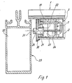
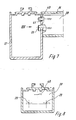
- a connector 3 is fixed at the front end of a rung profile 1 in its inner chamber 2, the structural design of which is shown in FIGS. 4 to 6.
- the connector body is U-shaped in longitudinal section and has an end plate 4, from which plate-shaped legs 5 extend on two side edges. These plate-shaped legs 5 have outwardly open recesses 6, which are used to hold an adhesive with which the legs of the connector body are covered before being inserted into the inner chamber of the rung profile 1.
- toggle-like bridge web 7 is provided, which is integral with the legs and consists of a central web part 8 and web parts 9, which start from the central web part 8 and extend to the legs 5 at an obtuse angle ⁇ .
- the central web part 8 is equipped with a threaded bore 10 for a clamping screw 11, which is supported with its head 12 on the end plate, specifically on the bottom 13 of a groove 14 provided in the end plate.
- This groove 14 extends over the entire height of the end plate 4.
- the bottom 13 is equipped with a through hole 15 for the threaded shaft of the clamping screw 11.
- 5 grooves 16, 17 are provided at the transition from the middle web part 8 to the web parts 9 and at the transition from the web parts 9 to the legs.
- an angle bar 18 is arranged, which has a strip part 19 running parallel to the central web part, is limited by the stroke of the clamping screw and thus the spreading of the legs 5.
- the bottom 13 is also provided with a through hole 20 for a collar bolt 21, in which the collar is formed by a stop plate 22 with a rectangular cross section.
- This stop plate is guided between cheeks 23, which start from the bottom 13 of the groove and extend in the direction of the bridge web 7.
- the cheeks 23 form a guideway with a length h2, while the length of the collar bolt part, which protrudes beyond the end plate when the stop plate 22 abuts the stop surface of the connector, is h1.
- h1 must be less than h2.
- the collar bolt 21 is assigned a spring 24 which extends through a bore 25 of the central web part 8 and is supported with its rear end on the strip part 19.
- the front end of the collar bolt 21 has two in the longitudinal direction equipped with recesses 26, 27 arranged one behind the other. These recesses are offset from one another at an angular distance of 180 °.
- the front end face of the collar bolt is equipped with a slot 28 for inserting a screwdriver.
- the collar bolt can be pressed against the action of the spring 24 into the interior of the connector body until the stop plate 22 is outside the cheeks 23.
- the collar bolt can then be rotated through 180 ° in order to bring the latching recess 26 into the lower position, in order then to use this latching recess when connecting the rung profile to the post profile.
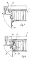
- the latching recess 26 is used for the positive connection of the collar bolt 21 with a post profile 29 in the embodiment according to FIGS. 1 and 2, in which a sealing collar 30 is arranged in the connection area.
- the front part of the collar bolt is inserted through a bore 31 into the inner chamber 32 of the post profile and then brought into the position shown in FIG. 2 for connecting the two profiles.
- a screw connection 33 is made between the two profiles in the region of the anchoring grooves 34 and 35 for sealing profiles.
- FIG. 7 and 8 show a further embodiment of a butt connection between the rung profile 36 and the post profile 37.
- the connector 38 is equipped with two collar bolts 39 lying next to one another in a plane and furthermore has a spring-loaded locking pin 40 which fits into one Bores 41 of the post profile.
Landscapes
- Engineering & Computer Science (AREA)
- Architecture (AREA)
- Physics & Mathematics (AREA)
- Electromagnetism (AREA)
- Civil Engineering (AREA)
- Structural Engineering (AREA)
- Joining Of Building Structures In Genera (AREA)
- Load-Bearing And Curtain Walls (AREA)
- Superconductors And Manufacturing Methods Therefor (AREA)
- Coupling Device And Connection With Printed Circuit (AREA)
- Mutual Connection Of Rods And Tubes (AREA)
- Fertilizing (AREA)
- Pressure Welding/Diffusion-Bonding (AREA)
- Mechanical Coupling Of Light Guides (AREA)
- Use Of Switch Circuits For Exchanges And Methods Of Control Of Multiplex Exchanges (AREA)
- Finishing Walls (AREA)
- Pharmaceuticals Containing Other Organic And Inorganic Compounds (AREA)
- Medicines Containing Antibodies Or Antigens For Use As Internal Diagnostic Agents (AREA)
- Standing Axle, Rod, Or Tube Structures Coupled By Welding, Adhesion, Or Deposition (AREA)
Priority Applications (1)
| Application Number | Priority Date | Filing Date | Title |
|---|---|---|---|
| AT89103797T ATE69078T1 (de) | 1988-03-24 | 1989-03-03 | T-verbindung zwischen zwei profilen, vorzugsweise einem sprossen- und einem pfostenprofil einer fassade. |
Applications Claiming Priority (2)
| Application Number | Priority Date | Filing Date | Title |
|---|---|---|---|
| DE3809951A DE3809951A1 (de) | 1988-03-24 | 1988-03-24 | T-verbindung zwischen zwei profilen, vorzugsweise einem sprossen- und einem pfostenprofil einer fassade |
| DE3809951 | 1988-03-24 |
Publications (2)
| Publication Number | Publication Date |
|---|---|
| EP0334080A1 true EP0334080A1 (fr) | 1989-09-27 |
| EP0334080B1 EP0334080B1 (fr) | 1991-10-30 |
Family
ID=6350589
Family Applications (1)
| Application Number | Title | Priority Date | Filing Date |
|---|---|---|---|
| EP89103797A Expired - Lifetime EP0334080B1 (fr) | 1988-03-24 | 1989-03-03 | Liaison en "T" entre deux profils, en particulier une traverse et un montant d'une façade |
Country Status (12)
| Country | Link |
|---|---|
| US (1) | US4948290A (fr) |
| EP (1) | EP0334080B1 (fr) |
| JP (1) | JP2880179B2 (fr) |
| KR (1) | KR960014624B1 (fr) |
| AT (1) | ATE69078T1 (fr) |
| CA (1) | CA1295591C (fr) |
| DE (2) | DE3809951A1 (fr) |
| DK (1) | DK167821B1 (fr) |
| ES (1) | ES2025824T3 (fr) |
| FI (1) | FI89618C (fr) |
| GR (1) | GR3003423T3 (fr) |
| NO (1) | NO172001C (fr) |
Cited By (12)
| Publication number | Priority date | Publication date | Assignee | Title |
|---|---|---|---|---|
| EP0733753A1 (fr) * | 1995-03-22 | 1996-09-25 | Firma J. Eberspächer | Connexion à traverses et montants, notamment pour la construction des façades en verre |
| EP2186959A3 (fr) * | 2008-11-12 | 2012-06-27 | Raico Bautechnik GmbH | Connexion en T entre un poteau profilé et une traverse profilée |
| ITMI20110658A1 (it) * | 2011-04-18 | 2012-10-19 | Ponzio Sud S R L | Dispositivo di bloccaggio di un traverso ad un montante di una facciata continua |
| WO2013163701A1 (fr) | 2012-04-20 | 2013-11-07 | Reynaers Aluminium, Naamloze Vennotschap | Raccord en t et raccordement en t effectué avec celui-ci |
| EP2642040A3 (fr) * | 2012-03-22 | 2014-04-30 | Norsk Hydro Asa | Connecteur, outil de montage et utilisation d'un connecteur |
| CN104695597A (zh) * | 2015-03-16 | 2015-06-10 | 杭州斯泰新材料技术有限公司 | 一种快装可拆销 |
| DE202014102053U1 (de) * | 2014-05-02 | 2015-08-17 | Raico Bautechnik Gmbh | T-Verbindung zwischen einem Pfosten- und Riegelprofil |
| DE202014102054U1 (de) * | 2014-05-02 | 2015-08-17 | Raico Bautechnik Gmbh | T-Verbindung zwischen einem Pfosten- und Riegelprofil |
| CN111024358A (zh) * | 2020-01-21 | 2020-04-17 | 中国空气动力研究与发展中心低速空气动力研究所 | 一种用于低速风洞试验的t型结构尾撑方法 |
| CN112502332A (zh) * | 2020-12-08 | 2021-03-16 | 中科建安工程有限公司 | 一种建筑工程幕墙安装用连接组件 |
| CN113374116A (zh) * | 2021-06-16 | 2021-09-10 | 黑龙江建筑职业技术学院 | 一种装配式墙体及其拼装方法 |
| EP2450496B1 (fr) * | 2010-11-08 | 2023-10-04 | Hydro Extruded Solutions As | Elément d'étanchéité |
Families Citing this family (12)
| Publication number | Priority date | Publication date | Assignee | Title |
|---|---|---|---|---|
| DE3938775A1 (de) * | 1989-11-23 | 1991-05-29 | Schueco Int Gmbh & Co | T-verbindung zwischen zwei profilen, vorzugsweise einem sprossen- und einem pfostenprofil einer fassade |
| DE9006344U1 (de) * | 1990-06-05 | 1990-09-06 | Bahr, Frank, 4952 Porta Westfalica | Vorrichtung zum lösbaren Verbinden von zwei Profilstäben |
| DE4210575A1 (de) * | 1992-03-31 | 1993-10-07 | Herbert Lacker | Unterkonstruktion für Glasdächer und Glasfassaden |
| DE19527141C2 (de) * | 1995-07-25 | 1998-07-09 | Evg Bauprofil System Entwicklungs & Vermarktungsgesellschaft Mbh | Pfosten-Sprossen-Konstruktion, insbesondere für Fassaden |
| DE19859886C1 (de) * | 1998-12-23 | 2000-11-30 | Manfred Muehle | Profilverbindung |
| DE19901775A1 (de) | 1999-01-18 | 2000-07-20 | Schueco Int Kg | T-Verbindung zwischen einem Sprossen- und einem Pfostenprofil einer Fassade oder eines Lichtdaches |
| DE20117100U1 (de) * | 2000-10-19 | 2002-04-18 | W. Hartmann & Co. (GmbH & Co.), 20459 Hamburg | Verbindungsvorrichtung zwischen einem Pfostenprofil und einem Riegelprofil für eine Bauwerksfassade |
| ITMI20021546A1 (it) * | 2002-07-12 | 2004-01-12 | Hydro Aluminium Systems Spa | Giunto per collegare fra loro due profilati e sistema per formare unacornice di una facciata o di un tetto di un edificio utilizzando tale |
| DE10321098B4 (de) * | 2003-05-09 | 2012-04-19 | Wicona Bausysteme Gmbh | Verbinder für Eck- oder Stoßverbindungen zweier Hohlprofile |
| BE1016889A3 (nl) * | 2005-12-12 | 2007-09-04 | Reynaers Aluminium Nv | Verbeterde t-verbinder. |
| DE102009008380A1 (de) * | 2009-02-11 | 2010-08-12 | SCHÜCO International KG | T-Verbindung |
| CN106836511A (zh) * | 2017-01-12 | 2017-06-13 | 马敬元 | 一种阳光房梁和立柱用的卯榫结构 |
Citations (3)
| Publication number | Priority date | Publication date | Assignee | Title |
|---|---|---|---|---|
| DE2550200B1 (de) * | 1975-11-08 | 1977-04-21 | Hartmann & Co W | Verbindungseinrichtung an zwei aneinander anliegenden profilstaeben |
| DE3228056A1 (de) * | 1982-07-27 | 1984-02-02 | Thyssen Plastik Anger KG, 8000 München | Verbindungselement |
| DE3419294A1 (de) * | 1984-05-24 | 1985-11-28 | SCHÜCO Heinz Schürmann GmbH & Co, 4800 Bielefeld | T-verbinder fuer einen sprossenstoss in einer vorsatzfassade |
Family Cites Families (5)
| Publication number | Priority date | Publication date | Assignee | Title |
|---|---|---|---|---|
| FR2376318A1 (fr) * | 1977-01-03 | 1978-07-28 | Leveque Xavier | Dispositif de liaison, notamment pour l'assemblage amovible d'elements profiles |
| FR2448065A1 (fr) * | 1979-01-30 | 1980-08-29 | Lauzier Rene | Dispositif d'assemblage de tubes de section carree ou rectangulaire formant un angle |
| SU838110A1 (ru) * | 1979-05-16 | 1981-06-15 | Musyakin Vyacheslav E | Замок дл креплени профилей |
| SE443601B (sv) * | 1982-04-22 | 1986-03-03 | Bo Allan Hjelm | Stellningssystem med inskjutbara skarvstycken och spiror med invendiga styrflensar for skarvstyckena |
| US4572694A (en) * | 1984-07-20 | 1986-02-25 | Otto Fastening Systems Ltd. | Structure member connector |
-
1988
- 1988-03-24 DE DE3809951A patent/DE3809951A1/de not_active Withdrawn
-
1989
- 1989-03-03 DE DE8989103797T patent/DE58900409D1/de not_active Expired - Fee Related
- 1989-03-03 EP EP89103797A patent/EP0334080B1/fr not_active Expired - Lifetime
- 1989-03-03 AT AT89103797T patent/ATE69078T1/de not_active IP Right Cessation
- 1989-03-03 ES ES198989103797T patent/ES2025824T3/es not_active Expired - Lifetime
- 1989-03-14 US US07/329,126 patent/US4948290A/en not_active Expired - Lifetime
- 1989-03-21 DK DK136789A patent/DK167821B1/da not_active IP Right Cessation
- 1989-03-21 NO NO891242A patent/NO172001C/no unknown
- 1989-03-23 FI FI891422A patent/FI89618C/fi not_active IP Right Cessation
- 1989-03-23 CA CA000594718A patent/CA1295591C/fr not_active Expired - Fee Related
- 1989-03-24 JP JP1070742A patent/JP2880179B2/ja not_active Expired - Fee Related
- 1989-03-24 KR KR1019890003748A patent/KR960014624B1/ko not_active Expired - Fee Related
-
1991
- 1991-12-23 GR GR91402119T patent/GR3003423T3/el unknown
Patent Citations (3)
| Publication number | Priority date | Publication date | Assignee | Title |
|---|---|---|---|---|
| DE2550200B1 (de) * | 1975-11-08 | 1977-04-21 | Hartmann & Co W | Verbindungseinrichtung an zwei aneinander anliegenden profilstaeben |
| DE3228056A1 (de) * | 1982-07-27 | 1984-02-02 | Thyssen Plastik Anger KG, 8000 München | Verbindungselement |
| DE3419294A1 (de) * | 1984-05-24 | 1985-11-28 | SCHÜCO Heinz Schürmann GmbH & Co, 4800 Bielefeld | T-verbinder fuer einen sprossenstoss in einer vorsatzfassade |
Cited By (14)
| Publication number | Priority date | Publication date | Assignee | Title |
|---|---|---|---|---|
| EP0733753A1 (fr) * | 1995-03-22 | 1996-09-25 | Firma J. Eberspächer | Connexion à traverses et montants, notamment pour la construction des façades en verre |
| EP2186959A3 (fr) * | 2008-11-12 | 2012-06-27 | Raico Bautechnik GmbH | Connexion en T entre un poteau profilé et une traverse profilée |
| EP2450496B1 (fr) * | 2010-11-08 | 2023-10-04 | Hydro Extruded Solutions As | Elément d'étanchéité |
| ITMI20110658A1 (it) * | 2011-04-18 | 2012-10-19 | Ponzio Sud S R L | Dispositivo di bloccaggio di un traverso ad un montante di una facciata continua |
| EP2642040A3 (fr) * | 2012-03-22 | 2014-04-30 | Norsk Hydro Asa | Connecteur, outil de montage et utilisation d'un connecteur |
| WO2013163701A1 (fr) | 2012-04-20 | 2013-11-07 | Reynaers Aluminium, Naamloze Vennotschap | Raccord en t et raccordement en t effectué avec celui-ci |
| BE1020554A3 (nl) * | 2012-04-20 | 2013-12-03 | Reynaers Aluminium Nv | T-verbinder en t-verbinding daarmee gerealiseerd. |
| DE202014102053U1 (de) * | 2014-05-02 | 2015-08-17 | Raico Bautechnik Gmbh | T-Verbindung zwischen einem Pfosten- und Riegelprofil |
| DE202014102054U1 (de) * | 2014-05-02 | 2015-08-17 | Raico Bautechnik Gmbh | T-Verbindung zwischen einem Pfosten- und Riegelprofil |
| CN104695597A (zh) * | 2015-03-16 | 2015-06-10 | 杭州斯泰新材料技术有限公司 | 一种快装可拆销 |
| CN111024358A (zh) * | 2020-01-21 | 2020-04-17 | 中国空气动力研究与发展中心低速空气动力研究所 | 一种用于低速风洞试验的t型结构尾撑方法 |
| CN112502332A (zh) * | 2020-12-08 | 2021-03-16 | 中科建安工程有限公司 | 一种建筑工程幕墙安装用连接组件 |
| CN112502332B (zh) * | 2020-12-08 | 2022-02-15 | 中科建安工程有限公司 | 一种建筑工程幕墙安装用连接组件 |
| CN113374116A (zh) * | 2021-06-16 | 2021-09-10 | 黑龙江建筑职业技术学院 | 一种装配式墙体及其拼装方法 |
Also Published As
| Publication number | Publication date |
|---|---|
| FI89618B (fi) | 1993-07-15 |
| DK136789D0 (da) | 1989-03-21 |
| DK136789A (da) | 1989-09-25 |
| NO172001C (no) | 1993-05-26 |
| JPH0224434A (ja) | 1990-01-26 |
| FI89618C (fi) | 1993-10-25 |
| FI891422A0 (fi) | 1989-03-23 |
| KR960014624B1 (ko) | 1996-10-19 |
| FI891422A7 (fi) | 1989-09-25 |
| DE58900409D1 (de) | 1991-12-05 |
| EP0334080B1 (fr) | 1991-10-30 |
| ATE69078T1 (de) | 1991-11-15 |
| JP2880179B2 (ja) | 1999-04-05 |
| KR890014904A (ko) | 1989-10-25 |
| NO891242L (no) | 1989-09-25 |
| NO891242D0 (no) | 1989-03-21 |
| DE3809951A1 (de) | 1989-10-05 |
| CA1295591C (fr) | 1992-02-11 |
| US4948290A (en) | 1990-08-14 |
| NO172001B (no) | 1993-02-15 |
| DK167821B1 (da) | 1993-12-20 |
| ES2025824T3 (es) | 1992-04-01 |
| GR3003423T3 (en) | 1993-02-17 |
Similar Documents
| Publication | Publication Date | Title |
|---|---|---|
| EP0334080B1 (fr) | Liaison en "T" entre deux profils, en particulier une traverse et un montant d'une façade | |
| EP0528213B1 (fr) | Elément de ferrure fixé par serrage dans une gorge profilée ayant au moins une contre-dépouille | |
| DE2618442C2 (de) | Stütze für ein Geländer oder dergleichen | |
| EP1020575A2 (fr) | Connection en T entre un poteau et une traverse profilés d'une façade ou d'une toiture vitrée | |
| DE102005044980B4 (de) | Stoßverbinder für Holz-/Aluminiumfassaden | |
| DE102021005130A1 (de) | Profilkopplungsanordnung | |
| DE2626580C2 (de) | Anschlußstück | |
| DE4210575A1 (de) | Unterkonstruktion für Glasdächer und Glasfassaden | |
| EP0429931B1 (fr) | Connexion en T entre montants et traverses d'une fassade | |
| EP0067970B1 (fr) | Dispositif de fixation pour éléments de façade | |
| DE2636434B2 (de) | Rahmeneckverbindung | |
| EP0057662A2 (fr) | Ferrure pour l'assemblage démontable d'éléments de construction en forme de dalle | |
| DE19822103A1 (de) | Fassadensystem für die Verkleidung eines Bauwerkes | |
| DE9012607U1 (de) | Klemmelement für eine Klemmvorrichtung | |
| EP0057833A1 (fr) | Fenêtre ou porte à armatures placées dans les coins des zones d'espace entre traverse dormante et châssis du battant | |
| DE3315423C2 (fr) | ||
| EP0814215B1 (fr) | Système de façades et de système de fixation | |
| EP1342861B1 (fr) | Dispositif de fixation | |
| DE9212546U1 (de) | Rohrgestell | |
| DE3147092C2 (de) | Verbindungssystem mit wenigstens einem Eckbogenelement | |
| DE3103291A1 (de) | An blend- und fluegelrahmen von fenstern, tueren od.dgl. ansetzbares verbindungselement | |
| DE19860743C1 (de) | Wandhalter für Verkleidungstafeln, insbesondere Fassadenelemente | |
| DE8400332U1 (de) | Eck- oder stossverbinder fuer bauprofile | |
| DE4421107A1 (de) | Vorrichtung zur Verbindung von Profilleisten | |
| DE9306516U1 (de) | Rahmenkonstruktion insbesondere für Fassadenverkleidungen |
Legal Events
| Date | Code | Title | Description |
|---|---|---|---|
| PUAI | Public reference made under article 153(3) epc to a published international application that has entered the european phase |
Free format text: ORIGINAL CODE: 0009012 |
|
| AK | Designated contracting states |
Kind code of ref document: A1 Designated state(s): AT BE CH DE ES FR GB GR IT LI LU NL SE |
|
| 17P | Request for examination filed |
Effective date: 19890816 |
|
| 17Q | First examination report despatched |
Effective date: 19910107 |
|
| ITF | It: translation for a ep patent filed | ||
| GRAA | (expected) grant |
Free format text: ORIGINAL CODE: 0009210 |
|
| AK | Designated contracting states |
Kind code of ref document: B1 Designated state(s): AT BE CH DE ES FR GB GR IT LI LU NL SE |
|
| REF | Corresponds to: |
Ref document number: 69078 Country of ref document: AT Date of ref document: 19911115 Kind code of ref document: T |
|
| GBT | Gb: translation of ep patent filed (gb section 77(6)(a)/1977) | ||
| REF | Corresponds to: |
Ref document number: 58900409 Country of ref document: DE Date of ref document: 19911205 |
|
| ET | Fr: translation filed | ||
| REG | Reference to a national code |
Ref country code: ES Ref legal event code: FG2A Ref document number: 2025824 Country of ref document: ES Kind code of ref document: T3 |
|
| PLBE | No opposition filed within time limit |
Free format text: ORIGINAL CODE: 0009261 |
|
| STAA | Information on the status of an ep patent application or granted ep patent |
Free format text: STATUS: NO OPPOSITION FILED WITHIN TIME LIMIT |
|
| 26N | No opposition filed | ||
| REG | Reference to a national code |
Ref country code: GR Ref legal event code: FG4A Free format text: 3003423 |
|
| EPTA | Lu: last paid annual fee | ||
| EAL | Se: european patent in force in sweden |
Ref document number: 89103797.0 |
|
| REG | Reference to a national code |
Ref country code: GB Ref legal event code: IF02 |
|
| PGFP | Annual fee paid to national office [announced via postgrant information from national office to epo] |
Ref country code: SE Payment date: 20050323 Year of fee payment: 17 |
|
| PGFP | Annual fee paid to national office [announced via postgrant information from national office to epo] |
Ref country code: LU Payment date: 20050325 Year of fee payment: 17 |
|
| PG25 | Lapsed in a contracting state [announced via postgrant information from national office to epo] |
Ref country code: SE Free format text: LAPSE BECAUSE OF NON-PAYMENT OF DUE FEES Effective date: 20060304 |
|
| PG25 | Lapsed in a contracting state [announced via postgrant information from national office to epo] |
Ref country code: LU Free format text: LAPSE BECAUSE OF NON-PAYMENT OF DUE FEES Effective date: 20060331 |
|
| PGFP | Annual fee paid to national office [announced via postgrant information from national office to epo] |
Ref country code: IT Payment date: 20060331 Year of fee payment: 18 |
|
| EUG | Se: european patent has lapsed | ||
| PGFP | Annual fee paid to national office [announced via postgrant information from national office to epo] |
Ref country code: NL Payment date: 20070319 Year of fee payment: 19 |
|
| PGFP | Annual fee paid to national office [announced via postgrant information from national office to epo] |
Ref country code: AT Payment date: 20070323 Year of fee payment: 19 Ref country code: BE Payment date: 20070323 Year of fee payment: 19 Ref country code: ES Payment date: 20070323 Year of fee payment: 19 Ref country code: GB Payment date: 20070323 Year of fee payment: 19 |
|
| PGFP | Annual fee paid to national office [announced via postgrant information from national office to epo] |
Ref country code: CH Payment date: 20070329 Year of fee payment: 19 |
|
| PGFP | Annual fee paid to national office [announced via postgrant information from national office to epo] |
Ref country code: DE Payment date: 20070521 Year of fee payment: 19 |
|
| PGFP | Annual fee paid to national office [announced via postgrant information from national office to epo] |
Ref country code: GR Payment date: 20070323 Year of fee payment: 19 |
|
| PGFP | Annual fee paid to national office [announced via postgrant information from national office to epo] |
Ref country code: FR Payment date: 20070321 Year of fee payment: 19 |
|
| BERE | Be: lapsed |
Owner name: *SCHUCO INTERNATIONAL G.M.B.H. & CO. Effective date: 20080331 |
|
| REG | Reference to a national code |
Ref country code: CH Ref legal event code: PL |
|
| GBPC | Gb: european patent ceased through non-payment of renewal fee |
Effective date: 20080303 |
|
| PG25 | Lapsed in a contracting state [announced via postgrant information from national office to epo] |
Ref country code: AT Free format text: LAPSE BECAUSE OF NON-PAYMENT OF DUE FEES Effective date: 20080303 Ref country code: NL Free format text: LAPSE BECAUSE OF NON-PAYMENT OF DUE FEES Effective date: 20081001 |
|
| NLV4 | Nl: lapsed or anulled due to non-payment of the annual fee |
Effective date: 20081001 |
|
| REG | Reference to a national code |
Ref country code: FR Ref legal event code: ST Effective date: 20081125 |
|
| PG25 | Lapsed in a contracting state [announced via postgrant information from national office to epo] |
Ref country code: LI Free format text: LAPSE BECAUSE OF NON-PAYMENT OF DUE FEES Effective date: 20080331 Ref country code: DE Free format text: LAPSE BECAUSE OF NON-PAYMENT OF DUE FEES Effective date: 20081001 Ref country code: CH Free format text: LAPSE BECAUSE OF NON-PAYMENT OF DUE FEES Effective date: 20080331 |
|
| PG25 | Lapsed in a contracting state [announced via postgrant information from national office to epo] |
Ref country code: BE Free format text: LAPSE BECAUSE OF NON-PAYMENT OF DUE FEES Effective date: 20080331 |
|
| PG25 | Lapsed in a contracting state [announced via postgrant information from national office to epo] |
Ref country code: FR Free format text: LAPSE BECAUSE OF NON-PAYMENT OF DUE FEES Effective date: 20080331 |
|
| REG | Reference to a national code |
Ref country code: ES Ref legal event code: FD2A Effective date: 20080304 |
|
| PG25 | Lapsed in a contracting state [announced via postgrant information from national office to epo] |
Ref country code: GR Free format text: LAPSE BECAUSE OF NON-PAYMENT OF DUE FEES Effective date: 20081002 Ref country code: GB Free format text: LAPSE BECAUSE OF NON-PAYMENT OF DUE FEES Effective date: 20080303 |
|
| PG25 | Lapsed in a contracting state [announced via postgrant information from national office to epo] |
Ref country code: ES Free format text: LAPSE BECAUSE OF NON-PAYMENT OF DUE FEES Effective date: 20080304 |
|
| PG25 | Lapsed in a contracting state [announced via postgrant information from national office to epo] |
Ref country code: IT Free format text: LAPSE BECAUSE OF NON-PAYMENT OF DUE FEES Effective date: 20070303 |