EP0334085A1 - Tuyère de remplissage pour machines, dispositifs et autres pour le remplissage de sacs à valve - Google Patents
Tuyère de remplissage pour machines, dispositifs et autres pour le remplissage de sacs à valve Download PDFInfo
- Publication number
- EP0334085A1 EP0334085A1 EP89103849A EP89103849A EP0334085A1 EP 0334085 A1 EP0334085 A1 EP 0334085A1 EP 89103849 A EP89103849 A EP 89103849A EP 89103849 A EP89103849 A EP 89103849A EP 0334085 A1 EP0334085 A1 EP 0334085A1
- Authority
- EP
- European Patent Office
- Prior art keywords
- outer tube
- filler neck
- filling
- valve
- air
- Prior art date
- Legal status (The legal status is an assumption and is not a legal conclusion. Google has not performed a legal analysis and makes no representation as to the accuracy of the status listed.)
- Granted
Links
- 239000000463 material Substances 0.000 claims abstract description 28
- 239000000945 filler Substances 0.000 claims description 31
- 238000000605 extraction Methods 0.000 claims description 5
- 230000000903 blocking effect Effects 0.000 claims description 4
- 230000035515 penetration Effects 0.000 claims 1
- 238000005429 filling process Methods 0.000 description 5
- 230000009172 bursting Effects 0.000 description 3
- 238000004026 adhesive bonding Methods 0.000 description 2
- 238000010276 construction Methods 0.000 description 2
- 238000003466 welding Methods 0.000 description 2
- 230000015572 biosynthetic process Effects 0.000 description 1
- 239000002184 metal Substances 0.000 description 1
Images

Classifications
-
- B—PERFORMING OPERATIONS; TRANSPORTING
- B65—CONVEYING; PACKING; STORING; HANDLING THIN OR FILAMENTARY MATERIAL
- B65B—MACHINES, APPARATUS OR DEVICES FOR, OR METHODS OF, PACKAGING ARTICLES OR MATERIALS; UNPACKING
- B65B1/00—Packaging fluent solid material, e.g. powders, granular or loose fibrous material, loose masses of small articles, in individual containers or receptacles, e.g. bags, sacks, boxes, cartons, cans, or jars
- B65B1/04—Methods of, or means for, filling the material into the containers or receptacles
- B65B1/18—Methods of, or means for, filling the material into the containers or receptacles for filling valve-bags
Definitions
- the invention relates to a filler neck for machines, devices of the like for filling valve bags with, in particular, powdery material, consisting of an inner tube guiding the filling material flow and an outer tube surrounding the inner tube at a distance for the purpose of forming an air-guiding channel therebetween.
- the push-on area of the outer tube is designed such that it comprises an axial section which can be expanded in diameter. Furthermore, the air-guiding channel formed between these two tubes can be connected to a compressed air source. If a valve sack to be filled with powdery or free-flowing, usually air-fluidized, filling material has been placed on the push-on section of the filling nozzle, compressed air is directed into the channel mentioned.
- the expandable section expands in a crowned manner from the outside and only comes into contact with the system over a short axial distance against the inner wall of the valve of the bag to be filled.
- the object of the invention is to improve a filler neck of the type mentioned in such a way that the valve of the attached valve bag for the filling process lies closely against the filler neck for a very long distance and that the valve or the bag in the valve area does not require any further treatment after filling .
- the solution to this problem is based on the filler neck mentioned in the introduction and is further characterized in that the outer tube is rigid in its push-on area receiving the valve of the valve bag and is provided with openings for the application of negative pressure in the channel.
- valve of a valve bag attached to the filler neck according to the invention bears along the contact between the neck and valve over a very large axial distance at the neck, so that no filling material can penetrate into the valve during the filling process and this
- the valve closes securely after being removed from the filler neck. This prevents the filling material from exiting the valve in the form of a small but steady stream after filling and contaminating its surroundings, including people.
- the extraordinarily good contact between the filler neck designed according to the invention and the valve inner wall is also achieved in that the annular channel formed between the two tubes is subjected to negative pressure, as a result of which the valve inner wall is sucked onto the filler neck essentially over its entire length. An additional welding or gluing of the valve after filling is therefore not necessary.
- a preferred embodiment of the invention consists in that the openings consist of slots which are provided at a distance from one another around the circumference of the outer tube, the slots being able to extend inclined to the longitudinal axis of the outer tube such that they - seen in the axial projection direction - their ends are at least adjacent to one another in the circumferential direction to form an uninterrupted air extraction zone.
- This configuration is very effective and can be produced with little effort.
- the outlet end of the inner tube and the outer tube is designed in the form of a cone or a truncated cone, both the cone and the truncated cone each having at least one outlet opening for the filling material in their downward-pointing region.
- the inner tube can be designed to be rotatable about its longitudinal axis in order to be able to close the outlet end of the filler neck, and the outer tube advantageously also has a hole.
- the risk of a sack bursting during filling is at least substantially reduced because the air escaping from the filling material can also be discharged via the channel between the two tubes.
- the perforation in the region of the valve can be dispensed with and the valve can be made simpler. There is also no longer any danger of filling material escaping from a perforation.
- the filling material emerges from the filling neck essentially vertically and not in a relatively large arc.
- the filling cone of the filling material builds up essentially in the middle of the bag with the advantage that less free space remains in the upper part of the bag after filling, so that the bags can have a smaller height dimension with otherwise the same width and thickness due to the better filling levels.
- better filling of the bags also results in better stackability of the bags on pallets, shelves or the like.
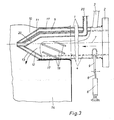
- the filler neck consists of an outer tube 1 with a mounting flange 2 at its inlet end and with a suction pipe connection 3 in the vicinity of the flange and an inner tube 4, which has a smaller diameter, such that an air-conducting channel between it and the outer tube 1 5 is formed.
- the inner tube which is arranged coaxially to the rigid outer tube, is rotatably mounted in the flange 2 and can be rotated by a certain amount by means of a cylinder 6 about the longitudinal axis 7 of the filler neck in order to close outlet openings which are still to be explained.
- the piston rod 8 of the cylinder 6 engages a lever 9 which is rigidly attached to the inner tube 4.
- the outer tube 1 is recessed accordingly and sealed with respect to the inner tube 4, as shown in FIG. 1.
- the inner tube 4 and the outer tube 1 are designed in the region of their outlet end in such a way that they are otherwise closed-walled while leaving an outlet region for the filling material.
- a cone formation 10, 11 is provided for both tubes 1,4, which are circular in cross section, the cones likewise being spaced apart from one another so that there is air between them can flow.
- the cones 10, 11 there are two outlet openings 12, 13 for the filling material, in their downward-facing area, as can best be seen from FIG. 3.
- cones 10, 11, truncated cones can also be provided, or any other form of training with corresponding outlet openings.
- two openings 12, 13, only one opening or a plurality thereof can be provided in each case.
- the cones 10, 11 or comparable designs it is also possible for the cones 10, 11 or comparable designs to be omitted and instead for the tubes in this area to be designed such that they allow a certain entry of air into the channel 5 which results from the contents of the filling nozzle hanging valve bag 14 is free, since the contents are usually conveyed fluidized in a known manner and contain a relatively large amount of air. On the other hand, it must be ensured that the filling material is prevented from entering the channel.
- a porous ring 15, e.g. made of sintered metal is used as a blocking element, as shown in dashed lines in FIGS. 1 and 2.
- a porous ring 15 as a blocking element if the cones 10, 11 or comparable configurations of the pipes 1, 4 are provided.
- a hole 16 is then provided in the outer cone 10 (FIGS. 1 and 2), through which air can enter the channel 5, in which case the porous ring 15 can also be arranged just behind the hole 16.
- the hole 16 can also have a screen cover.
- the adjusting cylinder 6 causes the outlet openings 12 of this tube to be rotated relative to the outlet openings 13 of the outer tube 1 by rotating the inner tube 4 so that the openings 13 are closed. After a filling process has ended, the product is prevented from running on from the filler neck.
- the outer tube 1 is provided with openings in its rigid plug-on area, which is indicated in FIG. 1A and receives the valve 17 of the valve bag 14, as a result of which the valve 17 is sucked in with its inner wall against this rigid area of the outer tube 1 when it is connected 3 negative pressure is applied to channel 5. It is thus achieved that the bag valve is sucked in substantially over its entire length and also lies sealingly against the filler neck over this length, so that no filling material penetrates into the area between the filler neck and the bag valve during the filling process.
- the openings extend on the one hand around the circumference of the outer tube 1 and, on the other hand, encompass an area in the axial direction which corresponds approximately to the area A.
- one possible embodiment of the openings mentioned is in the form of slots.
- the slots 18 should at least adjoin one another — also seen in the axial projection direction — in order to form an air extraction zone which is uninterrupted in the circumferential direction, as is the case in the construction shown in FIG.
- the slots themselves can also extend in the circumferential direction and be arranged in a row in several rows.
- FIG. 2 another embodiment of the above-mentioned openings is in the form of bores 19.
- four rows of bores 19 are provided, the bores of two rows which are adjacent to one another being offset from one another with a gap.
- the bores are of such a size that - viewed in the axial direction of projection - the bores of at least all rows form an air extraction zone which is uninterrupted in the circumferential direction.
- the porous blocking element 15 is provided in front of the slots 18 or in front of the bores 19, as is indicated by dashed lines in FIGS. 1 and 2. This ensures that the negative pressure in the channel 5 acts first and mainly on the area A, but that to a certain extent air that escapes from the fluidized filling material can also be discharged through the hole 16 out of the attached valve bag.
- FIG. 3 An alternative embodiment with regard to the suction of the valve 17 on the outer tube 1 and the air discharge from the sack during the filling process is that a separate air discharge path is provided for the air coming from the plugged-in sack when the element 15 is omitted, as shown in FIG. 3.
- a pipeline 20 is provided for this purpose, which is essentially within the Inner tube 4 runs. This pipeline penetrates the inner tube 4 and the outer tube 1 in the end of the filling nozzle in the filling material outlet area and opens into the open. On the other hand, the pipeline penetrates both pipes in the vicinity of the other end of the filler neck and can be connected to an air suction source (not shown), while the duct 5 can be connected via the connection 3 to a vacuum source (not shown).
- the filler neck described above can be used on all machines, devices or the like for filling filling material in valve bags.
- the contents generally consist of powdery contents, preferably those from the field of construction, or of free-flowing contents.
- powdered filling material is conveyed or filled into a valve bag in a substantially fluidized manner.
Landscapes
- Engineering & Computer Science (AREA)
- Mechanical Engineering (AREA)
- Basic Packing Technique (AREA)
- Bag Frames (AREA)
Priority Applications (1)
| Application Number | Priority Date | Filing Date | Title |
|---|---|---|---|
| AT89103849T ATE80104T1 (de) | 1988-03-22 | 1989-03-04 | Fuellstutzen fuer maschinen, vorrichtungen oder dergleichen zum fuellen von ventilsaecken. |
Applications Claiming Priority (2)
| Application Number | Priority Date | Filing Date | Title |
|---|---|---|---|
| DE3809593A DE3809593A1 (de) | 1988-03-22 | 1988-03-22 | Fuellstutzen fuer maschinen, vorrichtungen oder dergleichen zum fuellen von ventilsaecken |
| DE3809593 | 1988-03-22 |
Publications (2)
| Publication Number | Publication Date |
|---|---|
| EP0334085A1 true EP0334085A1 (fr) | 1989-09-27 |
| EP0334085B1 EP0334085B1 (fr) | 1992-09-02 |
Family
ID=6350365
Family Applications (1)
| Application Number | Title | Priority Date | Filing Date |
|---|---|---|---|
| EP89103849A Expired - Lifetime EP0334085B1 (fr) | 1988-03-22 | 1989-03-04 | Tuyère de remplissage pour machines, dispositifs et autres pour le remplissage de sacs à valve |
Country Status (4)
| Country | Link |
|---|---|
| EP (1) | EP0334085B1 (fr) |
| AT (1) | ATE80104T1 (fr) |
| DE (2) | DE3809593A1 (fr) |
| ES (1) | ES2035396T3 (fr) |
Cited By (1)
| Publication number | Priority date | Publication date | Assignee | Title |
|---|---|---|---|---|
| EP0438794A1 (fr) * | 1990-01-13 | 1991-07-31 | Greif-Werk Maschinenfabrik GmbH | Tuyère de remplissage pour machines de remplissage pour remplir des sacs à valve |
Citations (4)
| Publication number | Priority date | Publication date | Assignee | Title |
|---|---|---|---|---|
| US2861604A (en) * | 1956-05-22 | 1958-11-25 | Volunteer Portland Cement Comp | Bag filling spout |
| FR1327433A (fr) * | 1962-06-06 | 1963-05-17 | Black Products Co | Bec à évacuation d'air automatique |
| US3118474A (en) * | 1961-04-18 | 1964-01-21 | Staley Mfg Co A E | Packing spout |
| US4344468A (en) * | 1979-06-06 | 1982-08-17 | E. I. Du Pont De Nemours And Company | Process and apparatus for packaging |
Family Cites Families (1)
| Publication number | Priority date | Publication date | Assignee | Title |
|---|---|---|---|---|
| DE2058652C3 (de) * | 1970-11-28 | 1973-09-20 | Erwin Behn Verpackungsbedarf Gmbh, 4150 Krefeld | Ventilsackfullmaschine mit einer Fülldüse, die an ihrer Außenseite Ent luftungskanale zum Ableiten der Luft aufweist |
-
1988
- 1988-03-22 DE DE3809593A patent/DE3809593A1/de not_active Withdrawn
-
1989
- 1989-03-04 DE DE8989103849T patent/DE58902170D1/de not_active Expired - Fee Related
- 1989-03-04 ES ES198989103849T patent/ES2035396T3/es not_active Expired - Lifetime
- 1989-03-04 AT AT89103849T patent/ATE80104T1/de not_active IP Right Cessation
- 1989-03-04 EP EP89103849A patent/EP0334085B1/fr not_active Expired - Lifetime
Patent Citations (4)
| Publication number | Priority date | Publication date | Assignee | Title |
|---|---|---|---|---|
| US2861604A (en) * | 1956-05-22 | 1958-11-25 | Volunteer Portland Cement Comp | Bag filling spout |
| US3118474A (en) * | 1961-04-18 | 1964-01-21 | Staley Mfg Co A E | Packing spout |
| FR1327433A (fr) * | 1962-06-06 | 1963-05-17 | Black Products Co | Bec à évacuation d'air automatique |
| US4344468A (en) * | 1979-06-06 | 1982-08-17 | E. I. Du Pont De Nemours And Company | Process and apparatus for packaging |
Cited By (1)
| Publication number | Priority date | Publication date | Assignee | Title |
|---|---|---|---|---|
| EP0438794A1 (fr) * | 1990-01-13 | 1991-07-31 | Greif-Werk Maschinenfabrik GmbH | Tuyère de remplissage pour machines de remplissage pour remplir des sacs à valve |
Also Published As
| Publication number | Publication date |
|---|---|
| DE3809593A1 (de) | 1989-10-12 |
| DE58902170D1 (de) | 1992-10-08 |
| EP0334085B1 (fr) | 1992-09-02 |
| ES2035396T3 (es) | 1993-04-16 |
| ATE80104T1 (de) | 1992-09-15 |
Similar Documents
| Publication | Publication Date | Title |
|---|---|---|
| DE1625197A1 (de) | Verteiler | |
| EP0103900B1 (fr) | Dispositif à lit fluidifié | |
| EP1232003A2 (fr) | Dispositif de revetement de particules | |
| DE2064452B2 (de) | Vorrichtung zum Handhaben stabförmiger Gegenstände der tabakverarbeitenden Industrie | |
| EP0076472A1 (fr) | Dispositif pour la distribution uniforme d'un courant d'une matière en vrac | |
| DE4207118A1 (de) | Bestaeubungsgeraet | |
| DE4005208A1 (de) | Vorrichtung zur durchfuehrung eines dragier und/oder filmueberzugsverfahrens | |
| DE4138997A1 (de) | Vorrichtung zum dragieren von stueckigen produkten, insbesondere pillen und tabletten | |
| DE2707809A1 (de) | Vorrichtung zum ueberziehen von koernigen feststoffen | |
| DE4211855A1 (de) | Vorrichtung zum Verladen von Schüttgut | |
| EP0505707B1 (fr) | Ecluse à roue cellulaire | |
| EP0185316A2 (fr) | Tambour à dragéifier | |
| EP0116687A1 (fr) | Dispositif pour introduire du gaz dans deux tubes à souder l'un à l'autre, en particulier tubes de petit diamètre | |
| EP0334085B1 (fr) | Tuyère de remplissage pour machines, dispositifs et autres pour le remplissage de sacs à valve | |
| EP0072467A1 (fr) | Appareil d'enrobage de dragées | |
| DE60021567T2 (de) | Schleuse zum entladen von schüttgut | |
| DE2328830C3 (de) | Zentrifuge, insbesondere Zuckerzentrifuge | |
| DE102008039211A1 (de) | Rohrtarget mit Endblock zur Kühlmittelversorgung | |
| DE1577805A1 (de) | Behaelterdichtung | |
| EP0003132B1 (fr) | Couvercle pour un récipient | |
| EP0900164B1 (fr) | Procede et dispositif pour eviter l'emission de poussiere ou de gaz lors du transvasement avec des systemes doseurs de solides ou de liquides | |
| DE8525622U1 (de) | Vorrichtung zum Kühlen eines Folienschlauches | |
| DE3834810C2 (fr) | ||
| EP1024904B1 (fr) | Dispositif permettant d'appliquer une couche mince a la surface de l'ampoule de verre d'un tube cathodique | |
| DE1904685C3 (de) | Vorrichtung zur Dichtigkeitsprüfung von Zigarettenhüllen |
Legal Events
| Date | Code | Title | Description |
|---|---|---|---|
| PUAI | Public reference made under article 153(3) epc to a published international application that has entered the european phase |
Free format text: ORIGINAL CODE: 0009012 |
|
| AK | Designated contracting states |
Kind code of ref document: A1 Designated state(s): AT BE DE ES FR GB IT NL SE |
|
| 17P | Request for examination filed |
Effective date: 19900327 |
|
| 17Q | First examination report despatched |
Effective date: 19910220 |
|
| GRAA | (expected) grant |
Free format text: ORIGINAL CODE: 0009210 |
|
| AK | Designated contracting states |
Kind code of ref document: B1 Designated state(s): AT BE DE ES FR GB IT NL SE |
|
| REF | Corresponds to: |
Ref document number: 80104 Country of ref document: AT Date of ref document: 19920915 Kind code of ref document: T |
|
| REF | Corresponds to: |
Ref document number: 58902170 Country of ref document: DE Date of ref document: 19921008 |
|
| ITF | It: translation for a ep patent filed | ||
| GBT | Gb: translation of ep patent filed (gb section 77(6)(a)/1977) | ||
| ET | Fr: translation filed | ||
| REG | Reference to a national code |
Ref country code: ES Ref legal event code: FG2A Ref document number: 2035396 Country of ref document: ES Kind code of ref document: T3 |
|
| PLBE | No opposition filed within time limit |
Free format text: ORIGINAL CODE: 0009261 |
|
| STAA | Information on the status of an ep patent application or granted ep patent |
Free format text: STATUS: NO OPPOSITION FILED WITHIN TIME LIMIT |
|
| 26N | No opposition filed | ||
| EAL | Se: european patent in force in sweden |
Ref document number: 89103849.9 |
|
| PGFP | Annual fee paid to national office [announced via postgrant information from national office to epo] |
Ref country code: BE Payment date: 19950310 Year of fee payment: 7 |
|
| PGFP | Annual fee paid to national office [announced via postgrant information from national office to epo] |
Ref country code: SE Payment date: 19950313 Year of fee payment: 7 Ref country code: FR Payment date: 19950313 Year of fee payment: 7 |
|
| PGFP | Annual fee paid to national office [announced via postgrant information from national office to epo] |
Ref country code: AT Payment date: 19950322 Year of fee payment: 7 |
|
| PGFP | Annual fee paid to national office [announced via postgrant information from national office to epo] |
Ref country code: ES Payment date: 19950324 Year of fee payment: 7 |
|
| PGFP | Annual fee paid to national office [announced via postgrant information from national office to epo] |
Ref country code: GB Payment date: 19950328 Year of fee payment: 7 |
|
| PGFP | Annual fee paid to national office [announced via postgrant information from national office to epo] |
Ref country code: NL Payment date: 19950331 Year of fee payment: 7 |
|
| PG25 | Lapsed in a contracting state [announced via postgrant information from national office to epo] |
Ref country code: GB Effective date: 19960304 Ref country code: AT Effective date: 19960304 |
|
| PG25 | Lapsed in a contracting state [announced via postgrant information from national office to epo] |
Ref country code: SE Effective date: 19960305 Ref country code: ES Free format text: LAPSE BECAUSE OF NON-PAYMENT OF DUE FEES Effective date: 19960305 |
|
| PG25 | Lapsed in a contracting state [announced via postgrant information from national office to epo] |
Ref country code: BE Effective date: 19960331 |
|
| BERE | Be: lapsed |
Owner name: GREIF-WERK MASCHINENFABRIK G.M.B.H. Effective date: 19960331 |
|
| PG25 | Lapsed in a contracting state [announced via postgrant information from national office to epo] |
Ref country code: NL Effective date: 19961001 |
|
| GBPC | Gb: european patent ceased through non-payment of renewal fee |
Effective date: 19960304 |
|
| PG25 | Lapsed in a contracting state [announced via postgrant information from national office to epo] |
Ref country code: FR Effective date: 19961129 |
|
| NLV4 | Nl: lapsed or anulled due to non-payment of the annual fee |
Effective date: 19961001 |
|
| EUG | Se: european patent has lapsed |
Ref document number: 89103849.9 |
|
| REG | Reference to a national code |
Ref country code: FR Ref legal event code: ST |
|
| REG | Reference to a national code |
Ref country code: ES Ref legal event code: FD2A Effective date: 19990405 |
|
| PGFP | Annual fee paid to national office [announced via postgrant information from national office to epo] |
Ref country code: DE Payment date: 20000329 Year of fee payment: 12 |
|
| PG25 | Lapsed in a contracting state [announced via postgrant information from national office to epo] |
Ref country code: DE Free format text: LAPSE BECAUSE OF NON-PAYMENT OF DUE FEES Effective date: 20020101 |
|
| PG25 | Lapsed in a contracting state [announced via postgrant information from national office to epo] |
Ref country code: IT Free format text: LAPSE BECAUSE OF NON-PAYMENT OF DUE FEES;WARNING: LAPSES OF ITALIAN PATENTS WITH EFFECTIVE DATE BEFORE 2007 MAY HAVE OCCURRED AT ANY TIME BEFORE 2007. THE CORRECT EFFECTIVE DATE MAY BE DIFFERENT FROM THE ONE RECORDED. Effective date: 20050304 |