EP0334106A1 - Elément de plafond - Google Patents
Elément de plafond Download PDFInfo
- Publication number
- EP0334106A1 EP0334106A1 EP89104065A EP89104065A EP0334106A1 EP 0334106 A1 EP0334106 A1 EP 0334106A1 EP 89104065 A EP89104065 A EP 89104065A EP 89104065 A EP89104065 A EP 89104065A EP 0334106 A1 EP0334106 A1 EP 0334106A1
- Authority
- EP
- European Patent Office
- Prior art keywords
- ceiling element
- insulating material
- ceiling
- plate
- element according
- Prior art date
- Legal status (The legal status is an assumption and is not a legal conclusion. Google has not performed a legal analysis and makes no representation as to the accuracy of the status listed.)
- Granted
Links
- 239000011810 insulating material Substances 0.000 claims abstract description 46
- 239000000725 suspension Substances 0.000 claims description 16
- 239000011888 foil Substances 0.000 claims description 7
- 244000131360 Morinda citrifolia Species 0.000 claims description 6
- 239000011490 mineral wool Substances 0.000 claims description 6
- 235000017524 noni Nutrition 0.000 claims description 6
- IHQKEDIOMGYHEB-UHFFFAOYSA-M sodium dimethylarsinate Chemical class [Na+].C[As](C)([O-])=O IHQKEDIOMGYHEB-UHFFFAOYSA-M 0.000 claims description 5
- XAGFODPZIPBFFR-UHFFFAOYSA-N aluminium Chemical compound [Al] XAGFODPZIPBFFR-UHFFFAOYSA-N 0.000 claims description 4
- 229910052782 aluminium Inorganic materials 0.000 claims description 4
- 235000019353 potassium silicate Nutrition 0.000 claims description 4
- NTHWMYGWWRZVTN-UHFFFAOYSA-N sodium silicate Chemical compound [Na+].[Na+].[O-][Si]([O-])=O NTHWMYGWWRZVTN-UHFFFAOYSA-N 0.000 claims description 4
- 230000009970 fire resistant effect Effects 0.000 claims description 2
- 239000011505 plaster Substances 0.000 claims description 2
- 230000002401 inhibitory effect Effects 0.000 claims 1
- 238000009413 insulation Methods 0.000 description 8
- 238000004519 manufacturing process Methods 0.000 description 5
- 230000015572 biosynthetic process Effects 0.000 description 3
- 239000002657 fibrous material Substances 0.000 description 3
- 229910052602 gypsum Inorganic materials 0.000 description 3
- 239000010440 gypsum Substances 0.000 description 3
- 239000011819 refractory material Substances 0.000 description 2
- 239000000853 adhesive Substances 0.000 description 1
- 230000001070 adhesive effect Effects 0.000 description 1
- 230000000295 complement effect Effects 0.000 description 1
- 239000013078 crystal Substances 0.000 description 1
- 238000005520 cutting process Methods 0.000 description 1
- 230000001419 dependent effect Effects 0.000 description 1
- 238000011161 development Methods 0.000 description 1
- 230000018109 developmental process Effects 0.000 description 1
- 238000000034 method Methods 0.000 description 1
- 239000000203 mixture Substances 0.000 description 1
- 238000003860 storage Methods 0.000 description 1
- XLYOFNOQVPJJNP-UHFFFAOYSA-N water Substances O XLYOFNOQVPJJNP-UHFFFAOYSA-N 0.000 description 1
Images





Classifications
-
- E—FIXED CONSTRUCTIONS
- E04—BUILDING
- E04B—GENERAL BUILDING CONSTRUCTIONS; WALLS, e.g. PARTITIONS; ROOFS; FLOORS; CEILINGS; INSULATION OR OTHER PROTECTION OF BUILDINGS
- E04B9/00—Ceilings; Construction of ceilings, e.g. false ceilings; Ceiling construction with regard to insulation
- E04B9/04—Ceilings; Construction of ceilings, e.g. false ceilings; Ceiling construction with regard to insulation comprising slabs, panels, sheets or the like
- E04B9/0435—Ceilings; Construction of ceilings, e.g. false ceilings; Ceiling construction with regard to insulation comprising slabs, panels, sheets or the like having connection means at the edges
-
- E—FIXED CONSTRUCTIONS
- E04—BUILDING
- E04B—GENERAL BUILDING CONSTRUCTIONS; WALLS, e.g. PARTITIONS; ROOFS; FLOORS; CEILINGS; INSULATION OR OTHER PROTECTION OF BUILDINGS
- E04B9/00—Ceilings; Construction of ceilings, e.g. false ceilings; Ceiling construction with regard to insulation
- E04B9/04—Ceilings; Construction of ceilings, e.g. false ceilings; Ceiling construction with regard to insulation comprising slabs, panels, sheets or the like
- E04B9/045—Ceilings; Construction of ceilings, e.g. false ceilings; Ceiling construction with regard to insulation comprising slabs, panels, sheets or the like being laminated
-
- E—FIXED CONSTRUCTIONS
- E04—BUILDING
- E04B—GENERAL BUILDING CONSTRUCTIONS; WALLS, e.g. PARTITIONS; ROOFS; FLOORS; CEILINGS; INSULATION OR OTHER PROTECTION OF BUILDINGS
- E04B9/00—Ceilings; Construction of ceilings, e.g. false ceilings; Ceiling construction with regard to insulation
- E04B9/04—Ceilings; Construction of ceilings, e.g. false ceilings; Ceiling construction with regard to insulation comprising slabs, panels, sheets or the like
- E04B9/0464—Ceilings; Construction of ceilings, e.g. false ceilings; Ceiling construction with regard to insulation comprising slabs, panels, sheets or the like having irregularities on the faces, e.g. holes, grooves
Definitions
- the invention relates to a ceiling element, consisting of a ceiling plate and a plate of insulating material arranged above it, with an upper covering of joints between two adjacent ceiling elements.
- Ceiling elements or intermediate ceilings or suspended ceilings composed of these serve on the one hand aesthetic purposes, on the other hand and more often than fire protection, heat and / or sound insulation.
- ceiling panel elements are usually made up of a ceiling panel and a panel of insulating material arranged above it, e.g. around refractory fiber material such as Mineral wool is concerned.
- refractory fiber material such as Mineral wool
- a ceiling element of the type mentioned or a ceiling composed of such ceiling elements is known.
- the ceiling elements are additionally covered by refractory plates arranged above them, the joints between these plates being covered by strips of refractory fiber material arranged above them. While the strips between the ceiling elements are glued on one side to one of two adjacent ceiling elements, the panels and strips of refractory material arranged above the ceiling elements are each fastened to the ceiling elements with screws.
- DE-OS 22 03 955 describes a false ceiling with which, in particular, good sound insulation is to be achieved and which should be easy to remove.
- the individual ceiling elements are designed as plates, each of which has an upper projection forming a shoulder on one side edge and a lower projection forming a shoulder on the opposite side edge, on the upper side of which a slot extends into the plate, the projections fit into each other by two plates laid together. On the two other edges there are also shoulder-forming, closely fitting rectangular projections, which alternately lie on either side of the bottom or top of every second plate of a row of plates placed against one another with these edges.
- the invention has for its object to provide ceiling elements which on the one hand have good fire protection and sound and / or thermal insulation properties and on the other hand are easy to install and can be produced at low cost.
- the gradation effectively prevents heat from being pushed from top to bottom or bottom to top through the spaces between adjacent ceiling elements, i.e. an increase in temperatures can be prevented.
- the ceiling elements according to the invention are extremely simple, because they basically consist of only two parts, namely a ceiling plate and a plate made of insulating material arranged above it, further parts can be dispensed with, which is necessary for production. Storage and assembly of the ceiling elements according to the invention is extremely cheap. To build a false ceiling using ceiling elements of the type according to the invention, one type of these ceiling elements is also sufficient in each case. Due to the integrated formation of the gradation in the plates made of insulating material, it is also possible to handle plates according to the invention just as easily as is the case, for example, with ceiling elements according to DE-PS 19 62 581 already mentioned.
- a step fold with a projection in the upper step area is expediently provided on one long side and / or broad side of the plate made of insulating material and a step fold with a corresponding recess in the upper step area is provided on the opposite long side and / or broad side of the plate made of insulating material.
- This is the simplest design, which can of course be modified, for example in the form of multiple gradations.
- the step fold is only provided on the long sides of the ceiling elements, because in this area, in particular by support or clamping rails and other assembly parts, particularly there are frequent and particularly large passageways that need to be covered.
- the gradation can be realized particularly easily in the case of a rectangular gradation. For example, only two cutting operations are to be carried out in a particularly simple arrangement.
- the assembly and disassembly of the ceiling elements according to the invention can be extremely simplified in that the plate made of insulating material is chamfered on the long sides and / or broad sides, preferably with a chamfer only in the upper step area. As a result, the ceiling elements can be pivoted much more easily and possible bumping of side edges can be avoided in this way. For example, a bevel angle of about 10 °.
- Space for suspension elements is expediently provided by one or more slots or recesses on the long and / or wide sides of the plates made of insulating material. In the remaining area, the gradation can be maintained in this way.
- the slots or recesses can be rectangular or adapted in shape, for example by means of bevels, in order to create the smallest possible passage cross section. the handling of the plates is not affected.
- additional covering elements made of appropriate refractory or insulating material can be provided around them.
- This is also expedient in the case of ceiling elements abutting a wall, in order to seal the joint to the wall as best as possible.
- This configuration is preferably such that above the plate of insulating material around suspension elements and / or along a possible outside of the ceiling element along the a strip of preferably fireproof insulating material is provided on the corresponding long or broad side.
- An expedient embodiment of the plate made of insulating material is that it is provided in the form of two individual plates arranged one above the other, preferably glued together. In this case, under certain circumstances no cuts would have to be made and only the individual plates would have to be arranged one above the other in the desired manner.
- Another advantage of the two-part design of the plate made of insulating material is that the heat transfer through the insulating layer can be further reduced by providing a heat-resistant, refractory intermediate layer.
- a heat-resistant, refractory intermediate layer is also possible in the case of a one-piece plate, although additional manufacturing measures are required.
- the intermediate layer can consist of gypsum, the crystal water of which serves well for fire and heat protection.
- gypsum the crystal water of which serves well for fire and heat protection.
- a gypsum adhesive is applied and then the two panels are pressed together. This is inexpensive to manufacture and brings excellent results.
- Another expedient embodiment of the intermediate layer consists in the fact that a foil, in particular an aluminum foil, is used. This is preferably glued on with water glass, with good results similar to those obtained with plaster. However, the effort is significantly less. From a manufacturing point of view, the procedure is preferably such that a single plate without and a single plate with foil are used and glued together. Mineral wool, in particular two mineral wool webs, is preferably used for the plate made of insulating material.
- the plate side with a larger edge length is always referred to as the long side and the plate side with a shorter edge length is referred to as the broad side.
- the same or the same parts are designated with the same reference numerals and are therefore generally only described once.
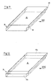
- FIG. 1 shows a first exemplary embodiment of a plate 10 made of insulating material according to the invention.
- the plate 10, which consists of mineral wool, for example, is formed in one piece and has a gradation or a step fold 20 on a long side 22, in which the gradation is carried out at right angles.
- the right longitudinal side in Fig. 1 22 is thus formed with protrusion 26 in the upper step area 28 with respect to the lower step area 30, while on the opposite (left) long side 22 'in the upper step area 28' a corresponding recess 26 'in relation to the lower step region 30 'is formed.
- This also clearly shows the front view of the corresponding broad side 24.
- FIG. 2 shows a cross-sectional view of part of a false ceiling 2, with the ceiling elements 4 including Plates 10 made of insulating material according to FIG. 1 are used.
- the plates 10 made of insulating material are each arranged in the lower step region 30, 30 'in ceiling plates 6, which are formed laterally with vertically upwardly extending flanges 8, which are each slightly higher on the right side in Fig. 2 than on the left side are and are each turned to the right.
- the right-hand edge 12 of a right-hand flange lies above the corresponding adjacent right-hand edge of the adjacent left-hand flange of an adjacent ceiling element 4.
- the heights of the upper and lower step areas 28, 28 'and 30, 30' on both sides different, that is, the upper step region 28 formed with protrusion 26 has a smaller thickness from the top of the ceiling slab than the recess of the upper step region 28 'in the region of the recess 26', so that there are nesting ceiling elements 4 between the nesting protruding projection 26 and recess 26 'adjacent plates 10 results in a slot in the two edges 12 of the flanges 8 adjacent ceiling plates 6 fit.
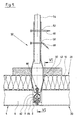
- FIG. 2 The part of the lower ceiling shown in FIG. 2 is shown with an adjacent wall 14, the attachment by means of C-shaped curved supports 16 and corresponding fastening elements 18 each being shown adjacent to the wall.
- the latter attachment makes use of the free space underneath, which is available through the overhang 26 adjacent to the wall.
- Fig. 3 is a sectional view taken along line III - III in Fig. 2, which illustrates the bracket on a wall 14 'perpendicular to the wall 14' by means of L-beams 16 '.
- a strip 40 of refractory insulating material is arranged along the wall 14 on the plate 10, directly abutting the wall.
- FIGS. 14 and 17 show a partial sectional view of the broad side of two adjacent ceiling elements 4 with vernier suspension 50.
- the ceiling elements 4 are not designed to be pivotable.
- two projections 9 or projecting strips are arranged one above the other.
- a recess 32 or 32' In the area of the suspension is provided on both sides on the long side 22 or 22 'of the plate 10, a recess 32 or 32' (see FIGS. 14 and 17) such that there is space for the attachment of the suspension and on the other hand little free Joints are formed.
- the vernier suspension 50 is of a type known per se.
- a holding rod 54 provided with transverse perforations 52 is arranged at the top of the ceiling or bare ceiling.
- a bracket-like mounting rail 56 is pushed from below over the support rod 54, which is also provided with transverse perforations 58, so that fixing by means of pins 68 and the like is possible at different distances from the ceiling.
- the bow-like fastening rail 56 is designed to be elongated, the base region 60 being bent inwards.
- a fastening clamp 62 is firmly held, while both clamping legs 64, 64 'at the lower end are inclined upwards and inwards and are then angled again at the outermost end so that they are firmly pressed in between the projections 9 rest against the flanges 8 between them, as a result of which the ceiling elements 4 are held.
- a strip 42 of refractory insulating material is arranged, which tightly delimits the bow-like fastening rail 56.
- FIG. 5 shows part of adjacent ceiling elements 4 with vernier suspension 50, the ceiling elements 4 being designed to be pivotable.
- the arrangement is essentially the same as in Fig. 4 so that it will not be described again.
- the recesses 32 are, however, narrower in the upper step area 28, while in the lower step area 30 more space is left around the clamping legs 64, so that the flanges 8 can be pivoted out of the fastening clamps 62 without problems and then the ceiling elements can be pivoted as a whole.
- FIG. 7 shows a partial longitudinal view of two pivotable adjacent ceiling elements 4 with vernier suspension 50. It is the overlapping of the upper step area 28 and the corresponding lower step area 30 'each adjacent plates illustrated.
- the arrow 36 indicates a slot 37, not shown in detail, in the plate 10, which is further illustrated in FIG. 13 and is intended for the suspension.
- FIG. 8 illustrates a partial cross-sectional view of two adjacent ceiling elements 4 similar to the illustration in FIG. 7, which are not designed to be pivotable.
- FIG. 6 shows a side view of part of a false ceiling 2, which illustrates the arrangement and pivoting of ceiling elements 4.
- the entire long side of a ceiling plate 6 and its attachment is shown.
- the long sides of the ceiling panels 6 are extended to the left in FIG. 6 by tabs 80 with cams 82.
- the ceiling panels 6 are by means of the cams 82 fixed movably in the mounting rail 56.
- the plates 10 are formed in the illustrated embodiment in the upper step area 28 with oblique long sides.
- the broad sides are provided with a bevel 38, in particular for pivoting the associated ceiling element.
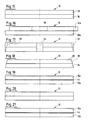
- the plate 10 shown in Fig. 10 consists of two individual plates 10a, 10b, which are arranged offset with respect to the longitudinal axis to form the step fold 20.
- the two plates 10a, 10b are connected to one another by a gypsum mass 44, which is provided as a heat-resistant, fire-resistant intermediate layer.
- the fourth exemplary embodiment of the plate 10 illustrated in FIG. 11 is again formed in one piece.
- the long side in the upper step region 28 is provided with a bevel 38, which is advantageously approximately 10 °.
- the configuration illustrated in FIG. 12 is similar Plate 10, which, however, is formed in two parts, ie as a composition of two staggered individual plates 10a and 10b, in which an aluminum foil is glued onto the top of the plate 10b or on the underside of the plate 10a by means of water glass.
- FIG. 13 shows a sixth exemplary embodiment of a plate 10 made of insulating material, which is formed from two individual plates 10a, 10b, which are arranged offset with respect to the longitudinal axis and with respect to the transverse axis.
- slots 37 are provided at the level of the lower step area on a long and long side for the passage of fastening elements in order to take account of the two-profile design on both sides.
- a plate 10 equipped with such slots 17 is illustrated in FIG. 7, a side wall of the ceiling element 6 being guided through the slot 37.
- the seventh and final exemplary embodiment of a plate 10 illustrated in FIG. 14 is formed in one piece and with a right-angled step fold and has recesses 32, 34 on the broad and long sides in order to provide space for fastening elements such as e.g. to form the fastening rails 56 and the fastening clamp 62 according to the exemplary embodiment of FIG. 5.
Landscapes
- Engineering & Computer Science (AREA)
- Architecture (AREA)
- Physics & Mathematics (AREA)
- Electromagnetism (AREA)
- Civil Engineering (AREA)
- Structural Engineering (AREA)
- Building Environments (AREA)
- Escalators And Moving Walkways (AREA)
- Magnetic Resonance Imaging Apparatus (AREA)
- Registering, Tensioning, Guiding Webs, And Rollers Therefor (AREA)
- Roof Covering Using Slabs Or Stiff Sheets (AREA)
Priority Applications (1)
| Application Number | Priority Date | Filing Date | Title |
|---|---|---|---|
| AT89104065T ATE76669T1 (de) | 1988-03-19 | 1989-03-08 | Deckenelement. |
Applications Claiming Priority (2)
| Application Number | Priority Date | Filing Date | Title |
|---|---|---|---|
| DE3809377 | 1988-03-19 | ||
| DE3809377A DE3809377A1 (de) | 1988-03-19 | 1988-03-19 | Deckenelement |
Publications (2)
| Publication Number | Publication Date |
|---|---|
| EP0334106A1 true EP0334106A1 (fr) | 1989-09-27 |
| EP0334106B1 EP0334106B1 (fr) | 1992-05-27 |
Family
ID=6350241
Family Applications (1)
| Application Number | Title | Priority Date | Filing Date |
|---|---|---|---|
| EP89104065A Expired - Lifetime EP0334106B1 (fr) | 1988-03-19 | 1989-03-08 | Elément de plafond |
Country Status (3)
| Country | Link |
|---|---|
| EP (1) | EP0334106B1 (fr) |
| AT (1) | ATE76669T1 (fr) |
| DE (2) | DE3809377A1 (fr) |
Cited By (2)
| Publication number | Priority date | Publication date | Assignee | Title |
|---|---|---|---|---|
| EP0695837A3 (fr) * | 1994-07-05 | 1997-05-02 | Schmitt Juergen | Faux plafond |
| WO2014135272A3 (fr) * | 2013-03-05 | 2014-10-30 | Saint-Gobain Isover | Système de protection contre les incendies pour bâtiments |
Families Citing this family (1)
| Publication number | Priority date | Publication date | Assignee | Title |
|---|---|---|---|---|
| DE10228002A1 (de) * | 2002-06-22 | 2004-01-15 | Deutsche Rockwool Mineralwoll Gmbh + Co Ohg | Gebäudeelement und Dämmstoffelement für ein Gebäudeelement |
Citations (9)
| Publication number | Priority date | Publication date | Assignee | Title |
|---|---|---|---|---|
| CH313328A (fr) * | 1953-12-07 | 1956-04-15 | Walter Jean Louis | Panneau préfabriqué pour plafond suspendu |
| FR1407103A (fr) * | 1964-05-22 | 1965-07-30 | Artex Products Mfg Ltd | Dalle de plafond |
| US3332194A (en) * | 1965-03-19 | 1967-07-25 | Johns Manville | Ceiling panel with concealing flange portion |
| DE1280528B (de) * | 1966-10-29 | 1968-10-17 | Friedrich Frueh | Verstellbarer Abhaenger fuer die Tragschienen einer Unterdecke od. dgl. |
| FR1575529A (fr) * | 1966-08-19 | 1969-07-25 | ||
| FR2118239A5 (fr) * | 1970-12-15 | 1972-07-28 | Prevost Lucienne | |
| DE2409555A1 (de) * | 1974-02-28 | 1975-09-04 | Zieringer Philipp Kg | Brandschutz-deckenanordnung |
| EP0092684A2 (fr) * | 1982-04-28 | 1983-11-02 | Wespanwerk Wenger AG | Panneau multicouche thermoisolant, inhibiteur de feu |
| DE3628332A1 (de) * | 1986-08-21 | 1988-02-25 | Gruenzweig & Hartmann Montage | Feuerhemmende unterdecke |
-
1988
- 1988-03-19 DE DE3809377A patent/DE3809377A1/de not_active Withdrawn
-
1989
- 1989-03-08 AT AT89104065T patent/ATE76669T1/de not_active IP Right Cessation
- 1989-03-08 DE DE8989104065T patent/DE58901517D1/de not_active Expired - Lifetime
- 1989-03-08 EP EP89104065A patent/EP0334106B1/fr not_active Expired - Lifetime
Patent Citations (9)
| Publication number | Priority date | Publication date | Assignee | Title |
|---|---|---|---|---|
| CH313328A (fr) * | 1953-12-07 | 1956-04-15 | Walter Jean Louis | Panneau préfabriqué pour plafond suspendu |
| FR1407103A (fr) * | 1964-05-22 | 1965-07-30 | Artex Products Mfg Ltd | Dalle de plafond |
| US3332194A (en) * | 1965-03-19 | 1967-07-25 | Johns Manville | Ceiling panel with concealing flange portion |
| FR1575529A (fr) * | 1966-08-19 | 1969-07-25 | ||
| DE1280528B (de) * | 1966-10-29 | 1968-10-17 | Friedrich Frueh | Verstellbarer Abhaenger fuer die Tragschienen einer Unterdecke od. dgl. |
| FR2118239A5 (fr) * | 1970-12-15 | 1972-07-28 | Prevost Lucienne | |
| DE2409555A1 (de) * | 1974-02-28 | 1975-09-04 | Zieringer Philipp Kg | Brandschutz-deckenanordnung |
| EP0092684A2 (fr) * | 1982-04-28 | 1983-11-02 | Wespanwerk Wenger AG | Panneau multicouche thermoisolant, inhibiteur de feu |
| DE3628332A1 (de) * | 1986-08-21 | 1988-02-25 | Gruenzweig & Hartmann Montage | Feuerhemmende unterdecke |
Cited By (2)
| Publication number | Priority date | Publication date | Assignee | Title |
|---|---|---|---|---|
| EP0695837A3 (fr) * | 1994-07-05 | 1997-05-02 | Schmitt Juergen | Faux plafond |
| WO2014135272A3 (fr) * | 2013-03-05 | 2014-10-30 | Saint-Gobain Isover | Système de protection contre les incendies pour bâtiments |
Also Published As
| Publication number | Publication date |
|---|---|
| EP0334106B1 (fr) | 1992-05-27 |
| DE58901517D1 (de) | 1992-07-02 |
| ATE76669T1 (de) | 1992-06-15 |
| DE3809377A1 (de) | 1989-09-28 |
Similar Documents
| Publication | Publication Date | Title |
|---|---|---|
| CH623097A5 (fr) | ||
| EP0074490A2 (fr) | Sol avec chauffage intégré par eau chaude | |
| DE3815140A1 (de) | Fugenschalung fuer glasbauelemente, welche aus mehreren glaselementen, insbesondere glasbausteinen bestehen | |
| EP0018006B1 (fr) | Isolation pour le toit ou le mur d'un bâtiment et procédé pour son montage | |
| DE69701032T2 (de) | Verfahren für das Anbringen einer Isolation | |
| EP0334106B1 (fr) | Elément de plafond | |
| DE2930044A1 (de) | Bauteil. | |
| DE2657136A1 (de) | Verfahren zum bau einer waermedaemmenden mauer sowie baustein dafuer | |
| DE4036735A1 (de) | Deckenelement | |
| WO2001096702A1 (fr) | Element de construction et utilisation d'un support, et procede de fabrication d'un element de façade | |
| DE3136450C2 (fr) | ||
| DE3214291A1 (de) | Brandschutzplatte und verfahren zu deren herstellung | |
| DE8803779U1 (de) | Deckenelement | |
| EP0548531B1 (fr) | Fenêtre basculante d'un toit vitré ou d'un mur vitré | |
| DE2349125A1 (de) | Zwischenwand zur trennung von raeumen | |
| CH658284A5 (de) | Plattenfoermiges bauelement fuer die mantelbetonbauweise. | |
| EP0861963B1 (fr) | Vitrage pare-feu | |
| DE3215706A1 (de) | Bauelement | |
| DE7221705U (de) | Plattenartiges Bauteil | |
| CH655346A5 (de) | Tragendes bauelement fuer decken oder daecher. | |
| DE2718839A1 (de) | Feuerfester kanal | |
| DE816143C (de) | Loesbare Befestigung von plattenfoermigen Innenraumverkleidungen an gebaeudefesten Teilen | |
| DE4036859C2 (de) | Trennwand | |
| AT397126B (de) | Torblatt für brandschutztore | |
| EP0166012B1 (fr) | Fixation pour un revêtement de bâtiment ventilé en arrière |
Legal Events
| Date | Code | Title | Description |
|---|---|---|---|
| PUAI | Public reference made under article 153(3) epc to a published international application that has entered the european phase |
Free format text: ORIGINAL CODE: 0009012 |
|
| AK | Designated contracting states |
Kind code of ref document: A1 Designated state(s): AT BE CH DE FR GB LI NL |
|
| 17P | Request for examination filed |
Effective date: 19900223 |
|
| 17Q | First examination report despatched |
Effective date: 19910219 |
|
| GRAA | (expected) grant |
Free format text: ORIGINAL CODE: 0009210 |
|
| AK | Designated contracting states |
Kind code of ref document: B1 Designated state(s): AT BE CH DE FR GB LI NL |
|
| REF | Corresponds to: |
Ref document number: 76669 Country of ref document: AT Date of ref document: 19920615 Kind code of ref document: T |
|
| REF | Corresponds to: |
Ref document number: 58901517 Country of ref document: DE Date of ref document: 19920702 |
|
| ET | Fr: translation filed | ||
| GBT | Gb: translation of ep patent filed (gb section 77(6)(a)/1977) | ||
| PLBE | No opposition filed within time limit |
Free format text: ORIGINAL CODE: 0009261 |
|
| STAA | Information on the status of an ep patent application or granted ep patent |
Free format text: STATUS: NO OPPOSITION FILED WITHIN TIME LIMIT |
|
| 26N | No opposition filed | ||
| REG | Reference to a national code |
Ref country code: GB Ref legal event code: IF02 |
|
| PGFP | Annual fee paid to national office [announced via postgrant information from national office to epo] |
Ref country code: DE Payment date: 20040507 Year of fee payment: 16 |
|
| PGFP | Annual fee paid to national office [announced via postgrant information from national office to epo] |
Ref country code: CH Payment date: 20040623 Year of fee payment: 16 |
|
| PGFP | Annual fee paid to national office [announced via postgrant information from national office to epo] |
Ref country code: GB Payment date: 20050221 Year of fee payment: 17 |
|
| PGFP | Annual fee paid to national office [announced via postgrant information from national office to epo] |
Ref country code: BE Payment date: 20050309 Year of fee payment: 17 |
|
| PGFP | Annual fee paid to national office [announced via postgrant information from national office to epo] |
Ref country code: FR Payment date: 20050322 Year of fee payment: 17 |
|
| PG25 | Lapsed in a contracting state [announced via postgrant information from national office to epo] |
Ref country code: LI Free format text: LAPSE BECAUSE OF NON-PAYMENT OF DUE FEES Effective date: 20050331 Ref country code: CH Free format text: LAPSE BECAUSE OF NON-PAYMENT OF DUE FEES Effective date: 20050331 |
|
| PGFP | Annual fee paid to national office [announced via postgrant information from national office to epo] |
Ref country code: NL Payment date: 20050331 Year of fee payment: 17 Ref country code: AT Payment date: 20050331 Year of fee payment: 17 |
|
| PG25 | Lapsed in a contracting state [announced via postgrant information from national office to epo] |
Ref country code: DE Free format text: LAPSE BECAUSE OF NON-PAYMENT OF DUE FEES Effective date: 20051001 |
|
| REG | Reference to a national code |
Ref country code: CH Ref legal event code: PL |
|
| PG25 | Lapsed in a contracting state [announced via postgrant information from national office to epo] |
Ref country code: GB Free format text: LAPSE BECAUSE OF NON-PAYMENT OF DUE FEES Effective date: 20060308 Ref country code: AT Free format text: LAPSE BECAUSE OF NON-PAYMENT OF DUE FEES Effective date: 20060308 |
|
| PG25 | Lapsed in a contracting state [announced via postgrant information from national office to epo] |
Ref country code: BE Free format text: LAPSE BECAUSE OF NON-PAYMENT OF DUE FEES Effective date: 20060331 |
|
| PG25 | Lapsed in a contracting state [announced via postgrant information from national office to epo] |
Ref country code: NL Free format text: LAPSE BECAUSE OF NON-PAYMENT OF DUE FEES Effective date: 20061001 |
|
| GBPC | Gb: european patent ceased through non-payment of renewal fee |
Effective date: 20060308 |
|
| NLV4 | Nl: lapsed or anulled due to non-payment of the annual fee |
Effective date: 20061001 |
|
| REG | Reference to a national code |
Ref country code: FR Ref legal event code: ST Effective date: 20061130 |
|
| BERE | Be: lapsed |
Owner name: *SCHMITT JURGEN Effective date: 20060331 |
|
| PG25 | Lapsed in a contracting state [announced via postgrant information from national office to epo] |
Ref country code: FR Free format text: LAPSE BECAUSE OF NON-PAYMENT OF DUE FEES Effective date: 20060331 |