EP0334202A2 - Stoff- und/oder Wärmetauscher - Google Patents
Stoff- und/oder Wärmetauscher Download PDFInfo
- Publication number
- EP0334202A2 EP0334202A2 EP89104676A EP89104676A EP0334202A2 EP 0334202 A2 EP0334202 A2 EP 0334202A2 EP 89104676 A EP89104676 A EP 89104676A EP 89104676 A EP89104676 A EP 89104676A EP 0334202 A2 EP0334202 A2 EP 0334202A2
- Authority
- EP
- European Patent Office
- Prior art keywords
- housing
- tube
- tube sheet
- tubes
- seal
- Prior art date
- Legal status (The legal status is an assumption and is not a legal conclusion. Google has not performed a legal analysis and makes no representation as to the accuracy of the status listed.)
- Granted
Links
Images
Classifications
-
- F—MECHANICAL ENGINEERING; LIGHTING; HEATING; WEAPONS; BLASTING
- F28—HEAT EXCHANGE IN GENERAL
- F28F—DETAILS OF HEAT-EXCHANGE AND HEAT-TRANSFER APPARATUS, OF GENERAL APPLICATION
- F28F21/00—Constructions of heat-exchange apparatus characterised by the selection of particular materials
-
- B—PERFORMING OPERATIONS; TRANSPORTING
- B01—PHYSICAL OR CHEMICAL PROCESSES OR APPARATUS IN GENERAL
- B01D—SEPARATION
- B01D63/00—Apparatus in general for separation processes using semi-permeable membranes
- B01D63/06—Tubular membrane modules
- B01D63/061—Manufacturing thereof
-
- B—PERFORMING OPERATIONS; TRANSPORTING
- B01—PHYSICAL OR CHEMICAL PROCESSES OR APPARATUS IN GENERAL
- B01D—SEPARATION
- B01D65/00—Accessories or auxiliary operations, in general, for separation processes or apparatus using semi-permeable membranes
-
- B—PERFORMING OPERATIONS; TRANSPORTING
- B29—WORKING OF PLASTICS; WORKING OF SUBSTANCES IN A PLASTIC STATE IN GENERAL
- B29C—SHAPING OR JOINING OF PLASTICS; SHAPING OF MATERIAL IN A PLASTIC STATE, NOT OTHERWISE PROVIDED FOR; AFTER-TREATMENT OF THE SHAPED PRODUCTS, e.g. REPAIRING
- B29C70/00—Shaping composites, i.e. plastics material comprising reinforcements, fillers or preformed parts, e.g. inserts
- B29C70/68—Shaping composites, i.e. plastics material comprising reinforcements, fillers or preformed parts, e.g. inserts by incorporating or moulding on preformed parts, e.g. inserts or layers, e.g. foam blocks
- B29C70/84—Shaping composites, i.e. plastics material comprising reinforcements, fillers or preformed parts, e.g. inserts by incorporating or moulding on preformed parts, e.g. inserts or layers, e.g. foam blocks by moulding material on preformed parts to be joined
- B29C70/845—Shaping composites, i.e. plastics material comprising reinforcements, fillers or preformed parts, e.g. inserts by incorporating or moulding on preformed parts, e.g. inserts or layers, e.g. foam blocks by moulding material on preformed parts to be joined by moulding material on a relative small portion of the preformed parts
-
- F—MECHANICAL ENGINEERING; LIGHTING; HEATING; WEAPONS; BLASTING
- F28—HEAT EXCHANGE IN GENERAL
- F28F—DETAILS OF HEAT-EXCHANGE AND HEAT-TRANSFER APPARATUS, OF GENERAL APPLICATION
- F28F21/00—Constructions of heat-exchange apparatus characterised by the selection of particular materials
- F28F21/06—Constructions of heat-exchange apparatus characterised by the selection of particular materials of plastics material
- F28F21/067—Details
-
- F—MECHANICAL ENGINEERING; LIGHTING; HEATING; WEAPONS; BLASTING
- F28—HEAT EXCHANGE IN GENERAL
- F28F—DETAILS OF HEAT-EXCHANGE AND HEAT-TRANSFER APPARATUS, OF GENERAL APPLICATION
- F28F9/00—Casings; Header boxes; Auxiliary supports for elements; Auxiliary members within casings
- F28F9/02—Header boxes; End plates
- F28F9/0219—Arrangements for sealing end plates into casing or header box; Header box sub-elements
-
- B—PERFORMING OPERATIONS; TRANSPORTING
- B01—PHYSICAL OR CHEMICAL PROCESSES OR APPARATUS IN GENERAL
- B01D—SEPARATION
- B01D2313/00—Details relating to membrane modules or apparatus
- B01D2313/04—Specific sealing means
-
- B—PERFORMING OPERATIONS; TRANSPORTING
- B01—PHYSICAL OR CHEMICAL PROCESSES OR APPARATUS IN GENERAL
- B01D—SEPARATION
- B01D2313/00—Details relating to membrane modules or apparatus
- B01D2313/22—Cooling or heating elements
- B01D2313/221—Heat exchangers
Definitions
- the invention describes a material and / or heat exchanger consisting of a housing, at least two tube plates and a plurality of tubes, the ends of the tubes being connected to the tube plates, and the tube plates being designed such that they are partially inside the housing provided openings and partially outside the housing, the housing openings are arranged covering.
- Substance exchangers of this type are known from DE-AS 25 54 062.
- the tube sheets have the advantage of covering the housing openings that there are sealing surfaces between the cover and the housing opening, which - if necessary by inserting sealing rings - enable a good seal by bracing the tube plates with the housing.
- Such training is only possible if the tube sheets are manufactured separately.
- the pipes When installing in the housing, the pipes must be threaded into holes provided in the tube sheet and connected to the tube sheet. Therefore, the production of such mass exchangers is very complex.
- a material and / or heat exchanger of the type mentioned which is characterized in that a seal is arranged between the tube sheet and the housing inside and outside the housing openings, and that the tube sheet has been produced by casting on the housing.
- the arrangement of the seal inside and outside the housing openings reliably prevents the potting compound from being able to penetrate between the seal and the housing during manufacture.
- the reduction in volume when solidifying no longer plays a role, since the seal can surprisingly compensate for the unevenness in the tube sheet caused by the shrinkage. By tightening the tube sheet with the housing, a good seal is achieved in the overlap area.
- the seal be made of an elastic material.
- the seal is pressed together during casting, and expands again when the sealing compound solidifies, so that the space between the housing and the solid tube sheet is filled with the seal.
- tubes are also to be understood as hollow threads and tubes with a plurality of continuous cavities.
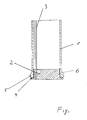
- the invention is illustrated by the following figure.
- the housing is denoted by 1, the tube sheet by 2 and the tubes by 3.
- the tubes 3 are embedded in the casting compound, which is arranged partially inside the housing opening (in area 5) and partially outside the housing, covering the housing opening (area 4) and forming the tube sheet.
- the seal 6 is arranged inside (region 5) and outside (region 4) the housing opening.
Landscapes
- Engineering & Computer Science (AREA)
- Mechanical Engineering (AREA)
- Physics & Mathematics (AREA)
- Thermal Sciences (AREA)
- General Engineering & Computer Science (AREA)
- Chemical & Material Sciences (AREA)
- Chemical Kinetics & Catalysis (AREA)
- Composite Materials (AREA)
- Manufacturing & Machinery (AREA)
- Heat-Exchange Devices With Radiators And Conduit Assemblies (AREA)
- Separation Using Semi-Permeable Membranes (AREA)
Abstract
Description
- Die Erfindung beschreibt einen Stoff- und/oder Wärmetauscher, bestehend aus einem Gehäuse, mindestens zwei Rohrböden und einer Vielzahl von Rohren, wobei die Enden der Rohre mit den Rohrböden verbunden sind, und die Rohrböden derart ausgebildet sind, daß sie teilweise innerhalb von im Gehäuse vorgesehenen Öffnungen und teilweise außerhalb des Gehäuses, die Gehäuseöffnungen überdeckend angeordnet sind.
- Stoffaustauscher dieser Art sind aus der DE-AS 25 54 062 bekannt. Hierbei haben die Rohrböden durch die Überdeckung der Gehäuseöffnungen den Vorteil, daß zwischen der Überdeckung und der Gehäuseöffnung Dichtflächen vorhanden sind, die - gegebenenfalls durch Einlegen von Dichtringen - durch Verspannung von den Rohrböden mit dem Gehäuse eine gute Abdichtung ermöglichen. Eine derartige Ausbildung ist aber nur möglich, wenn die Rohrböden getrennt hergestellt werden. Beim Einbau in das Gehäuse müssen die Rohre in im Rohrboden vorgesehene Löcher eingefädelt und mit dem Rohrboden verbunden werden. Deshalb ist die Herstellung solcher Stofftauscher sehr aufwendig.
- Es gibt auch Stoff- und/oder Wärmeaustauscher, bei denen die Rohrböden beim Zusammenbau hergestellt werden, indem eine Vergußmasse in die Gehäuseöffnungen eingegossen wird, in welcher die Rohrenden eingebettet werden, und welche anschließend fest wird. Hierzu werden selbsthärtende Gußmassen oder thermoplastische Schmelzen (Ep-A 168 558) eingesetzt. Bei dieser Art der Herstellung, die weniger aufwendig ist, lassen sich zwar auch Rohrböden herstellen, die die Gehäuseöffnungen überdecken, doch hat sich herausgestellt, daß infolge der unvermeidlichen Volumenverringerung der Gußmasse beim Festwerden eine Ablösung der Gußmasse vom Gehäuse erfolgt. Eine Abdichtung über Verspannung ist bei dieser Herstellart nicht mehr gewährleistet, weil durch die Ablösung des Rohrbodens von dem Gehäuse eine unebene Oberfläche des Rohrbodens entsteht. Stoff- und/oder Wärmetauscher der eingangs genannten Art mit einer großen Anzahl von Rohren sind deswegen als auf diese Weise nicht herstellbar angesehen worden.
- Es ist deshalb Aufgabe der vorliegenden Erfindung, einen Stoff- und/oder Wärmetauscher der eingangs genannten Art zur Verfügung zu stellen, welcher mit geringem Aufwand hergestellt werden kann, und gleichzeitig eine Dichtigkeit zwischen Rohrboden und Gehäuse aufweist, wie sie bisher nur über sehr aufwendige Herstellverfahren gewährleistet werden konnte.
- Diese Aufgabe wird gelöst durch einen Stoff- und/oder Wärmetauscher der eingangs genannten Art, welcher sich dadurch auszeichnet, daß zwischen Rohrboden und Gehäuse innerhalb und außerhalb der Gehäuseöffnungen eine Dichtung angeordnet ist, und daß der Rohrboden über Gießen am Gehäuse hergestellt worden ist.
- Durch die Anordnung der Dichtung innerhalb und außerhalb der Gehäuseöffnungen wird bei der Herstellung sicher verhindert, daß die Vergußmasse zwischen Dichtung und Gehäusedringen kann. Die Volumenverringerung beim Festwerden spielt keine Rolle mehr, da durch die Dichtung überraschenderweise die durch den Schwund entstehenden Unebenheiten am Rohrboden ausgeglichen werden können. Durch Verspannen des Rohrbodens mit dem Gehäuse wird im Überdeckungsbereich eine gute Abdichtung erreicht.
- Bei Gießverfahren, die unter Druck ausgeführt werden, wie beispielsweise Schleuderguß, Vergießen durch Zentrifugieren oder Spriitzguß, empfiehlt es sich, daß die Dichtung aus einem elastischen Material besteht. Hierbei wird beim Gießen die Dichtung zusammengepreßt, und dehnt sich beim Festwerden der Vergußmasse wieder aus, so daß der Raum zwischen Gehäuse und dem festgewordenen Rohrboden mit der Dichtung ausgefüllt ist.
- Es ist erkennbar, wenn der Rohrboden über Gießen am Gehäuse hergestellt worden ist, weil bei diesem Herstellverfahren die Rohre nicht ganz gleichmäßig angeordnet sind und weil infolge der Überdeckung der Gehäuseöffnung durch den Rohrboden von außen ein vorheriges Herstellen ausgeschlossen ist.
- Im Sinne der vorliegenden Erfindung sind unter Rohren auch Hohlfäden und Rohre mit mehreren durchgehenden Hohlräumen zu verstehen.
- Die Erfindung wird anhand der nachfolgenden Figur näher erläutert.
- In der Figur ist ein Ausschnitt aus einem erfindungsgemäßen Stoff- und/oder Wärmetauscher dargestellt. Hierbei ist das Gehäuse mit 1, der Rohrboden mit 2 und die Rohre mit 3 bezeichnet. Der Übersichtlichkeit halber ist in der Figur nur eine Gehäuseöffnung mit einem Rohrboden 2 und ein Ausschnitt aus dem Gehäuse 1 sowie lediglich zwei Rohre 3 dargestellt. Die Rohre 3 sind in der Vergußmasse eingebettet, die teilweise innerhalb der Gehäuseöffnung (im Bereich 5) und teilweise außerhalb des Gehäuses, die Gehäuseöffnung überdeckend (Bereich 4) angeordnet ist und den Rohrboden bildet. Zwischen Rohrboden und Gehäuse ist die Dichtung 6 innerhalb (Bereich 5) und außerhalb (Bereich 4) der Gehäuseöffnung angeordnet.
Claims (2)
dadurch gekennzeichnet,
daß zwischen Rohrboden und Gehäuse innerhalb und außerhalb der Gehäuseöffnungen eine Dichtung angeordnet ist, und daß der Rohrboden über Gießen am Gehäuse hergestellt ist.
dadurch gekennzeichnet,
daß die Dichtung aus einem elastischen Material besteht.
Applications Claiming Priority (2)
| Application Number | Priority Date | Filing Date | Title |
|---|---|---|---|
| DE3809557A DE3809557A1 (de) | 1988-03-22 | 1988-03-22 | Stoff- und/oder waermetauscher |
| DE3809557 | 1988-03-22 |
Publications (3)
| Publication Number | Publication Date |
|---|---|
| EP0334202A2 true EP0334202A2 (de) | 1989-09-27 |
| EP0334202A3 EP0334202A3 (en) | 1990-01-17 |
| EP0334202B1 EP0334202B1 (de) | 1992-07-15 |
Family
ID=6350341
Family Applications (1)
| Application Number | Title | Priority Date | Filing Date |
|---|---|---|---|
| EP89104676A Expired - Lifetime EP0334202B1 (de) | 1988-03-22 | 1989-03-16 | Stoff- und/oder Wärmetauscher |
Country Status (6)
| Country | Link |
|---|---|
| US (1) | US4932470A (de) |
| EP (1) | EP0334202B1 (de) |
| JP (1) | JPH029422A (de) |
| AU (1) | AU609270B2 (de) |
| DE (2) | DE3809557A1 (de) |
| ES (1) | ES2033033T3 (de) |
Cited By (2)
| Publication number | Priority date | Publication date | Assignee | Title |
|---|---|---|---|---|
| FR2699424A1 (fr) * | 1992-12-21 | 1994-06-24 | Dumez Lyonnaise Eaux | Module de filtration à fibres creuses et son procédé de fabrication. |
| EP1422489A3 (de) * | 2002-11-22 | 2010-03-31 | GEA LUFTKÜHLER GmbH | Wärmeaustauscher |
Families Citing this family (1)
| Publication number | Priority date | Publication date | Assignee | Title |
|---|---|---|---|---|
| EP3925691A1 (de) * | 2020-06-18 | 2021-12-22 | Gambro Lundia AB | Diffusionsvorrichtung |
Family Cites Families (11)
| Publication number | Priority date | Publication date | Assignee | Title |
|---|---|---|---|---|
| US2170181A (en) * | 1937-06-11 | 1939-08-22 | Morris C Allen | Elastic pipe joint |
| US3415315A (en) * | 1966-06-29 | 1968-12-10 | Borg Warner | Heat exchanger |
| US3832830A (en) * | 1972-09-18 | 1974-09-03 | Du Pont | Permeation separation device |
| CH558514A (de) * | 1972-11-28 | 1975-01-31 | Sulzer Ag | Vorrichtung zum durchfuehren eines rohrbuendels durch eine behaelterwand. |
| DE2554062C3 (de) * | 1974-12-04 | 1980-12-18 | Asahi Kasei Kogyo K.K., Osaka (Japan) | Dialyseneinheiten |
| SE393535B (sv) * | 1975-09-11 | 1977-05-16 | Gambro Ab | Anordning for diffusion av emnen mellan tva fluider via semipermeabla membran |
| US4031012A (en) * | 1975-09-17 | 1977-06-21 | Gics Pharmaceuticals, Inc. | Separatory apparatus |
| DE3016636A1 (de) * | 1980-04-30 | 1981-11-05 | Boehringer Mannheim Gmbh, 6800 Mannheim | Stoffaustauschmodul, insbesondere fuer medizinische anwendungen |
| US4557322A (en) * | 1984-07-09 | 1985-12-10 | Kennedy Tank & Manufacturing Company, Inc. | Heat exchanger closure system |
| DE3575695D1 (de) * | 1984-07-18 | 1990-03-08 | Akzo Gmbh | Verfahren und vorrichtung zum herstellen von waerme- und/oder stoffaustauschern, die rohre enthalten. |
| JPS6163240U (de) * | 1984-09-29 | 1986-04-28 |
-
1988
- 1988-03-22 DE DE3809557A patent/DE3809557A1/de not_active Withdrawn
-
1989
- 1989-03-16 ES ES198989104676T patent/ES2033033T3/es not_active Expired - Lifetime
- 1989-03-16 DE DE8989104676T patent/DE58901826D1/de not_active Expired - Lifetime
- 1989-03-16 EP EP89104676A patent/EP0334202B1/de not_active Expired - Lifetime
- 1989-03-20 US US07/325,980 patent/US4932470A/en not_active Expired - Fee Related
- 1989-03-20 AU AU31510/89A patent/AU609270B2/en not_active Ceased
- 1989-03-22 JP JP1067746A patent/JPH029422A/ja active Pending
Cited By (2)
| Publication number | Priority date | Publication date | Assignee | Title |
|---|---|---|---|---|
| FR2699424A1 (fr) * | 1992-12-21 | 1994-06-24 | Dumez Lyonnaise Eaux | Module de filtration à fibres creuses et son procédé de fabrication. |
| EP1422489A3 (de) * | 2002-11-22 | 2010-03-31 | GEA LUFTKÜHLER GmbH | Wärmeaustauscher |
Also Published As
| Publication number | Publication date |
|---|---|
| AU609270B2 (en) | 1991-04-26 |
| EP0334202A3 (en) | 1990-01-17 |
| DE58901826D1 (de) | 1992-08-20 |
| US4932470A (en) | 1990-06-12 |
| EP0334202B1 (de) | 1992-07-15 |
| ES2033033T3 (es) | 1993-03-01 |
| JPH029422A (ja) | 1990-01-12 |
| DE3809557A1 (de) | 1989-10-12 |
| AU3151089A (en) | 1989-09-28 |
Similar Documents
| Publication | Publication Date | Title |
|---|---|---|
| DE3023681C2 (de) | ||
| DE3231861C2 (de) | ||
| DE10163282B4 (de) | Zahnstangengetriebe, insbesondere Zahnstangenlenkgetriebe sowie Verfahren zu dessen Erstellung | |
| DE2707134C2 (de) | ||
| DE60016796T2 (de) | Verfahren zur herstellung von kunststoff-rotoren | |
| EP0343347A1 (de) | Werkzeugrevolver | |
| DE2905001C2 (de) | Rohrbündelwärmetauscher | |
| DE2353334A1 (de) | Verfahren zum herstellen von batterieanschlusspolen aus metall und nach dem verfahren hergestellter anschlusspol | |
| EP0334202A2 (de) | Stoff- und/oder Wärmetauscher | |
| EP0233980B1 (de) | Membranfilterplatte für eine Filterpresse oder dergleichen mit Stütznocken | |
| CH626265A5 (de) | ||
| DE4110437C2 (de) | Heizbalghalterung einer Reifenvulkanisiermaschine | |
| EP0425850B1 (de) | Schneckenwellenmaschine mit zusammengesetztem Gehäuse | |
| DE2317828C3 (de) | Flacher Hohlkörper, insbesondere Plattenheizkörper, mit angeschweißten Fittings | |
| DE3324833C2 (de) | Haltevorrichtung für rechteckige Düsenplatten | |
| DE3604963A1 (de) | Einsatz zum unterteilen einer giessform | |
| EP0156863A1 (de) | Verfahren zum herstellen eines wärmetauschers | |
| DE10259900B4 (de) | Filterelement, Verfahren zu dessen Herstellung und Verwendung des Filterelements | |
| EP0570700B1 (de) | Verfahren zur Herstellung eines Zahnrades einer Innenzahnradpumpe | |
| DE3445351A1 (de) | Wasserenthaertungsanlage | |
| DE4215472C1 (en) | Welt filter for cleaning plastic melts - having sieve plate cut=out along the side which can hold filters in the form of ring members | |
| EP0015536A1 (de) | Verfahren und Vorrichtung zum Herstellen von wärmeisolierenden Verbundprofilen sowie nach dem Verfahren hergestelltes Verbundprofil | |
| DE3836729A1 (de) | Membranfilterplatte und verfahren zum befestigen der membrane | |
| DE2705560C3 (de) | Filter für Polymerschmelzen und Polymerlösungen | |
| DE3825313A1 (de) | Vorrichtung fuer die befestigung von druckschlaeuchen in anschlussbohrungen |
Legal Events
| Date | Code | Title | Description |
|---|---|---|---|
| PUAI | Public reference made under article 153(3) epc to a published international application that has entered the european phase |
Free format text: ORIGINAL CODE: 0009012 |
|
| AK | Designated contracting states |
Kind code of ref document: A2 Designated state(s): AT BE CH DE ES FR GB GR IT LI LU NL SE |
|
| PUAL | Search report despatched |
Free format text: ORIGINAL CODE: 0009013 |
|
| AK | Designated contracting states |
Kind code of ref document: A3 Designated state(s): AT BE CH DE ES FR GB GR IT LI LU NL SE |
|
| 17P | Request for examination filed |
Effective date: 19900129 |
|
| 17Q | First examination report despatched |
Effective date: 19911008 |
|
| RBV | Designated contracting states (corrected) |
Designated state(s): DE ES FR GB IT NL |
|
| GRAA | (expected) grant |
Free format text: ORIGINAL CODE: 0009210 |
|
| AK | Designated contracting states |
Kind code of ref document: B1 Designated state(s): DE ES FR GB IT NL |
|
| ITF | It: translation for a ep patent filed | ||
| GBT | Gb: translation of ep patent filed (gb section 77(6)(a)/1977) | ||
| ET | Fr: translation filed | ||
| REF | Corresponds to: |
Ref document number: 58901826 Country of ref document: DE Date of ref document: 19920820 |
|
| ET1 | Fr: translation filed ** revision of the translation of the patent or the claims | ||
| REG | Reference to a national code |
Ref country code: ES Ref legal event code: FG2A Ref document number: 2033033 Country of ref document: ES Kind code of ref document: T3 |
|
| PLBE | No opposition filed within time limit |
Free format text: ORIGINAL CODE: 0009261 |
|
| STAA | Information on the status of an ep patent application or granted ep patent |
Free format text: STATUS: NO OPPOSITION FILED WITHIN TIME LIMIT |
|
| 26N | No opposition filed | ||
| PGFP | Annual fee paid to national office [announced via postgrant information from national office to epo] |
Ref country code: FR Payment date: 19940126 Year of fee payment: 6 |
|
| PGFP | Annual fee paid to national office [announced via postgrant information from national office to epo] |
Ref country code: GB Payment date: 19940210 Year of fee payment: 6 Ref country code: DE Payment date: 19940210 Year of fee payment: 6 |
|
| PGFP | Annual fee paid to national office [announced via postgrant information from national office to epo] |
Ref country code: ES Payment date: 19940225 Year of fee payment: 6 |
|
| PGFP | Annual fee paid to national office [announced via postgrant information from national office to epo] |
Ref country code: NL Payment date: 19940331 Year of fee payment: 6 |
|
| PG25 | Lapsed in a contracting state [announced via postgrant information from national office to epo] |
Ref country code: GB Effective date: 19950316 |
|
| PG25 | Lapsed in a contracting state [announced via postgrant information from national office to epo] |
Ref country code: ES Free format text: LAPSE BECAUSE OF NON-PAYMENT OF DUE FEES Effective date: 19950317 |
|
| PG25 | Lapsed in a contracting state [announced via postgrant information from national office to epo] |
Ref country code: NL Effective date: 19951001 |
|
| GBPC | Gb: european patent ceased through non-payment of renewal fee |
Effective date: 19950316 |
|
| PG25 | Lapsed in a contracting state [announced via postgrant information from national office to epo] |
Ref country code: FR Free format text: LAPSE BECAUSE OF NON-PAYMENT OF DUE FEES Effective date: 19951130 |
|
| NLV4 | Nl: lapsed or anulled due to non-payment of the annual fee |
Effective date: 19951001 |
|
| PG25 | Lapsed in a contracting state [announced via postgrant information from national office to epo] |
Ref country code: DE Effective date: 19951201 |
|
| REG | Reference to a national code |
Ref country code: FR Ref legal event code: ST |
|
| REG | Reference to a national code |
Ref country code: ES Ref legal event code: FD2A Effective date: 19990301 |
|
| PG25 | Lapsed in a contracting state [announced via postgrant information from national office to epo] |
Ref country code: IT Free format text: LAPSE BECAUSE OF NON-PAYMENT OF DUE FEES;WARNING: LAPSES OF ITALIAN PATENTS WITH EFFECTIVE DATE BEFORE 2007 MAY HAVE OCCURRED AT ANY TIME BEFORE 2007. THE CORRECT EFFECTIVE DATE MAY BE DIFFERENT FROM THE ONE RECORDED. Effective date: 20050316 |