EP0334216A2 - Verfahren und Vorrichtung zum Sterilisieren von Deckeln - Google Patents
Verfahren und Vorrichtung zum Sterilisieren von Deckeln Download PDFInfo
- Publication number
- EP0334216A2 EP0334216A2 EP89104748A EP89104748A EP0334216A2 EP 0334216 A2 EP0334216 A2 EP 0334216A2 EP 89104748 A EP89104748 A EP 89104748A EP 89104748 A EP89104748 A EP 89104748A EP 0334216 A2 EP0334216 A2 EP 0334216A2
- Authority
- EP
- European Patent Office
- Prior art keywords
- lid
- container
- sucking disk
- room
- mouth
- Prior art date
- Legal status (The legal status is an assumption and is not a legal conclusion. Google has not performed a legal analysis and makes no representation as to the accuracy of the status listed.)
- Granted
Links
Images








Classifications
-
- B—PERFORMING OPERATIONS; TRANSPORTING
- B65—CONVEYING; PACKING; STORING; HANDLING THIN OR FILAMENTARY MATERIAL
- B65B—MACHINES, APPARATUS OR DEVICES FOR, OR METHODS OF, PACKAGING ARTICLES OR MATERIALS; UNPACKING
- B65B7/00—Closing containers or receptacles after filling
- B65B7/16—Closing semi-rigid or rigid containers or receptacles not deformed by, or not taking-up shape of, contents, e.g. boxes or cartons
- B65B7/28—Closing semi-rigid or rigid containers or receptacles not deformed by, or not taking-up shape of, contents, e.g. boxes or cartons by applying separate preformed closures, e.g. lids, covers
- B65B7/2807—Feeding closures
-
- B—PERFORMING OPERATIONS; TRANSPORTING
- B65—CONVEYING; PACKING; STORING; HANDLING THIN OR FILAMENTARY MATERIAL
- B65B—MACHINES, APPARATUS OR DEVICES FOR, OR METHODS OF, PACKAGING ARTICLES OR MATERIALS; UNPACKING
- B65B55/00—Preserving, protecting or purifying packages or package contents in association with packaging
- B65B55/02—Sterilising, e.g. of complete packages
- B65B55/04—Sterilising wrappers or receptacles prior to, or during, packaging
-
- B—PERFORMING OPERATIONS; TRANSPORTING
- B65—CONVEYING; PACKING; STORING; HANDLING THIN OR FILAMENTARY MATERIAL
- B65B—MACHINES, APPARATUS OR DEVICES FOR, OR METHODS OF, PACKAGING ARTICLES OR MATERIALS; UNPACKING
- B65B7/00—Closing containers or receptacles after filling
- B65B7/16—Closing semi-rigid or rigid containers or receptacles not deformed by, or not taking-up shape of, contents, e.g. boxes or cartons
- B65B7/28—Closing semi-rigid or rigid containers or receptacles not deformed by, or not taking-up shape of, contents, e.g. boxes or cartons by applying separate preformed closures, e.g. lids, covers
- B65B7/2842—Securing closures on containers
- B65B7/2878—Securing closures on containers by heat-sealing
Definitions
- So called fill-and-pack in the non-germ atomosphere is considered a better method than the regular method.
- the method of the fill-and-pack in the non-germ atomosphere introduces process of sterilizing food prior to filling into a container and sealing a lid in the non-germ atomospher.
- the container and the lid are also sterilized beforehand.
- the regular method teaches a process of filling and packing in the clean atomosphere, which contains germs, and of sterilizing the food and the container together by appling hot heat or hot water thereafter.
- the former method is considered better than the latter one for the following reasons:
- the former type however, has number of problems. For example, it is extremely difficult to keep the non-germ atomosphere of the appartus since it is necessary to create a open passage between the inside and the outside of the apparatus to supply the film-like lid material. Therefore, the latter type is considered more convinient.
- each lid is held by a rod which moves by a endless chain, and as the lid moves it is sterilized, dried and then supplied on the container for sealing. After the lid is put on the container, it moves to a next step and there the lid is pressed by hot heat and sealing is completed.
- the invention introduced in Japanese patent No. 57-193602 trys to resolve the above-mentioned problems by including means that corrects the position of the lid put on the container, and other means that temporarily seal the lid onto the container by pressing hot heat on some spots of the lid.
- the first object of the present invention is to present means that accomplishes the sterilization of the lid in a completely sealed room with its entrance and exit passages arranged to close the room.
- Another object is to present an apparatus that can handle different shape of lids without changing any parts.
- Another object of the invention is to supply a lid on the right place of the container.
- Another object is to completely sterilize whole surface of the lid.
- Another object is to exclude a process from the apparatus for correcting the lid's position on the container.
- Still another object is to present simple means that temporarily seal a lid on the container.
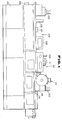
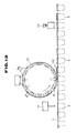
- Figure 1 shows a machine of the fill-and-pack in the non-germ atomosphere in which the present invention is comprised.
- the machine is composed of a container sterilization unit 104 and a fill-and-pack unit 110.
- the container sterilization unit 104 is composed of a sealed framework 113 (non-germ chamber) installed onto the supporting framework 115.
- the sealed framework 113 In the sealed framework 113, the container supplier 105, the sterilizer dispatching mouth 106, the ultraviolet rays apply means 107, the hot wind blow duct 108 and the hot wind sucking duct 109 are composed.
- At least a pair of rail 7 is installed in the sealed framework 113 and containers 5 are hung at their flanges 6 by the rail 7.
- the endless chain is installed to move intermittetly under the rail 7 and pushing plates are secured to the endless chain at a same interval. Each pushing plate pushes a container 5 hung on the rail 7 freely and send it forward.
- Each container 5 is first sterilized with such as hydrogen peroxide applied through the sterilizer apply mouth 12, and with ultraviolet rays applied from the ultraviolet rays applier 51, then it will be completely dried by hot wind.
- the container 5, after the sterilization is completed, is sent to the fill-and-pack unit 110.
- the fill-and-pack unit 110 comprises a shut framework 114 (sealed non-germ chamber) on the supporting framework 115.
- the shut framework 114 In the shut framework 114, the filling means 111, the lid sterilization means 101 and the press seal means 112 are installed.
- the temporal sealing means 102, the first positioning means (not shown in the drawings) that corrects the container's 5 position where a lid 8 is provided on, and the second positioning means (not shown in the drawings) that corrects the container's 5 position and support the container's flange 6 from underneath where it is pressed by the press seal means 112 for a complete sealing are also installed.
- the container 5 sent from the container sterilization unit 104 is carried intermittently in the fill-and-pack unit 110 with its flange 6 hung on the rail 7 until it arrives underneath of the filling means 111. There the food is filled up. Then the container 5 with the food filled up is agagin carried underneath of the lid sterilization means 101. After the container's position is adjusted by the first positioning means, a lid 8 is provided on the top of the container 5 from the lid sterilization means 101 and the lid 8 is partially sealed on the top of the container 5 by the temporal sealing means 102. Then the container 5 with the lid 8 on the top is sent to underneath of the press seal means 112. After the container's position is corrected by the second positioning means, the lid 8 is pressed by the press seal means 112 completing the seal of the container. The container 5 is, then, sent outside of the sealed framework 113.
- the lid sterilization means 101 is composed of the outer cylinder 1 which is secured by the bracket 18 to the frame wall 116 of the sealed framework 113, and the rotary drum 3 which is rotatably installed to the outer cylinder 1.
- the outer cylinder 1 as shown especially in Figures 4 and 5, comprises the wall cylinder 10 inside surface thereof is fixed smooth, and the side wall 17 that closes both side of the openings of the wall cylinder 10.
- the wall cylinder 10 has the carry-in mouth 11 for carrying the lid 8 in, the sterilizer apply mouth 12, the ultraviolet rays apply mouth 13, the hot wind passage mouth 14, and the carry-out mouth 15 for carrying out the sterilized lid 8.
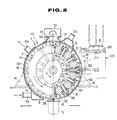
- the rotary drum 3 which rotates intermittently by regularized central degrees of an angle, is composed of the cylindrically shaped main drum 30, outer surface of which touches closely the inner surface of the cylindrically shaped wall cylinder 10, the rooms 31 created with the same regular intervals on the outer surface of the main drum 30, the side plates 32 that close the both opening sides of the main drum 30, the second sucking disk 42 which firmly fixed on the bottom of the room 31 (see Fig. 2), and the first sucking disk 38 (see also Fig. 2) which can move upwardly and downwardly through the bottom wall of the room 31.
- the shape of the carry-in mouth 11 is arranged same as that of the room 31.
- a lid 8 is provided to the right position from the lid supply means 103 into the room 31 through the carry-in mouth 11.
- the move arm 81 moves and the vacuum pat 82 holds the bottom lid 8 stocked in the lid magazine 80. It then moves into the room 31 and provide the lid 8 to the second sucking disk 42.
- a room 31 is located between the carry-in mouth 11 and the sterilizer apply mouth 12, therefore, the inside of the lid sterilization means 101 is successfully shut from the outside.
- the sterilizer apply mouth 12 and the ultraviolet rays apply mouth 13 are created close by to continuously complete sterilization and application of ultraviolet rays.
- Another room 31 is located between the ultraviolet rays mouth 13 and the hot wind passage mouth 14 to prevent the sterilizer from sneaking into the hot wind passage mouth 14.
- the hot wind passage mouth 14 is interconnected with four rooms 31. Hot wind blows through all these four rooms 31, thus the lids 8 can well be dried.
- the partial wall 16 is provided at about the middle of the hot wind passage mouth 14 to fully apply hot wind to the back side of the lid 18.
- the carry-out mouth 15 is made next to the hot wind passage mouth 14. There is no blocking element between them. Therefore, the first sucking disk 38 with the lid 8 can move upwardly (to the down direction at this position) and provides the lid 8 on the top of the container 5.
- At least one room 31 is located between the carry-out mouth 15 and the carry-in mouth 11 to block the passage between them.
- the sterilizer apply duct 50 is installed to the sterilizer apply mouth 12, and the ultraviolet rays applier 51 is installed with the shade cover 52 to the ultraviolet rays apply mouth 13.
- the hot wind passage mouth 14 is sealed by the cover plate 55.
- the hot wind supply duct 53 is installed at one side of the cover plate 55 and the hot wind exhaust duct 54 is installed at the other side of the cover plate 55. Hot wind, supplied from the hot wind supply duct 53, blows through each room 31 and is exhausted from the hot wind exhaust duct 54.
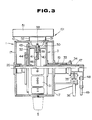
- the bearing boss 19 and the bearing 20 are installed to the frame wall 116 by the bracket 18. They organize the central element of parts such as the rotary drum 3, the cam plate 46 and the vacuum disk 44.
- the cam plate 46 and the vacuum disk 44 are fixed to the cam driving shaft 47 which is rotatably installed into the rotary shaft sleeve 33.
- the cam plate 46 enforces the first sucking disk 38 to move upwardly and downwardly.
- the vacuum disk 44 interconnects and disconnects the vacuum chamber (not shown) to both first sucking disk 38 and the second sucking disk 42.
- the cam plate 46 and the vacuum disk 44 rotate to one direction and the return direction together when the rotary arm 48 is driven by the up-down shaft 49.
- the first sucking disk 38 is installed on top of the pickup rod 39 airtightly and moveably upward and downward directions, which passes through the main drum 30.
- the spring 40 is installed to the pickup rod 39, one side of which touches to the cam wheel 41 and the other to the main drum 30.
- the cam wheel 41 is enforced to touch the cam plate's 46 surface by the elasticity of the spring 40.
- the vacuum manifold 43 placed airtightly touches the vacuum disk 44, is firmly secured to the side plate 32.
- the interconnection between the sucking disks 38,42 and the vacuum chamber (not shown in the drawings) is accomplished by the mutual rotation of the vacuum manifold 43 and the vacuum disk 44.
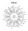
- the vacuum manifold 43 has the vacuum passages 45, facing toward the side plate 32, equivalent to the number of the rooms 31.
- Each vacuum passage 45 includes the V-shaped second passage 45b and the first passage 45a in the center of the second passage 45b. Both of the passages 45a,45b reaches to the other side of the vacuum manifold 43 through the first pass hole 45c and the second pass hole 45d.
- the vacuum disk 44 as shown in Figures 9 and 10, has the first bypass 44a and the first opening 44c, both connected to the first passage 45a, and the second bypass 44b and the second opening 44d, both connected to the second pass hole 45d.
- the vacuum disk 44 and the vacuum manifold 43 mutually rotates, interconnection and disconnection of the first passage 45a, the first bypass 44a and the first opening 44c can be accomplished.
- the vacuum disk 44 and the vacuum manifold 43 mutually rotates, interconnection and disconnection of the second passage 45b, the second bypass 44b and the second opening 44d can be completed. Therefore interconnection and disconnection between the both sucking disks 38,42 and the vacuum chamber can mechanically be achieved.
- Figure 11 shows the movement of the lid sterilization means 101.
- the first sucking disk moves back by elastic force of the spring 40 and as the cam wheel 41 follows the cam plate, and the lid 8 is sucked and held by the second sucking disk 42.
- the vacuum disk 44 rotates to one direction with the cam plate since both are mechanically connected to the cam driving shaft 47.
- the first passage 45a which is a passage for the first sucking disk 38 is disconnected from the first bypass 44a
- the second passage 45b is interconnected with the second bypass 44b which is a passage for the second sucking disk 42.
- the room 31 then revolves and comes by the sterilizer apply mouth 12 (position II), where the sterilizer is applied to the room 31 through the sterilizer apply duct 50 and the lid 8 is sterilized. While the room 31 is at position II, the lid 8 is first held by the second sucking disk 42 and then by the first sucking disk 38 as the cam plate 46 and the vacuum disk 44 rotate to the return direction together. Therefore, whole surface of the lid 8 can be exposed and sterilized.
- the room 31 then moves up by the ultraviolet rays apply mouth 13 (position III) where the lid 8 is also held alternatively by the first sucking disk 38 and by the second sucking disk. So whole surface of the lid 8 can be sterilized by the ultraviolet raids.
- the room 31 moves by the hot wind passage mouth 14, the drying zone (position IV), and there the lid 8 is completely dried.
- the lid 8 is first held by the second sucking disk 42 and then by the first sucking disk 38. Whole surface of the lid 8 can be exposed and dried well.
- the first sucking disk 38 moves upwardly to the downward direction and provide the lid 8 on top of the container 5.
- Providing the lid 8 by the first sucking disk 38 at its center and not by the second sucking disk 42 at its edge is advantageous when the lid 8 is temporarily sealed at the next procedure.
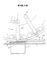
- the temporal sealing means 102 is installed underneath of the lid sterilization means 101.
- the moving rod 60 placed on the rail 7 and having the heater 61 at the end, is rotatably installed to the installation frame 79 with the moving shaft 63 and the shaft receiver 62 at the end.
- the moving arm 64 is firmly installed to the base end of the moving rod 60.
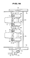
- Figure 14 to 16 show the temporal sealing means 102 which is driven with a cam structure.
- the coil spring 67 is placed between the moving arm 64 and the installation frame 79, and the cam follower 66 is rotatably provided at the end of the moving arm 64.
- the cam roller 68 whose center is rotatably installed to the rotary axis 69 that attaches to the fixed frame 78 with the bearing 70, is placed upper part of the cam follower 66.
- the cam roller 68 includes the bigger-diameter cam surface and the smaller-diameter cam surface.
- the other end of the ratary axis is mechanically connected to the driving rod 72 through the follow gear 71 and the driving gear 73.
- the driving rod 72 is arranged to continuosly rotate and its rotation is synchronized with the intermittent movenment of the container 5 on the rail 7.
- the cam follower 66 runs on the cam roller's 68 smaller-diameter surface that enables the coil spring 67 to push the moving arm 64 upwardly.
- the top end of the moving arm 64 downwardly moves and the heater 61 pushes the lid 8 onto the flange 6 of the container 5 and seals the lid 8 partially and temporarily.
- the cam follower 66 again runs on the biger-diameter surface of the cam roller 68.
- the moving arm 64 then is pushed downwardly and the heater 61 moves upwardly.
- cam's movement is mechanically synchronized with the movement of the container 5, therefore setting the timing of the sealing is easier and the sealing procedure can well be achieved.
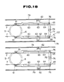
- FIG. 17 to 19 shows the temporal sealing means 102 driven by a cylinder 74.
- the cylinder 74 is firmly fixed to the fixed frame 78 interconnected by the install frame 77, and the end of the cylinder rod is connected to the connecting plate 75 on the end of the moving arm 64.
- the cylinder 74 receives a signal and the cylinder rod moves upwardly and pulls up the moving arm 64.
- the top end of the moving rod 60 moves downwardly and the heater 61 pushes the lid 8 onto the flange 6 of the container 5 and temporarily seal it.
- the temporal sealing is done only after the container 5 reaches on the right place and a lid 8 is correctly provided on the container 5, therefore, if either one or both of the process has not been successfully done, the sealing procedure will not proceed.
- the advantages of this structure is that the heater 61 will not directly touches the rail 7 and prevent damgages of the rail 7 by heat, and that a test run of the temporal sealing means 102 can rather easily be done because the cylinder's 74 movement is not synchronized with the container's.
- the width of the cam roller 68 is arranged much wider than the cam follower 66, and for the cylinder structure, the moving arm 64 and the connecting plate 75 are mechanically connected by inserting the pin 65 into the elongated hole 76.
- each room 31 in the lid sterilization means 101 is air tightly segregated from other rooms 31 and from the outside, the out side air, which contains germs, does not enter into the room 31 nor the sterilizer does not leak.
- a lid 8 is held by the sucking disk 38,42 in the room 31, thus any size of the lid 8 can be held by the same sucking disk 38,42. It is advantageous because the sucking disk does not have to be replaced by another one when different size of the lid 8 is to be sealed, and therefore the non-germ atomosphere can be kept still same. As a result, a lot of time and work can be saved.
- a lid 8 is held by the first sucking disk 38 and the second sucking disk 42 at different parts.
- whole surface of the lid 8 is exposed and the whole surface can well be sterilized.
- the intermittent movement can rather easily be achieved compared, for example, to non-drum element. Therefore, it is possible to make the means simpler and more compact.
- the first sucking disk 38 works during the sterilization process and drying process as a lid holder. It also works as a lid provider. Since the first sucking disk 38 is applicable to the both, it is not necessary to install another means as a lid provider. This also makes the apparatus become simpler and more compact.
- sucking procedure of the sucking disks 38,42 can well be accomplished.
- the heater 61 of the temporal sealing means 102 is located right above the container 5 in the sealing position, thus temporal sealing can well be done by only forcing the heater 61 downwardly onto the lid 8.
- the heater 61 is installed adjustably to the width direction, so even when the rail's distance is widened or narrowed for a different size of the container 5, the heater's 61 position can be adjusted easily.
Landscapes
- Engineering & Computer Science (AREA)
- Mechanical Engineering (AREA)
- Food Preservation Except Freezing, Refrigeration, And Drying (AREA)
- Closing Of Containers (AREA)
Priority Applications (1)
| Application Number | Priority Date | Filing Date | Title |
|---|---|---|---|
| EP92113629A EP0523745B1 (de) | 1988-03-25 | 1989-03-16 | Verfahren und Vorrichtung zum provisorischen Verschweissen eines Deckels |
Applications Claiming Priority (4)
| Application Number | Priority Date | Filing Date | Title |
|---|---|---|---|
| JP71310/88 | 1988-03-25 | ||
| JP63071310A JPH01254522A (ja) | 1988-03-25 | 1988-03-25 | シート状蓋体の滅菌処理方法と装置 |
| JP147314/88 | 1988-06-15 | ||
| JP63147314A JP2548305B2 (ja) | 1988-06-15 | 1988-06-15 | 仮シール方法と仮シール装置 |
Related Child Applications (1)
| Application Number | Title | Priority Date | Filing Date |
|---|---|---|---|
| EP92113629.7 Division-Into | 1992-08-10 |
Publications (3)
| Publication Number | Publication Date |
|---|---|
| EP0334216A2 true EP0334216A2 (de) | 1989-09-27 |
| EP0334216A3 EP0334216A3 (en) | 1990-07-04 |
| EP0334216B1 EP0334216B1 (de) | 1993-07-14 |
Family
ID=26412425
Family Applications (2)
| Application Number | Title | Priority Date | Filing Date |
|---|---|---|---|
| EP89104748A Expired - Lifetime EP0334216B1 (de) | 1988-03-25 | 1989-03-16 | Verfahren und Vorrichtung zum Sterilisieren von Deckeln |
| EP92113629A Expired - Lifetime EP0523745B1 (de) | 1988-03-25 | 1989-03-16 | Verfahren und Vorrichtung zum provisorischen Verschweissen eines Deckels |
Family Applications After (1)
| Application Number | Title | Priority Date | Filing Date |
|---|---|---|---|
| EP92113629A Expired - Lifetime EP0523745B1 (de) | 1988-03-25 | 1989-03-16 | Verfahren und Vorrichtung zum provisorischen Verschweissen eines Deckels |
Country Status (4)
| Country | Link |
|---|---|
| US (2) | US4981649A (de) |
| EP (2) | EP0334216B1 (de) |
| CA (1) | CA1321462C (de) |
| DE (2) | DE68907508T2 (de) |
Cited By (5)
| Publication number | Priority date | Publication date | Assignee | Title |
|---|---|---|---|---|
| US4987721A (en) * | 1989-01-10 | 1991-01-29 | Gasti Verpackungsmaschinen Gmbh | Method of and apparatus for the sterilization of stacked packaging elements |
| DE102008022708A1 (de) * | 2008-05-07 | 2009-11-12 | Khs Ag | Verfahren sowie Verschlussvorrichtung zum Verschließen von Dosen oder dergleichen Behältern sowie Packmittel |
| DE10234886B4 (de) * | 2002-07-31 | 2016-12-29 | Gasti Verpackungsmaschinen Gmbh | Verpackungsmaschine |
| CN111110897A (zh) * | 2018-11-01 | 2020-05-08 | 宁波方太厨具有限公司 | 一种消毒柜 |
| CN113958159A (zh) * | 2021-08-03 | 2022-01-21 | 温州市人民医院 | 一种便于医护人员换衣的简易缓冲房 |
Families Citing this family (22)
| Publication number | Priority date | Publication date | Assignee | Title |
|---|---|---|---|---|
| US5606169A (en) * | 1995-09-25 | 1997-02-25 | Westvaco Corporation | Ultraviolet light sterilization retrofit for paperboard packaging filling machines |
| US5857309A (en) * | 1997-03-28 | 1999-01-12 | Tetra Laval Holdings & Finance, S.A. | Apparatus for sterilizing a spout assembly of a container |
| FI104245B1 (fi) * | 1998-10-12 | 1999-12-15 | Upm Kymmene Corp | Laite elintarvikepakkausten kansien steriloimiseksi |
| DE19851654A1 (de) * | 1998-11-10 | 2000-05-11 | Tetra Laval Holdings & Finance | Verfahren zum Sterilisieren von Schraubkappen und Vorrichtung zum Sterilisieren |
| DE29908075U1 (de) * | 1999-05-06 | 2000-09-14 | GEA Finnah GmbH, 48683 Ahaus | Vorrichtung zum Verschließen von Kunststoffflaschen |
| FR2827835B1 (fr) * | 2001-07-26 | 2003-12-19 | Erca Formseal | Dispositif pour decouper une rangee d'opercules dans une bande a opercules et les fixer sur une rangee de recipients remplis |
| DE102004033219A1 (de) * | 2004-07-09 | 2006-02-02 | Roche Diagnostics Gmbh | Verfahren zur selektiven Sterilisation von diagnostischen Testelementen |
| PT2323700E (pt) * | 2008-08-26 | 2012-01-20 | Sidel Spa | Aparelho e método de esterilização de elementos de fecho de recipientes |
| FR2942618A1 (fr) * | 2009-03-02 | 2010-09-03 | Sodetech | Procede et installation pour le conditionnement sous vide en continu de produits alimentaires |
| ITTV20090152A1 (it) * | 2009-07-28 | 2011-01-29 | Galdino Candiotto | Macchina automatica per la disinfezione, riempimento e sigillatura di coppette o contenitori preformati. |
| DE102010052207B4 (de) * | 2010-11-24 | 2017-08-31 | Khs Gmbh | Vorrichtung zum Sterilisieren von Verschlüssen für Behälter |
| DE102013217665A1 (de) * | 2013-09-04 | 2015-03-05 | Krones Ag | Vorrichtung zum Bedrucken von Behältern |
| CN104692117A (zh) * | 2015-01-13 | 2015-06-10 | 无锡万洪电子机械有限公司 | 一种多工位间隙转动真空吸持机构 |
| ITUB20155739A1 (it) * | 2015-11-19 | 2017-05-19 | Weightpack Srl | Impianto di sigillatura di contenitori |
| ITUB20155723A1 (it) * | 2015-11-19 | 2017-05-19 | Weightpack Srl | Impianto di sigillatura di contenitori |
| US11738979B2 (en) | 2016-03-16 | 2023-08-29 | Khs Gmbh | Arrangement for disinfecting can lids for closing cans |
| DE102016104859A1 (de) * | 2016-03-16 | 2017-09-21 | Claranor Sa | Anordnung zum Desinfizieren von Dosendeckeln zum Verschließen von Dosen |
| JP7002326B2 (ja) * | 2017-12-26 | 2022-01-20 | 川崎重工業株式会社 | 蓋閉じ装置及び蓋閉じ方法 |
| DE102018220486A1 (de) * | 2018-11-28 | 2020-05-28 | Robert Bosch Gmbh | Verfahren und Vorrichtung zum Sterilisieren von Verschlusselementen für Verpackungsbehälter und deren Verwendung |
| CN109650059B (zh) * | 2019-01-25 | 2021-06-11 | 东莞市威耐科智能装备有限公司 | 基于凸轮驱动升降的多头取料装置 |
| FR3092570A1 (fr) * | 2019-02-12 | 2020-08-14 | Capkawa | Capsule munie d'un opercule partiellement assemble |
| BR102023013369A2 (pt) * | 2022-07-19 | 2024-01-30 | Ferrum Packaging Ag | Suprimento de tampas para uma máquina fechadora e uma máquina fechadora |
Family Cites Families (25)
| Publication number | Priority date | Publication date | Assignee | Title |
|---|---|---|---|---|
| US1938821A (en) * | 1929-02-09 | 1933-12-12 | Margaret F Fenn | Method and means for vacuumizing, sterilizing, and sealing containers |
| US2885845A (en) * | 1956-03-21 | 1959-05-12 | W F And John Barnes Company | Method and apparatus for aseptically canning |
| US3018184A (en) * | 1958-12-23 | 1962-01-23 | Martin William Mck | Aseptic canning process and apparatus |
| US3050914A (en) * | 1959-05-25 | 1962-08-28 | Reddi Wip Inc | Sterilizing procedures for aseptic canning |
| US3323856A (en) * | 1965-04-19 | 1967-06-06 | Dole Eng Co James | Sterilizer for container covers |
| US3481109A (en) * | 1966-12-08 | 1969-12-02 | Nat Res Dev | Container sterilising and filling apparatus |
| CH497027A (de) * | 1968-09-20 | 1970-09-30 | Sulzer Ag | Bestrahlungsanlage mit Drehschieber zum Ein- und Ausschleusen von Ladungen eines zu bestrahlenden Gutes |
| DE1955974A1 (de) * | 1969-11-07 | 1972-11-30 | Ganzhorn & Stirn Spezialfabrik | Becherabstapel-Vorrichtung |
| NL7002902A (de) * | 1970-03-02 | 1971-09-06 | Unilever Nv | |
| US3714758A (en) * | 1971-03-26 | 1973-02-06 | Reynolds Metals Co | Method and apparatus for forming a depression in a cover member of a container construction |
| US3687261A (en) * | 1971-04-02 | 1972-08-29 | Dole James Corp | Conveying system |
| US3834523A (en) * | 1972-02-24 | 1974-09-10 | Rexnord Inc | Conveyor guided by dynamic vibration absorbers |
| CH556269A (de) * | 1972-04-17 | 1974-11-29 | Hamba Maschf | Vorrichtung zur sterilen abfuellung von nahrungs- und genussmitteln. |
| US3890767A (en) * | 1973-11-23 | 1975-06-24 | Richard S Cawrse | Apparatus for applying lids to containers |
| US3971188A (en) * | 1973-11-23 | 1976-07-27 | Cawrse Richard S | Apparatus and method for applying lids to containers |
| US3908340A (en) * | 1974-03-25 | 1975-09-30 | Anderson Bros Mfg Co | Apparatus for feeding and applying individual lids to containers |
| US4391080A (en) * | 1979-09-20 | 1983-07-05 | The Mead Corporation | Method for providing an inert sterile atmosphere in an aseptic packaging machine |
| GB2071565B (en) * | 1980-03-14 | 1984-02-15 | Ti Fords Ltd | Methods and machines for applying and sealing diaphragm closures to the mouths of containers |
| FR2528386B1 (fr) * | 1982-06-14 | 1986-04-11 | Erca Holding | Procede et installation de conditionnement d'un produit |
| JPS59115221A (ja) * | 1982-12-20 | 1984-07-03 | 四国化工機株式会社 | 包装機械におけるキヤツプ殺菌方法 |
| US4590734A (en) * | 1984-06-04 | 1986-05-27 | Shikoku Kakooki Co., Ltd. | Packaging machine |
| US4566251A (en) * | 1985-01-07 | 1986-01-28 | Ex-Cell-O Corporation | Carton forming, sterilizing, filling and sealing machine |
| US4575987A (en) * | 1985-04-25 | 1986-03-18 | Vercon, Inc. | Apparatus for closing a container |
| FR2594410B1 (fr) * | 1986-02-19 | 1988-12-09 | Lyonnaise Bouchage | Procede de prepositionnement d'opercules sur le goulot des recipients sur lesquels ils doivent etre thermoscelles et dispositif pour sa mise en oeuvre |
| DE3716096A1 (de) * | 1987-05-14 | 1988-12-01 | Hamba Maschf | Becherfuellwerk fuer nahrungs- und genussmittel, insbesondere fuer molkereiprodukte |
-
1989
- 1989-03-10 US US07/321,870 patent/US4981649A/en not_active Expired - Lifetime
- 1989-03-16 DE DE89104748T patent/DE68907508T2/de not_active Expired - Fee Related
- 1989-03-16 EP EP89104748A patent/EP0334216B1/de not_active Expired - Lifetime
- 1989-03-16 DE DE68923713T patent/DE68923713T2/de not_active Expired - Fee Related
- 1989-03-16 CA CA000593965A patent/CA1321462C/en not_active Expired - Fee Related
- 1989-03-16 EP EP92113629A patent/EP0523745B1/de not_active Expired - Lifetime
-
1990
- 1990-07-16 US US07/552,994 patent/US5076039A/en not_active Expired - Fee Related
Cited By (5)
| Publication number | Priority date | Publication date | Assignee | Title |
|---|---|---|---|---|
| US4987721A (en) * | 1989-01-10 | 1991-01-29 | Gasti Verpackungsmaschinen Gmbh | Method of and apparatus for the sterilization of stacked packaging elements |
| DE10234886B4 (de) * | 2002-07-31 | 2016-12-29 | Gasti Verpackungsmaschinen Gmbh | Verpackungsmaschine |
| DE102008022708A1 (de) * | 2008-05-07 | 2009-11-12 | Khs Ag | Verfahren sowie Verschlussvorrichtung zum Verschließen von Dosen oder dergleichen Behältern sowie Packmittel |
| CN111110897A (zh) * | 2018-11-01 | 2020-05-08 | 宁波方太厨具有限公司 | 一种消毒柜 |
| CN113958159A (zh) * | 2021-08-03 | 2022-01-21 | 温州市人民医院 | 一种便于医护人员换衣的简易缓冲房 |
Also Published As
| Publication number | Publication date |
|---|---|
| US5076039A (en) | 1991-12-31 |
| US4981649A (en) | 1991-01-01 |
| DE68923713D1 (de) | 1995-09-07 |
| EP0334216A3 (en) | 1990-07-04 |
| DE68907508T2 (de) | 1994-02-17 |
| EP0523745A1 (de) | 1993-01-20 |
| EP0523745B1 (de) | 1995-08-02 |
| DE68923713T2 (de) | 1996-01-18 |
| DE68907508D1 (de) | 1993-08-19 |
| CA1321462C (en) | 1993-08-24 |
| EP0334216B1 (de) | 1993-07-14 |
Similar Documents
| Publication | Publication Date | Title |
|---|---|---|
| EP0334216A2 (de) | Verfahren und Vorrichtung zum Sterilisieren von Deckeln | |
| US5157895A (en) | Positioning and press-sealing means | |
| EP0342690B1 (de) | Maschine zum Füllen und Verschliessen in einer keimfreien Atmosphäre | |
| US7328556B2 (en) | Bag sealing system and method | |
| FI68577B (fi) | Foerfarande och anordning foer aostadkommande av en vakuumtillsluten foerpackning | |
| US5687542A (en) | Isolation module for molding and packaging articles substantially free from contaminants | |
| DK1021338T3 (da) | Apparat til konditionering af produkter under en kontrolleret atmosfære i emballager, som er forsynet med låg af en film | |
| JP2002544069A (ja) | プラスッチック瓶を閉鎖するための装置 | |
| US3018184A (en) | Aseptic canning process and apparatus | |
| US6024917A (en) | Sterilization device and method for sterilizing objects | |
| JPH10181713A (ja) | 間歇回転形充填包装機における包装袋の真空方法とその真空装置 | |
| JPH0234163Y2 (de) | ||
| JP3596042B2 (ja) | ガス置換装置を備えたキャッパ | |
| CN110641747A (zh) | 一种预制盖旋转盒式气调包装机 | |
| DE59904055D1 (de) | Verfahren und vorrichtung zum öffnen und füllen vorgefertigter beutelverpackungen | |
| WO2005058704A1 (en) | A machine for filling packages, in particular sacks and/or bags | |
| CA1334108C (en) | Positioning and press-sealing means | |
| CN107813117A (zh) | 一种盖体的组装设备及其组装方法 | |
| JPS63294320A (ja) | 上部が開いた容器に液体を無菌充填する方法および装置 | |
| JPH0558993B2 (de) | ||
| CN106829035A (zh) | 一种洁净环境下的包装设备及包装工艺 | |
| JPH01279004A (ja) | 押圧装置 | |
| WO2004011335A1 (en) | Method and machine for filling pouch packages or envelopes, in particular for food and/or pharmaceutical products | |
| KR20010035716A (ko) | 밀폐용기의 통풍밸브 자동부착장치 | |
| JPS6470326A (en) | Vacuum packing apparatus having vacuum cooling means |
Legal Events
| Date | Code | Title | Description |
|---|---|---|---|
| PUAI | Public reference made under article 153(3) epc to a published international application that has entered the european phase |
Free format text: ORIGINAL CODE: 0009012 |
|
| AK | Designated contracting states |
Kind code of ref document: A2 Designated state(s): DE FR GB |
|
| PUAL | Search report despatched |
Free format text: ORIGINAL CODE: 0009013 |
|
| AK | Designated contracting states |
Kind code of ref document: A3 Designated state(s): DE FR GB |
|
| 17P | Request for examination filed |
Effective date: 19900725 |
|
| 17Q | First examination report despatched |
Effective date: 19920331 |
|
| GRAA | (expected) grant |
Free format text: ORIGINAL CODE: 0009210 |
|
| AK | Designated contracting states |
Kind code of ref document: B1 Designated state(s): DE FR GB |
|
| XX | Miscellaneous (additional remarks) |
Free format text: TEILANMELDUNG 92113629.7 EINGEREICHT AM 16/03/89. |
|
| REF | Corresponds to: |
Ref document number: 68907508 Country of ref document: DE Date of ref document: 19930819 |
|
| ET | Fr: translation filed | ||
| PLBE | No opposition filed within time limit |
Free format text: ORIGINAL CODE: 0009261 |
|
| STAA | Information on the status of an ep patent application or granted ep patent |
Free format text: STATUS: NO OPPOSITION FILED WITHIN TIME LIMIT |
|
| 26N | No opposition filed | ||
| REG | Reference to a national code |
Ref country code: GB Ref legal event code: IF02 |
|
| PGFP | Annual fee paid to national office [announced via postgrant information from national office to epo] |
Ref country code: GB Payment date: 20020227 Year of fee payment: 14 |
|
| PG25 | Lapsed in a contracting state [announced via postgrant information from national office to epo] |
Ref country code: GB Free format text: LAPSE BECAUSE OF NON-PAYMENT OF DUE FEES Effective date: 20030316 |
|
| GBPC | Gb: european patent ceased through non-payment of renewal fee |
Effective date: 20030316 |
|
| PGFP | Annual fee paid to national office [announced via postgrant information from national office to epo] |
Ref country code: DE Payment date: 20070329 Year of fee payment: 19 |
|
| PGFP | Annual fee paid to national office [announced via postgrant information from national office to epo] |
Ref country code: FR Payment date: 20070323 Year of fee payment: 19 |
|
| REG | Reference to a national code |
Ref country code: FR Ref legal event code: ST Effective date: 20081125 |
|
| PG25 | Lapsed in a contracting state [announced via postgrant information from national office to epo] |
Ref country code: DE Free format text: LAPSE BECAUSE OF NON-PAYMENT OF DUE FEES Effective date: 20081001 |
|
| PG25 | Lapsed in a contracting state [announced via postgrant information from national office to epo] |
Ref country code: FR Free format text: LAPSE BECAUSE OF NON-PAYMENT OF DUE FEES Effective date: 20080331 |