EP0334254A2 - Liaison de données optique pour mise en service magnétique - Google Patents
Liaison de données optique pour mise en service magnétique Download PDFInfo
- Publication number
- EP0334254A2 EP0334254A2 EP89104928A EP89104928A EP0334254A2 EP 0334254 A2 EP0334254 A2 EP 0334254A2 EP 89104928 A EP89104928 A EP 89104928A EP 89104928 A EP89104928 A EP 89104928A EP 0334254 A2 EP0334254 A2 EP 0334254A2
- Authority
- EP
- European Patent Office
- Prior art keywords
- light
- connector
- optical
- data link
- optical communication
- Prior art date
- Legal status (The legal status is an assumption and is not a legal conclusion. Google has not performed a legal analysis and makes no representation as to the accuracy of the status listed.)
- Granted
Links
Images

Classifications
-
- H—ELECTRICITY
- H04—ELECTRIC COMMUNICATION TECHNIQUE
- H04B—TRANSMISSION
- H04B10/00—Transmission systems employing electromagnetic waves other than radio-waves, e.g. infrared, visible or ultraviolet light, or employing corpuscular radiation, e.g. quantum communication
- H04B10/80—Optical aspects relating to the use of optical transmission for specific applications, not provided for in groups H04B10/03 - H04B10/70, e.g. optical power feeding or optical transmission through water
- H04B10/801—Optical aspects relating to the use of optical transmission for specific applications, not provided for in groups H04B10/03 - H04B10/70, e.g. optical power feeding or optical transmission through water using optical interconnects, e.g. light coupled isolators, circuit board interconnections
-
- G—PHYSICS
- G02—OPTICS
- G02B—OPTICAL ELEMENTS, SYSTEMS OR APPARATUS
- G02B6/00—Light guides; Structural details of arrangements comprising light guides and other optical elements, e.g. couplings
- G02B6/24—Coupling light guides
- G02B6/42—Coupling light guides with opto-electronic elements
- G02B6/4295—Coupling light guides with opto-electronic elements coupling with semiconductor devices activated by light through the light guide, e.g. thyristors, phototransistors
Definitions
- This invention relates to an optical data link, and more particularly, to a connector for an optical data link that electrically activates an electronic device when the connector is plugged into the electronic device.
- batteries typically have a finite life after which they must be either replaced or recharged. Consequently, it is generally desirable to disconnect the batteries from the device that is being powered when the device is not being used. For example, if the function of the electrical device is to output data to a second device, a switch may be turned off to electrically deactivate the device when the electrical device is not connected to the second device.
- Electrical devices are typically connected to each other through electrical cables that mate with the electrical devices through electrical connectors.
- These connectors typically include a multi-pin plug that is inserted into a correspondingly configured socket.
- the battery can be automatically disconnected from the device when the plug is removed from the socket. This function can be accomplished by connecting the battery for the electrical device in series with two pins of a socket mounted on the device, and then interconnecting two corresponding pins of the plug.
- a circuit is completed through the plug and socket, thereby connecting the battery to the components of the electrical device.
- the electrical device is automatically activated when the plug is inserted in the socket.
- EMPs electromagnetic pulses
- EMI electromagnetic interference
- One alternative data link that can be used is an optical data link having a light emitter in a first connector member optically coupled to a light detector in a second connector member.
- the optical data link can also be made bidirectional by mounting a second light emitter in the second connector member and a second light detector in the first connector member.
- optical link can be used in many applications, it is generally not suitable for use in an application where an electrical, battery powered device is to be activated automatically when a connector is plugged into the device.
- An optical link cannot be used in this application because the optical connector does not have any electrical pins that can be interconnected to connect the battery to the device when the connector is plugged into the electrical device. Consequently, it has not been considered possible to use an optical data link for automatically activating an electrical device when the data link connector is plugged into the device.
- an optical data link for transferring data from a first connector to a second connector.
- a first optical communication component is mounted in one of the connectors, and it emits light as a function of a binary data signal.
- a second optical communication component such as a phototransistor, is mounted in the other connector, and it detects light emitted by the first optical component when the first and second connectors engage each other.
- the data link also actuates an electrical device connected to the second connector when the first and second connectors engage each other.
- a magnet is mounted in the first connector, and a magnetically sensitive switch is mounted in the second connector so that the magnetic field from the magnet closes the switch when the first and second connectors engage each other.
- the switch is connected to the electrical device to activate the electrical device when the switch is closed.
- the data link may include a second light-emitting component and a second light-detecting component to provide bidirectional data transfer to and from said electrical device.
- the light-detecting component is preferably a phototransistor, and it is preferably connected to an interface circuit that maintains a substantially constant voltage across the phototransistor to allow it to func tion as a current switch.
- the light-emitting component is preferably a light-emitting diode, and it is preferively driven by an interface circuit that limits the current flow through the light-emitting diode when the binary data signal is applied to the light-emitting diode.
- FIG. 1 One application for the magnetically activating optical data link is illustrated in Figure 1.
- a conventional ambulatory blood pressure recorder 10 is connected to a conventional blood pressure cuff 12 through a pneumatic tube 14.
- the monitor 10 is typically worn by the patient throughout the day so that the patient's blood pressure can be periodically measured and recorded in the recorder 10.
- the data stored in the recorder 10 is read out at the termination of the test into a conventional readout device 16 which produces a visual hard-copy record of the patient's blood pressure for examination by a physician.
- One method of allowing data to be transferred from the blood pressure recorder 10 to the readout device, while still electrically isolating the recorder 10 from the readout device 16, is to connect the recorder 10 to the readout device 16 through an optical data link.
- the optical data link includes an optical fiber cable 20 extending between a pair of optical connectors 22, 24.
- the optical connector 22 plugs into a suitable receptacle (not shown) in the readout device 16, while the optical connector 24 plugs into a suitable receptacle (not shown) in the blood pressure recorder 10.
- the recorder 10 includes a light emitter (not shown) adjacent its receptacle that is modulated in a binary manner.
- the light from the emitter is coupled through the optical fiber cable 20 to a light detector (not shown) mounted in the readout device 16 adjacent its connector.
- the readout device 16 can include a light emitter and the recorder 10 can include a light detector to allow data or control signals to be transmitted from the readout device 16 to the recorder 10.
- an electrical cable 20′ can be electrically connected to the readout device 16 through an electrical connector 22′.
- the optical connector 24 that plugs into the recorder 10 then contains the light detector that would otherwise be mounted in the readout device if an optical fiber cable were used.
- the optical connector 24 would also contain a light emitter for bidirectional data transfer. Light is coupled from the light emitter in the recorder 10 (and to the light detector in a bidirectional system) in the same manner as if an optical fiber is used except that the coupling is direct rather than through an optical fiber cable.
- optical data links are their inability to automatically energize the blood pressure recorder 10 when it is connected to the readout device 16.
- the optical connector 24 does not include any electrical pins that make contact with an electrical socket in the recorder 10. As a result, it is not possible to place the battery powering the recorder 10 in series with these contacts. An optical data link would thus seem unusable where the recorder 10 is to be automatically energized when the connector 24 is plugged into the recorder 10.
- an electrical device can be automatically energized when the optical connector of an optical data link is plugged into the device using a magnet embedded in the connector 24 and a magnetically sensitive reed switch mounted in the recorder 10.
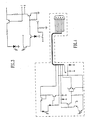
- One embodiment of an optical data link that can automatically energize an electrical device, such as the recorder 10, is illustrated in Figure 2.
- the blood pressure recorder 10 includes an optical connector 28 that is adapted to mate with the connector 24′ ( Figure 1) on the cable 20′.
- a conventional light emitter 30, such as a light-emitting diode, and a conventional light detector 32, such as a photosensitive transistor, are mounted on a circuit board 34 in the recorder 10 adjacent the connector 28.
- the light emitter 30 and the light detector 32 each include a pair of leads 36, 38, respectively, that are connected to an interface circuit 40 described in detail below.
- a conventional, magnetically sensitive reed switch 42 is also mounted on the circuit board 34 adjacent the connector 28 and is connected to the interface circuit 40 through a pair of leads 44.
- a battery 50 is connected to a positive power supply terminal 52 through the reed switch 42 and leads 44 to supply power to the recorder 10 when the reed switch is closed.
- the recorder 10 contains a conventional circuitry that need not be explained in detail here. Other electrical devices will, of course, utilize other circuitry, but they will also be powered by a DC voltage supplied by a battery 50. Circuits requiring multiple or differing polarity voltages can be powered by multiple batteries through multiple reed switches.
- the connector 24′ mounted on the cable 20′ includes a housing 60 adapted to fit into the connector 28 in the recorder 10.
- the housing 60 encloses a bar magnet 62 and a circuit board 64 on which are mounted a number of electrical components of a cable interface circuit 65 described below, including a conventional light emitter 66 and a conventional light detector 68.
- the light emitter 66 in the connector 24′ is mounted opposite the light detector 32 in the connector 28 while the light detector 68 in the connector 24′ is mounted opposite the light emitter 30 in the connector 28.
- a transparent window 70 is formed in the housing 60 adjacent the light emitter 66 and light detector 68. The transparent window 70 allows the light emitter 30 to communicate with the light detector 68 and the light emitter 66 to communicate with the light detector 32.
- Conductors in the cable 20′ terminate at the circuit board 64.
- a strain relief member 72 is formed at the end of the cable 20′ to resist axial forces exerted on the cable 20′.
- the interface circuit 40 in the recorder 10, as illustrated in Figure 3, receives a binary transmit signal "T” and outputs a binary receive signal "R". These signals have one of two values which, in accordance with conventional RS-232 practice, are positive and negative voltages having an absolute value of at least 5 volts.
- the transmit signal T is applied to the base of a transistor switch 80 to turn transistor 80 on and allow current to flow through the light emitter 30 (i.e., a light-emitting diode) and a current-limiting resistor 82 when the transmit signal T is negative.
- the transmit signal is positive, the base-emitter junction of transistor 80 is reverse biased to cut off transistor 80 and terminate the flow of current through the light emitter 30.
- the light detector 32 is a conventional photo transistor switch that becomes conductive when it is illuminated.
- the transistor does not have a base connection.
- this capacitance can cause a relatively slow switching speed if the collector-to-emitter voltage varies appreciably. It is therefore important to maintain the voltage across the phototransistor 32 relatively constant so that the phototransistor functions as a current switch.
- the phototransistor becomes conductive, the voltage on the emitter of phototransistor 32 is maintained at about 1.4 volts by the current flow through the base/emittor junction of transistor 84 and diode 86.
- the phototransistor 32 When the phototransistor 32 is cut off, its emitter is floating, since the phototransistor 32 does not supply any current to the emitter of transistor 84 to turn transistor 84 on. Thus, the voltage across phototransistor 32 remains relatively constant to minimize the effect of the Miller capacitance.
- the phototransistor is cut off when it is not exposed to light, thereby cutting off transistor 84.
- the base of transistor 90 is then biased to ground through resistor 92 to hold transistor 90 at cutoff.
- the receive signal R receives the supply voltage through resistor 94.
- the phototransistor 32 does not detect light, the receive signal R is high.
- the photodetector 32 when the photodetector 32 detects light, it supplies current to the transistor 84 to turn on transistor 84. The transistor 84 then turns on transistor 90 to pull the receive signal down to zero volts. Thus, when the phototransistor 32 detects light, the receive signal R is low.
- the interface circuit 65 in the connector 24′ is somewhat similar in structure and operation to the interface circuit 40 in the recorder 10.
- the interface circuit 65 as illustrated in Figure 4, likewise receives a transmit signal TXD and generates a receive signal RXD.
- the interface circuit 65 also receives a negative power supply signal in addition to the positive power supply signal received by the interface circuit 40.
- the interface circuit 40 outputs a receive signal R that varies between 0 and a positive voltage
- the interface circuit 65 outputs a receive signal RXD that varies between positive and negative voltages.
- the transmit signal TXD is applied to the emitter of transistor 100 and to the base of transistor 100 through resistor 102.
- the TXD signal is negative, the base-emitter junction of transistor 100 is reverse biased so that no current flows through light emitter 66 (i.e., light-emitting diode).
- the TXD signal is positive, the base-emitter junction of transistor 100 becomes forward biased through resistor 102, thereby turning on transistor 100 and allowing current to flow through the light emitter 66.
- Current flowing through light emitter 66 then flows through diode 104 and resistor 106 so that the voltage across resistor 104 is proportional to the current through the light emitter 66.
- the base-emitter junction of transistor 108 becomes forward biased, thereby turning on transistor 108 and causing it to draw current through resistor 110 and resistor 102.
- the voltage that transistor 100 applies to light emitter 66 decreases.
- the resistors 106, 110 and transistor 108 thus function as a current-limiting circuit to limit the current through the light emitter 66 to a predetermined value.
- the receiver portion of the interface circuit 65 maintains a substantially constant voltage across a phototransistor serving as the light detector 68.
- the base of transistor 120 is grounded so that transistor 120 continuously applies about -0.7 volt to the collector of the phototransistor 68.
- the emitter of the phototransistor 68 is connected to the negative power supply voltage so that the voltage across the phototransistor is constant.
- the collector of transistor 122 is held at the negative power supply voltage through resistor 128.
- the collector of transistor 122 is connected to a pair of transistors 130, 132 arranged as bipolar emitter followers. The transistors 130, 132 thus output the negative power supply voltage when the phototransistor does not detect light.
- the phototransistor 68 When light is applied to the phototransistor 68, the phototransistor becomes conductive, thereby drawing current through resistor 124 and resistor 134. As the voltage across resistor 124 drops, transistor 122 turns on, thereby pulling the bases of emitter follower transistors 130, 132 to the positive supply voltage. Transistor 130 then outputs the positive supply voltage as the RXD signal when the phototransistor 68 is detecting light.
- battery 50 is disconnected from the circuitry in the blood pressure recorder 10, including the interface circuit 40, when the connector 24′ is not inserted in the connector 28.
- the life of the battery 50 is preserved between replacement or recharging.
- the magnetic field generated by the magnet 62 closes the reed switch 42, thereby applying power from the battery 50 to the circuitry in the recorder 10, including the interface circuit 40.
- Data communication to the recorder 10 then occurs from the light emitter 66 to the light detector 32, and to the readout device 10 from the light emitter 30 to the light detector 68, as explained above.
- optical data link has been described for use with a blood pressure recorder 10, it will be understood that it can be used with any electronic device in which data transfer and automatic circuit activation are to be provided. Also, unidirectional data transfer can be accomplished by using a single light emitter and a single light detector. Multiple data channels can also be provided by using multiple pairs of light emitters and light detectors. Finally, although the magnetically sensitive reed switch 42, light emitter 30 and light detector 32 are shown as mounted on a circuit board 34 of the recorder 10, they could be mounted in a connector that is attached to the recorder 10 or other device through a cable.
Landscapes
- Physics & Mathematics (AREA)
- Electromagnetism (AREA)
- Engineering & Computer Science (AREA)
- Computer Networks & Wireless Communication (AREA)
- Signal Processing (AREA)
- General Physics & Mathematics (AREA)
- Optics & Photonics (AREA)
- Optical Communication System (AREA)
- Arrangements For Transmission Of Measured Signals (AREA)
- Measuring Pulse, Heart Rate, Blood Pressure Or Blood Flow (AREA)
- Selective Calling Equipment (AREA)
- Dc Digital Transmission (AREA)
- Details Of Connecting Devices For Male And Female Coupling (AREA)
Applications Claiming Priority (2)
| Application Number | Priority Date | Filing Date | Title |
|---|---|---|---|
| US07/172,326 US4903340A (en) | 1988-03-23 | 1988-03-23 | Optical data connector having magnetic interconnect sensor |
| US172326 | 1988-03-23 |
Publications (3)
| Publication Number | Publication Date |
|---|---|
| EP0334254A2 true EP0334254A2 (fr) | 1989-09-27 |
| EP0334254A3 EP0334254A3 (fr) | 1992-04-22 |
| EP0334254B1 EP0334254B1 (fr) | 1994-12-14 |
Family
ID=22627236
Family Applications (1)
| Application Number | Title | Priority Date | Filing Date |
|---|---|---|---|
| EP89104928A Expired - Lifetime EP0334254B1 (fr) | 1988-03-23 | 1989-03-20 | Liaison de données optique pour mise en service magnétique |
Country Status (5)
| Country | Link |
|---|---|
| US (1) | US4903340A (fr) |
| EP (1) | EP0334254B1 (fr) |
| JP (1) | JPH02146832A (fr) |
| CA (1) | CA1282833C (fr) |
| DE (1) | DE68919880T2 (fr) |
Cited By (5)
| Publication number | Priority date | Publication date | Assignee | Title |
|---|---|---|---|---|
| EP0486172A1 (fr) * | 1990-11-13 | 1992-05-20 | International Business Machines Corporation | Système de verrouillage par émetteur de laser |
| EP0587066A1 (fr) * | 1992-09-08 | 1994-03-16 | Angelo Pavesi | Système opto-électronique d'intercommunication de commandes entre des appareils électriques |
| US5519527A (en) * | 1992-07-17 | 1996-05-21 | Milltronics Ltd. | Modem for communicating with enclosed electronic equipment |
| FR2756119A1 (fr) * | 1996-11-15 | 1998-05-22 | Schneider Electric Sa | Dispositif opto-coupleur |
| EP2129282A4 (fr) * | 2007-02-16 | 2013-01-23 | Radi Medical Systems | Système de mesure destiné à mesurer un état physiologique dans un corps |
Families Citing this family (26)
| Publication number | Priority date | Publication date | Assignee | Title |
|---|---|---|---|---|
| US5298346A (en) * | 1992-07-27 | 1994-03-29 | Motorola, Inc. | Battery identification system |
| US5295212A (en) * | 1992-10-29 | 1994-03-15 | Eldec Corporation | System for transmitting signals between optical transceivers |
| JP2973385B2 (ja) * | 1992-12-30 | 1999-11-08 | 株式会社日本コンラックス | 自動販売機等の硬貨選別装置 |
| US5475215A (en) * | 1994-01-03 | 1995-12-12 | Hsu; Winston | Optical communicating apparatus for communcating optical signals between electronic circuts |
| WO1996033478A1 (fr) * | 1995-04-17 | 1996-10-24 | Sanderford Hugh Britton Jr | Systeme de detection/transmission de securite |
| JPH09258072A (ja) * | 1996-01-19 | 1997-10-03 | Sony Corp | 光学データ伝送用接続装置 |
| US6901221B1 (en) | 1999-05-27 | 2005-05-31 | Jds Uniphase Corporation | Method and apparatus for improved optical elements for vertical PCB fiber optic modules |
| US6213651B1 (en) | 1999-05-26 | 2001-04-10 | E20 Communications, Inc. | Method and apparatus for vertical board construction of fiber optic transmitters, receivers and transceivers |
| US6394853B1 (en) | 2000-08-04 | 2002-05-28 | Thomas & Betts International, Inc. | Data connector for selective switching between at least two distinct mating connector plugs |
| DE10046863C1 (de) * | 2000-09-20 | 2002-01-10 | Leuze Lumiflex Gmbh & Co | Schnittstelle für Lichtschrankenanordnungen |
| US6554484B2 (en) * | 2000-12-27 | 2003-04-29 | Fitel Usa Corp. | Optical connector receptacle having switching capability |
| US6340302B1 (en) | 2001-02-06 | 2002-01-22 | Micron Technology, Inc. | Apparatus for establishing an electrical connection with a wafer to facilitate wafer-level burn-in and methods |
| JP2002324293A (ja) * | 2001-04-24 | 2002-11-08 | Mitsutoyo Corp | 出力付き測定器 |
| JP2002343502A (ja) * | 2001-05-18 | 2002-11-29 | Sumitomo Wiring Syst Ltd | レバー式コネクタ |
| US6880095B2 (en) * | 2002-01-23 | 2005-04-12 | International Business Machines Corporation | Switching power planes of external device interfaces in a computing system in response to connection status |
| US7399205B2 (en) | 2003-08-21 | 2008-07-15 | Hill-Rom Services, Inc. | Plug and receptacle having wired and wireless coupling |
| US7884735B2 (en) * | 2005-02-11 | 2011-02-08 | Hill-Rom Services, Inc. | Transferable patient care equipment support |
| US8232928B2 (en) * | 2008-06-23 | 2012-07-31 | Raytheon Company | Dual-polarized antenna array |
| US9028153B2 (en) | 2011-10-27 | 2015-05-12 | Tyco Electronics Corporation | Optical fiber having core-to-core alignment |
| US8714834B2 (en) * | 2011-11-30 | 2014-05-06 | The United States Of America As Represented By The Secretary Of The Navy | Multichannel optical data coupler |
| US9211161B2 (en) * | 2013-03-06 | 2015-12-15 | DePuy Synthes Products, Inc. | Apparatus and methods for associating medical probes with connection ports |
| US10395769B2 (en) | 2015-12-16 | 2019-08-27 | Hill-Rom Services, Inc. | Patient care devices with local indication of correspondence and power line interconnectivity |
| US10852497B2 (en) * | 2019-02-27 | 2020-12-01 | Ciena Corporation | Pluggable optical module thermal management and heat shield assemblies, devices, and methods |
| US12279999B2 (en) | 2021-01-22 | 2025-04-22 | Hill-Rom Services, Inc. | Wireless configuration and authorization of a wall unit that pairs with a medical device |
| US12186241B2 (en) | 2021-01-22 | 2025-01-07 | Hill-Rom Services, Inc. | Time-based wireless pairing between a medical device and a wall unit |
| CN115113344A (zh) * | 2021-03-18 | 2022-09-27 | 富士康(昆山)电脑接插件有限公司 | 无接触式连接器及其组件 |
Family Cites Families (7)
| Publication number | Priority date | Publication date | Assignee | Title |
|---|---|---|---|---|
| US4196347A (en) * | 1978-07-10 | 1980-04-01 | Chubb & Son's Lock And Safe Company Limited | Security systems |
| DE3128498A1 (de) * | 1981-07-18 | 1983-02-03 | Kabel- und Metallwerke Gutehoffnungshütte AG, 3000 Hannover | "anordnung zur leitungsgebundenen uebertragung von signalen" |
| US4412355A (en) * | 1981-10-14 | 1983-10-25 | Hughes Aircraft Company | Push-button operated electrical power source for an optical communication link |
| FR2523393B1 (fr) * | 1982-03-12 | 1988-05-06 | Thomson Csf Mat Tel | Dispositif de commutation optique |
| US4453148A (en) * | 1983-02-24 | 1984-06-05 | Norakidze Georgy G | Key switch |
| US4784001A (en) * | 1987-07-13 | 1988-11-15 | Emerson Electric Co. | Magnetic flowmeter with isolation amplifier and ranging circuit therefor and method |
| JP3691618B2 (ja) * | 1996-04-15 | 2005-09-07 | セイコーエプソン株式会社 | テープ印刷装置 |
-
1988
- 1988-03-23 US US07/172,326 patent/US4903340A/en not_active Expired - Fee Related
-
1989
- 1989-03-17 CA CA000594040A patent/CA1282833C/fr not_active Expired - Fee Related
- 1989-03-20 EP EP89104928A patent/EP0334254B1/fr not_active Expired - Lifetime
- 1989-03-20 DE DE68919880T patent/DE68919880T2/de not_active Expired - Fee Related
- 1989-03-23 JP JP1071594A patent/JPH02146832A/ja active Pending
Cited By (5)
| Publication number | Priority date | Publication date | Assignee | Title |
|---|---|---|---|---|
| EP0486172A1 (fr) * | 1990-11-13 | 1992-05-20 | International Business Machines Corporation | Système de verrouillage par émetteur de laser |
| US5519527A (en) * | 1992-07-17 | 1996-05-21 | Milltronics Ltd. | Modem for communicating with enclosed electronic equipment |
| EP0587066A1 (fr) * | 1992-09-08 | 1994-03-16 | Angelo Pavesi | Système opto-électronique d'intercommunication de commandes entre des appareils électriques |
| FR2756119A1 (fr) * | 1996-11-15 | 1998-05-22 | Schneider Electric Sa | Dispositif opto-coupleur |
| EP2129282A4 (fr) * | 2007-02-16 | 2013-01-23 | Radi Medical Systems | Système de mesure destiné à mesurer un état physiologique dans un corps |
Also Published As
| Publication number | Publication date |
|---|---|
| US4903340A (en) | 1990-02-20 |
| DE68919880D1 (de) | 1995-01-26 |
| DE68919880T2 (de) | 1995-04-20 |
| CA1282833C (fr) | 1991-04-09 |
| JPH02146832A (ja) | 1990-06-06 |
| EP0334254B1 (fr) | 1994-12-14 |
| EP0334254A3 (fr) | 1992-04-22 |
Similar Documents
| Publication | Publication Date | Title |
|---|---|---|
| US4903340A (en) | Optical data connector having magnetic interconnect sensor | |
| US5113467A (en) | Laser transmitter interlock | |
| US5122893A (en) | Bi-directional optical transceiver | |
| EP0462107B1 (fr) | Coupleur fibroptique | |
| AU607089B2 (en) | Fiber optic receiver and transceiver | |
| MY117177A (en) | Status indicator for electronic device | |
| US5140152A (en) | Full duplex optoelectronic device with integral emitter/detector pair | |
| EP0066180A2 (fr) | Emetteur-récepteur bidirectionnel couplé optiquement | |
| JPS6211396B2 (fr) | ||
| US4549314A (en) | Optical communication apparatus | |
| US4566134A (en) | Circuit for interfacing remote functional units to a terminal | |
| US5974273A (en) | Method and apparatus for controlling a remote light source | |
| EP0771053A2 (fr) | Contact connecteur électrique permettant la détection de la présence d'un contact connecteur complémentaire | |
| US6657559B1 (en) | Mouse with remote control function of infrared ray | |
| US5818216A (en) | Minimally invasive current sensing circuit | |
| JPH0716275B2 (ja) | 個別の複数の状態をとり得る装置の状態を遠隔から信号で知らせるためのデバイス | |
| KR200188728Y1 (ko) | 광케이블시험장치 | |
| RU2109332C1 (ru) | Модем | |
| US6236171B1 (en) | Image reading device | |
| CN209992605U (zh) | 一种弧光传感光模块 | |
| EP0295006A2 (fr) | Détecteur optique | |
| KR950007838Y1 (ko) | 데이타 충돌 표시 장치 | |
| EP0421939B1 (fr) | Dispositif de liaison et de connexion pour instruments de mesure | |
| McCartney et al. | An optically coupled ECG system | |
| SU752358A1 (ru) | Устройство дл передачи аналоговых сигналов с гальванической разв зкой |
Legal Events
| Date | Code | Title | Description |
|---|---|---|---|
| PUAI | Public reference made under article 153(3) epc to a published international application that has entered the european phase |
Free format text: ORIGINAL CODE: 0009012 |
|
| AK | Designated contracting states |
Kind code of ref document: A2 Designated state(s): CH DE FR GB IT LI |
|
| PUAL | Search report despatched |
Free format text: ORIGINAL CODE: 0009013 |
|
| AK | Designated contracting states |
Kind code of ref document: A3 Designated state(s): CH DE FR GB IT LI |
|
| 17P | Request for examination filed |
Effective date: 19920811 |
|
| 17Q | First examination report despatched |
Effective date: 19930816 |
|
| RAP1 | Party data changed (applicant data changed or rights of an application transferred) |
Owner name: SPACELABS MEDICAL, INC. |
|
| GRAA | (expected) grant |
Free format text: ORIGINAL CODE: 0009210 |
|
| AK | Designated contracting states |
Kind code of ref document: B1 Designated state(s): CH DE FR GB IT LI |
|
| ITF | It: translation for a ep patent filed | ||
| REF | Corresponds to: |
Ref document number: 68919880 Country of ref document: DE Date of ref document: 19950126 |
|
| ET | Fr: translation filed | ||
| PGFP | Annual fee paid to national office [announced via postgrant information from national office to epo] |
Ref country code: CH Payment date: 19950323 Year of fee payment: 7 |
|
| PLBE | No opposition filed within time limit |
Free format text: ORIGINAL CODE: 0009261 |
|
| STAA | Information on the status of an ep patent application or granted ep patent |
Free format text: STATUS: NO OPPOSITION FILED WITHIN TIME LIMIT |
|
| 26N | No opposition filed | ||
| PGFP | Annual fee paid to national office [announced via postgrant information from national office to epo] |
Ref country code: FR Payment date: 19960318 Year of fee payment: 8 |
|
| PGFP | Annual fee paid to national office [announced via postgrant information from national office to epo] |
Ref country code: GB Payment date: 19960322 Year of fee payment: 8 |
|
| PGFP | Annual fee paid to national office [announced via postgrant information from national office to epo] |
Ref country code: DE Payment date: 19960326 Year of fee payment: 8 |
|
| PG25 | Lapsed in a contracting state [announced via postgrant information from national office to epo] |
Ref country code: LI Effective date: 19960331 Ref country code: CH Effective date: 19960331 |
|
| REG | Reference to a national code |
Ref country code: CH Ref legal event code: PL |
|
| PG25 | Lapsed in a contracting state [announced via postgrant information from national office to epo] |
Ref country code: GB Effective date: 19970320 |
|
| GBPC | Gb: european patent ceased through non-payment of renewal fee |
Effective date: 19970320 |
|
| PG25 | Lapsed in a contracting state [announced via postgrant information from national office to epo] |
Ref country code: FR Free format text: LAPSE BECAUSE OF NON-PAYMENT OF DUE FEES Effective date: 19971128 |
|
| PG25 | Lapsed in a contracting state [announced via postgrant information from national office to epo] |
Ref country code: DE Effective date: 19971202 |
|
| REG | Reference to a national code |
Ref country code: FR Ref legal event code: ST |
|
| PG25 | Lapsed in a contracting state [announced via postgrant information from national office to epo] |
Ref country code: IT Free format text: LAPSE BECAUSE OF NON-PAYMENT OF DUE FEES;WARNING: LAPSES OF ITALIAN PATENTS WITH EFFECTIVE DATE BEFORE 2007 MAY HAVE OCCURRED AT ANY TIME BEFORE 2007. THE CORRECT EFFECTIVE DATE MAY BE DIFFERENT FROM THE ONE RECORDED. Effective date: 20050320 |