EP0334260B1 - Couverture et système de reliure - Google Patents
Couverture et système de reliure Download PDFInfo
- Publication number
- EP0334260B1 EP0334260B1 EP89104954A EP89104954A EP0334260B1 EP 0334260 B1 EP0334260 B1 EP 0334260B1 EP 89104954 A EP89104954 A EP 89104954A EP 89104954 A EP89104954 A EP 89104954A EP 0334260 B1 EP0334260 B1 EP 0334260B1
- Authority
- EP
- European Patent Office
- Prior art keywords
- spine
- heat
- binder
- electrically conductive
- cover
- Prior art date
- Legal status (The legal status is an assumption and is not a legal conclusion. Google has not performed a legal analysis and makes no representation as to the accuracy of the status listed.)
- Expired - Lifetime
Links
- 239000011230 binding agent Substances 0.000 title claims abstract description 45
- 239000010410 layer Substances 0.000 claims abstract description 47
- 239000012790 adhesive layer Substances 0.000 claims abstract description 13
- 239000012212 insulator Substances 0.000 claims abstract description 11
- 239000000853 adhesive Substances 0.000 claims description 25
- 230000001070 adhesive effect Effects 0.000 claims description 25
- 239000004820 Pressure-sensitive adhesive Substances 0.000 claims description 2
- 230000009969 flowable effect Effects 0.000 claims 2
- 230000031070 response to heat Effects 0.000 claims 1
- 239000000123 paper Substances 0.000 description 25
- 239000000976 ink Substances 0.000 description 9
- 239000000463 material Substances 0.000 description 5
- 239000004831 Hot glue Substances 0.000 description 3
- 239000004020 conductor Substances 0.000 description 2
- 229920002472 Starch Polymers 0.000 description 1
- 230000000712 assembly Effects 0.000 description 1
- 238000000429 assembly Methods 0.000 description 1
- 238000005452 bending Methods 0.000 description 1
- 230000005611 electricity Effects 0.000 description 1
- 238000010438 heat treatment Methods 0.000 description 1
- 239000012943 hotmelt Substances 0.000 description 1
- 230000008018 melting Effects 0.000 description 1
- 238000002844 melting Methods 0.000 description 1
- 238000012986 modification Methods 0.000 description 1
- 230000004048 modification Effects 0.000 description 1
- 238000013021 overheating Methods 0.000 description 1
- 238000002360 preparation method Methods 0.000 description 1
- 238000012216 screening Methods 0.000 description 1
- 239000007787 solid Substances 0.000 description 1
- 239000008107 starch Substances 0.000 description 1
- 235000019698 starch Nutrition 0.000 description 1
- 239000000126 substance Substances 0.000 description 1
- 239000000758 substrate Substances 0.000 description 1
Images
Classifications
-
- B—PERFORMING OPERATIONS; TRANSPORTING
- B42—BOOKBINDING; ALBUMS; FILES; SPECIAL PRINTED MATTER
- B42D—BOOKS; BOOK COVERS; LOOSE LEAVES; PRINTED MATTER CHARACTERISED BY IDENTIFICATION OR SECURITY FEATURES; PRINTED MATTER OF SPECIAL FORMAT OR STYLE NOT OTHERWISE PROVIDED FOR; DEVICES FOR USE THEREWITH AND NOT OTHERWISE PROVIDED FOR; MOVABLE-STRIP WRITING OR READING APPARATUS
- B42D3/00—Book covers
- B42D3/002—Covers or strips provided with adhesive for binding
-
- B—PERFORMING OPERATIONS; TRANSPORTING
- B42—BOOKBINDING; ALBUMS; FILES; SPECIAL PRINTED MATTER
- B42C—BOOKBINDING
- B42C9/00—Applying glue or adhesive peculiar to bookbinding
- B42C9/0056—Applying glue or adhesive peculiar to bookbinding applying tape or covers precoated with adhesive to a stack of sheets
Definitions
- This invention relates to a binder cover, and more particularly, to a heat-activated binding system for loose sheets of paper or like material.
- a binder cover it is desirable, for reports and other types of documents, to bind a group of loose sheets of paper in a binder cover.
- this could be hole-punched papers in a ring binder, such as a three-ring notebook.
- a heat-staked post arrangement is used. In this arrangement binding strips are applied along a side edge of opposite sides of the sheets, and the strips and text are bound together by posts passing through the text and binding strips, which posts are heat-staked to the binding strips.
- Another alternative is to provide a heat-activated adhesive in an electrically operated system, whereby the text material is bound to a cover.
- An electrically operated system whereby the text material is bound to a cover.
- One such system is shown in French Publication No. 2546822, Registration No. 8309098.
- the French system disclosed a binder having a spine and front and back covers, loose sheets to be bound therein and electrodes and a heat-activated adhesive along the spine.
- the adhesive is activated by heat generated through the electrodes which extend outwardly from the binder for connection to an electrical energy supply.
- the electrodes extend outwardly of the spine for connection with various electric contacts.
- the extension outwardly of the binder means that the electrodes are obtrusive, need to be cut off or otherwise removed, may be unsafe and may present appearance problems.
- a binder cover having a heat-activated adhesive and electrical means for generating the heat to activate the adhesive all along the spine of a binder cover.
- the electrical means are within the binder cover.
- the electrical means include a pair of electrically conductive rivet assemblies spaced from each other and which connect to an electrically conductive layer on the spine and onto which the heat-activated adhesive is applied. Passage of current through the electrically conductive layer generates heat, which in turn causes the heat-activated adhesive to flow for binding.
- a heat-insulator, pressure-sensitive-backed paper layer may be used to carry the conductive layer and secure it to the spine.
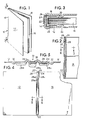
- a one-piece binder cover or assembly 10 which includes a front cover 12, a spine 14, and the back cover 16.
- a sheaf of loose papers 18, which may include text material, are positioned in the cover for binding along the left side edge as shown.
- the binder cover is cardboard and the paper 18 is a normal bond paper used for preparation of text or typed materials.
- a pair of spaced electrically conductive rivets 20 and 22 extend through the spine and contact the conductive layer 24 that is mounted to the spine by a paper, heat-insulating, pressure sensitive layer 26.
- a hot-melt or heat-activated adhesive layer 28 is carried on the conductive layer 24 between the rivets 20 and 22. All of these elements are within the binder and do not extend externally thereof. The sheaf of loose papers 18 is shown in the bound position.
- the binder cover 10 is shown in enlarged detail and is pressed to provide various score lines or depressions for hinging and bending.
- the depressions 30 and 32 permit the covers 12 and 16 to be opened or bent along the hinge connections made by the depressions.
- the individual sheets of paper 18 are shown bound to the spine and between the hinges. More particularly, the heat-activated adhesive layer 28 is shown in a melted condition in which adhesive has flowed between the sheets of the paper 18.
- the electrically conductive layer 24 is seen in engagement with the heat-activated adhesive on one side and the paper insulator backing 26 on the other side for securing the conductive layer to the binder.
- One of two spaced rivets 22 is shown, and it is understood that electrical current may pass from outside the binder through the conductive rivet 22 to the electrically conductive layer 24 for heating the heat-activated adhesive layer and then to the other rivet.
- the binder is shown in an open condition with covers 12 and 16 and spine 14.
- the rivets 20 and 22 are adjacent the top and bottom ends of the spine respectively and are spaced from one another.
- the heat-activated adhesive 28 is applied in three rows, a pair of outer rows 28a and 28c and a raised central row 28b between the rivets.
- the electrically conductive layer 24 is seen extending from rivet to rivet, as well as the larger insulator carrier 26 which carries the electrically conductive layer.
- the binder depressions 30 and 32 are also seen, as well as the spine-forming scores or protuberances 34 and 36.
- the heat-activated adhesive rows 28a, 28b and 28c are spaced from one another and positioned between the respective depressions and protuberances.
- the adhesive row 28c is positioned between depression 32 and protuberance 36.
- the conductive layer 24 is carried on the paper, heat-insulating layer 26.
- the outer adhesive rows 28a and 28c cover the outer edges of the conductive layer 24.
- the completed binder assembly is fabricated using the following steps: (1) the electrically conductive layer or ink is applied by screening onto the paper, heat insulating and pressure sensitive adhesive layer; (2) the screened ink-insulator/adhesive layer is adhered to the binder spine; (3) the various lines are scored into the cover to form the spine and hinges; (4) the hot melt adhesive is applied to the conductive ink; and (5) the spaced rivets are then fastened in place through the conductive layer, insulator/adhesive layer and binder.
- the paper layer 26 is a heat insulator and has a pressure sensitive backing.
- the conductive ink or conductive layer is applied to the non-adhesive side of the paper layer.
- One particular paper layer may be purchased from Fasson, an Avery International Company, 7670 Auburn Road, Painesville, Ohio, and is identified as 60# U.L. Litho/S-730/46# Fastrip.
- the conductive layer must conduct electricity and generate heat for melting and adhesive.
- the layer can be a film conductor or a conductive ink as, for example, the type purchased from the DuPont Company, Wilmington, Delaware, and identified as Polymeric Thick Film Materials for Circuitry, Conductor 5008. Other inks are available from other sources. This ink is screened onto or applied to the adhesive-backed paper insulator layer and the paper then adhered to the binder spine. This ink is useful for fabricating low voltage circuitry on flexible substrates. The important feature is that the ink is conductive and that it has resistance to generate sufficient heat for causing the adhesive 28 to flow.
- the heat-activated adhesive is selected on the basis that (1) at ambient temperatures it is fundamentally solid and will not flow, while (2) at elevated temperatures it will flow and be tacky and sticky. However, the adhesive must be activatable at a temperature less than the scorching temperature of paper so as to avoid any fires or the like resulting from overheating of the adhesive. Thus the desired minimum flow temperature is greater than ambient and the maximum temperature is less than the scorching temperature of paper.
- Heat-activated adhesives which are satisfactory include hot melt adhesives as sold by National Starch and Chemical Corporation, Finderne Avenue, P.O. Box 6500, Bridgewater, New Jersey 08807 and identified as Flex Back 34-1113.
- a sheaf of papers is positioned against the spine of the binder and an electrical current passed between the rivets 20 and 22 so that a current passes through the electrically conductive ink or layer 24, which in turn heats the hot melt adhesive 28, which flows in the paper edges so as to bind the edge of the papers 18 thereto.
- a temperature between 57°C (160°F) and 176°C (375°F) is acceptable.
Landscapes
- Heat Sensitive Colour Forming Recording (AREA)
- Package Frames And Binding Bands (AREA)
- Adhesive Tapes (AREA)
- Sheet Holders (AREA)
- Packaging For Recording Disks (AREA)
- Biological Depolymerization Polymers (AREA)
- Basic Packing Technique (AREA)
- Elimination Of Static Electricity (AREA)
- Laminated Bodies (AREA)
- Paper Feeding For Electrophotography (AREA)
Claims (11)
un dos et un plat de devant et un plat de derrière joints par charnière audit dos ;
une couche résistive conductrice de l'électricité appliquée le long du dos sur sa surface intérieure ;
une couche d'adhésif activable par la chaleur appliquée sur ladite couche résistive conductrice de l'électricité ; et
une paire de moyens de contact conducteurs de l'électricité espacés l'un de l'autre et s'étendant à travers ladite couche résistive conductrice de l'électricité et ladite reliure ; ladite couche résistive conductrice de l'électricité, ladite couche d'adhésif activable par la chaleur et lesdits moyens de contact se situant entre les limites de la longueur dudit dos.
Priority Applications (1)
| Application Number | Priority Date | Filing Date | Title |
|---|---|---|---|
| AT89104954T ATE78759T1 (de) | 1988-03-22 | 1989-03-20 | Decke und bindesystem. |
Applications Claiming Priority (2)
| Application Number | Priority Date | Filing Date | Title |
|---|---|---|---|
| US171767 | 1988-03-22 | ||
| US07/171,767 US4848797A (en) | 1988-03-22 | 1988-03-22 | Binder cover and binding system |
Publications (3)
| Publication Number | Publication Date |
|---|---|
| EP0334260A2 EP0334260A2 (fr) | 1989-09-27 |
| EP0334260A3 EP0334260A3 (en) | 1989-11-15 |
| EP0334260B1 true EP0334260B1 (fr) | 1992-07-29 |
Family
ID=22625051
Family Applications (1)
| Application Number | Title | Priority Date | Filing Date |
|---|---|---|---|
| EP89104954A Expired - Lifetime EP0334260B1 (fr) | 1988-03-22 | 1989-03-20 | Couverture et système de reliure |
Country Status (10)
| Country | Link |
|---|---|
| US (1) | US4848797A (fr) |
| EP (1) | EP0334260B1 (fr) |
| JP (1) | JPH0771877B2 (fr) |
| AT (1) | ATE78759T1 (fr) |
| AU (1) | AU615724B2 (fr) |
| CA (1) | CA1327502C (fr) |
| DE (1) | DE68902254T2 (fr) |
| ES (1) | ES2034448T3 (fr) |
| GR (1) | GR3005380T3 (fr) |
| MX (1) | MX166620B (fr) |
Families Citing this family (13)
| Publication number | Priority date | Publication date | Assignee | Title |
|---|---|---|---|---|
| US5250985A (en) * | 1990-10-29 | 1993-10-05 | Mita Industrial Co., Ltd. | Image forming apparatus equipped with a binding function |
| US5275520A (en) * | 1990-11-14 | 1994-01-04 | Mita Industrial Co., Ltd. | Binding unit for binding sheets in adherence to a binder |
| AU1075897A (en) * | 1995-11-13 | 1998-01-05 | Norbert John Durand | Binder assembly system employing special plastic spine |
| US6652210B1 (en) | 2000-02-25 | 2003-11-25 | Yeaple Corporation | Individual book-binding system and method |
| US7252472B1 (en) * | 2003-02-06 | 2007-08-07 | Yeaple Corporation | Individual bookbinding device, system, and associated methods |
| US6910842B1 (en) | 2003-02-06 | 2005-06-28 | Yeaple Corporation | Bookbinding machine and method for individual bookbinding system |
| US7354232B1 (en) | 2003-12-16 | 2008-04-08 | Yeaple Corporation | Individual bookbinding device, system, and associated methods |
| WO2005115764A2 (fr) | 2004-05-21 | 2005-12-08 | Esselte | Système de perforation et de reliure et ses éléments |
| BE1016204A3 (nl) * | 2004-09-20 | 2006-05-02 | Unibind Cyprus Ltd | Inbindelement. |
| BE1018813A3 (nl) * | 2009-07-07 | 2011-09-06 | Unibind Ltd | Werkwijze voor het inbinden van een bundel bladen en voorgevormde kaft daarbij toegepast. |
| US8517641B2 (en) * | 2009-07-21 | 2013-08-27 | Illinois Tool Works Inc. | Anchoring adhesive combination and integrated method of applying it |
| CA2842250C (fr) | 2011-07-18 | 2020-05-12 | ACCO Brands Corporation | Systeme de reliure pour retenir des composants relies |
| US10821767B1 (en) | 2019-10-29 | 2020-11-03 | Lo-Res Labs LLC | Binder with expandable spine |
Family Cites Families (10)
| Publication number | Priority date | Publication date | Assignee | Title |
|---|---|---|---|---|
| US1805314A (en) * | 1930-04-16 | 1931-05-12 | Mcbee Binder Company | Binder for loose leaf books |
| US1978754A (en) * | 1934-02-16 | 1934-10-30 | Maricnthal Paul | Loose-leaf book construction |
| US2097626A (en) * | 1934-12-26 | 1937-11-02 | Nat Blank Book Co | Book leaf securing means |
| US3840254A (en) * | 1972-06-15 | 1974-10-08 | Heller W | Perfect binding |
| US4019758A (en) * | 1973-02-26 | 1977-04-26 | William C. Heller, Jr. | Book binding process |
| US3964769A (en) * | 1973-05-23 | 1976-06-22 | William C. Heller, Jr. | Book binding method |
| US4141100A (en) * | 1976-09-27 | 1979-02-27 | Domroe William E | Binding machine and cover for use therewith |
| FR2509546A1 (fr) * | 1981-07-13 | 1983-01-14 | Kollmorgen Tech Corp | Appareil d'entrainement a moteur electrique |
| FR2546822B1 (fr) * | 1983-06-01 | 1986-09-26 | Akopian Georges | Couverture permettant d'effectuer la reliure de feuilles volantes et appareil de mise en oeuvre |
| US4855573A (en) * | 1988-03-22 | 1989-08-08 | General Binding Corporation | Electrically heated binder apparatus |
-
1988
- 1988-03-22 US US07/171,767 patent/US4848797A/en not_active Expired - Fee Related
-
1989
- 1989-03-20 AT AT89104954T patent/ATE78759T1/de not_active IP Right Cessation
- 1989-03-20 EP EP89104954A patent/EP0334260B1/fr not_active Expired - Lifetime
- 1989-03-20 ES ES198989104954T patent/ES2034448T3/es not_active Expired - Lifetime
- 1989-03-20 DE DE8989104954T patent/DE68902254T2/de not_active Expired - Fee Related
- 1989-03-21 CA CA000594290A patent/CA1327502C/fr not_active Expired - Fee Related
- 1989-03-21 AU AU31565/89A patent/AU615724B2/en not_active Ceased
- 1989-03-22 MX MX015373A patent/MX166620B/es unknown
- 1989-03-22 JP JP1070288A patent/JPH0771877B2/ja not_active Expired - Lifetime
-
1992
- 1992-08-06 GR GR920401715T patent/GR3005380T3/el unknown
Also Published As
| Publication number | Publication date |
|---|---|
| EP0334260A3 (en) | 1989-11-15 |
| JPH0270496A (ja) | 1990-03-09 |
| US4848797A (en) | 1989-07-18 |
| EP0334260A2 (fr) | 1989-09-27 |
| ATE78759T1 (de) | 1992-08-15 |
| ES2034448T3 (es) | 1993-04-01 |
| JPH0771877B2 (ja) | 1995-08-02 |
| AU615724B2 (en) | 1991-10-10 |
| MX166620B (es) | 1993-01-22 |
| DE68902254T2 (de) | 1993-01-07 |
| GR3005380T3 (fr) | 1993-05-24 |
| CA1327502C (fr) | 1994-03-08 |
| DE68902254D1 (de) | 1992-09-03 |
| AU3156589A (en) | 1989-09-28 |
Similar Documents
| Publication | Publication Date | Title |
|---|---|---|
| EP0334260B1 (fr) | Couverture et système de reliure | |
| US4380315A (en) | Mailer | |
| EP0540242B1 (fr) | Adhésifs thermorésistants pour adhérer les fenêtres des formulaires commerciaux | |
| EP0796744B1 (fr) | Classeur avec porte-étiquette | |
| WO1993002867A1 (fr) | Procede de reliure de documents | |
| HUT53837A (en) | Universal fastening element for attaching documents consist of pages | |
| JP2000203174A5 (fr) | ||
| CN1042509C (zh) | 装订元件 | |
| US4552479A (en) | Easel type binder | |
| WO1984002496A1 (fr) | Feuille reliable prefabriquee et procede et dispositif de reliure | |
| JPS58500656A (ja) | ソフトカバ−ブツクとその製造法 | |
| US4371194A (en) | Universal binding for making variable sized books and reports | |
| US4371195A (en) | Cover with adhesive bridges in scored areas | |
| IE41165L (en) | Binding for paper sheets | |
| US1973989A (en) | Fastening device for flat articles | |
| JP3602236B2 (ja) | 紙片を綴じる部品 | |
| US5035447A (en) | Binding element for binding loose sheets in a file | |
| US7354232B1 (en) | Individual bookbinding device, system, and associated methods | |
| ATE52061T1 (de) | Einband fuer papierblaetter. | |
| US6910842B1 (en) | Bookbinding machine and method for individual bookbinding system | |
| US5167998A (en) | Postcards and reply postcards for confidential purposes | |
| CA1336611C (fr) | Enveloppe | |
| US4896821A (en) | Envelopes | |
| US6139209A (en) | System for binding printed works | |
| EP0723877A2 (fr) | Bloc-notes |
Legal Events
| Date | Code | Title | Description |
|---|---|---|---|
| PUAI | Public reference made under article 153(3) epc to a published international application that has entered the european phase |
Free format text: ORIGINAL CODE: 0009012 |
|
| AK | Designated contracting states |
Kind code of ref document: A2 Designated state(s): AT BE CH DE ES FR GB GR IT LI LU NL SE |
|
| PUAL | Search report despatched |
Free format text: ORIGINAL CODE: 0009013 |
|
| AK | Designated contracting states |
Kind code of ref document: A3 Designated state(s): AT BE CH DE ES FR GB GR IT LI LU NL SE |
|
| 17P | Request for examination filed |
Effective date: 19900418 |
|
| 17Q | First examination report despatched |
Effective date: 19911021 |
|
| GRAA | (expected) grant |
Free format text: ORIGINAL CODE: 0009210 |
|
| AK | Designated contracting states |
Kind code of ref document: B1 Designated state(s): AT BE CH DE ES FR GB GR IT LI LU NL SE |
|
| REF | Corresponds to: |
Ref document number: 78759 Country of ref document: AT Date of ref document: 19920815 Kind code of ref document: T |
|
| REF | Corresponds to: |
Ref document number: 68902254 Country of ref document: DE Date of ref document: 19920903 |
|
| ITF | It: translation for a ep patent filed | ||
| ET | Fr: translation filed | ||
| REG | Reference to a national code |
Ref country code: GR Ref legal event code: FG4A Free format text: 3005380 |
|
| REG | Reference to a national code |
Ref country code: ES Ref legal event code: FG2A Ref document number: 2034448 Country of ref document: ES Kind code of ref document: T3 |
|
| PLBE | No opposition filed within time limit |
Free format text: ORIGINAL CODE: 0009261 |
|
| STAA | Information on the status of an ep patent application or granted ep patent |
Free format text: STATUS: NO OPPOSITION FILED WITHIN TIME LIMIT |
|
| 26N | No opposition filed | ||
| PGFP | Annual fee paid to national office [announced via postgrant information from national office to epo] |
Ref country code: GR Payment date: 19940119 Year of fee payment: 6 |
|
| PGFP | Annual fee paid to national office [announced via postgrant information from national office to epo] |
Ref country code: AT Payment date: 19940131 Year of fee payment: 6 |
|
| PGFP | Annual fee paid to national office [announced via postgrant information from national office to epo] |
Ref country code: LU Payment date: 19940228 Year of fee payment: 6 |
|
| PGFP | Annual fee paid to national office [announced via postgrant information from national office to epo] |
Ref country code: SE Payment date: 19940314 Year of fee payment: 6 |
|
| EPTA | Lu: last paid annual fee | ||
| PGFP | Annual fee paid to national office [announced via postgrant information from national office to epo] |
Ref country code: BE Payment date: 19950103 Year of fee payment: 7 |
|
| PGFP | Annual fee paid to national office [announced via postgrant information from national office to epo] |
Ref country code: CH Payment date: 19950124 Year of fee payment: 7 |
|
| PGFP | Annual fee paid to national office [announced via postgrant information from national office to epo] |
Ref country code: FR Payment date: 19950125 Year of fee payment: 7 |
|
| EAL | Se: european patent in force in sweden |
Ref document number: 89104954.6 |
|
| PGFP | Annual fee paid to national office [announced via postgrant information from national office to epo] |
Ref country code: ES Payment date: 19950307 Year of fee payment: 7 |
|
| PG25 | Lapsed in a contracting state [announced via postgrant information from national office to epo] |
Ref country code: LU Free format text: LAPSE BECAUSE OF NON-PAYMENT OF DUE FEES Effective date: 19950320 Ref country code: AT Effective date: 19950320 |
|
| PG25 | Lapsed in a contracting state [announced via postgrant information from national office to epo] |
Ref country code: SE Effective date: 19950321 |
|
| PGFP | Annual fee paid to national office [announced via postgrant information from national office to epo] |
Ref country code: NL Payment date: 19950331 Year of fee payment: 7 |
|
| PG25 | Lapsed in a contracting state [announced via postgrant information from national office to epo] |
Ref country code: GR Free format text: THE PATENT HAS BEEN ANNULLED BY A DECISION OF A NATIONAL AUTHORITY Effective date: 19950930 |
|
| REG | Reference to a national code |
Ref country code: GR Ref legal event code: MM2A Free format text: 3005380 |
|
| EUG | Se: european patent has lapsed |
Ref document number: 89104954.6 |
|
| PG25 | Lapsed in a contracting state [announced via postgrant information from national office to epo] |
Ref country code: ES Free format text: LAPSE BECAUSE OF NON-PAYMENT OF DUE FEES Effective date: 19960321 |
|
| PG25 | Lapsed in a contracting state [announced via postgrant information from national office to epo] |
Ref country code: LI Effective date: 19960331 Ref country code: CH Effective date: 19960331 Ref country code: BE Effective date: 19960331 |
|
| PGFP | Annual fee paid to national office [announced via postgrant information from national office to epo] |
Ref country code: DE Payment date: 19960613 Year of fee payment: 8 |
|
| PGFP | Annual fee paid to national office [announced via postgrant information from national office to epo] |
Ref country code: GB Payment date: 19960617 Year of fee payment: 8 |
|
| BERE | Be: lapsed |
Owner name: GENERAL BINDING CORP. Effective date: 19960331 |
|
| PG25 | Lapsed in a contracting state [announced via postgrant information from national office to epo] |
Ref country code: NL Effective date: 19961001 |
|
| REG | Reference to a national code |
Ref country code: CH Ref legal event code: PL |
|
| PG25 | Lapsed in a contracting state [announced via postgrant information from national office to epo] |
Ref country code: FR Effective date: 19961129 |
|
| NLV4 | Nl: lapsed or anulled due to non-payment of the annual fee |
Effective date: 19961001 |
|
| REG | Reference to a national code |
Ref country code: FR Ref legal event code: ST |
|
| PG25 | Lapsed in a contracting state [announced via postgrant information from national office to epo] |
Ref country code: GB Effective date: 19970320 |
|
| GBPC | Gb: european patent ceased through non-payment of renewal fee |
Effective date: 19970320 |
|
| PG25 | Lapsed in a contracting state [announced via postgrant information from national office to epo] |
Ref country code: DE Effective date: 19971202 |
|
| REG | Reference to a national code |
Ref country code: ES Ref legal event code: FD2A Effective date: 19990405 |
|
| PG25 | Lapsed in a contracting state [announced via postgrant information from national office to epo] |
Ref country code: IT Free format text: LAPSE BECAUSE OF NON-PAYMENT OF DUE FEES;WARNING: LAPSES OF ITALIAN PATENTS WITH EFFECTIVE DATE BEFORE 2007 MAY HAVE OCCURRED AT ANY TIME BEFORE 2007. THE CORRECT EFFECTIVE DATE MAY BE DIFFERENT FROM THE ONE RECORDED. Effective date: 20050320 |