EP0334263A1 - Blindage pour prévenir le phénomène d'écaillage - Google Patents
Blindage pour prévenir le phénomène d'écaillage Download PDFInfo
- Publication number
- EP0334263A1 EP0334263A1 EP89104961A EP89104961A EP0334263A1 EP 0334263 A1 EP0334263 A1 EP 0334263A1 EP 89104961 A EP89104961 A EP 89104961A EP 89104961 A EP89104961 A EP 89104961A EP 0334263 A1 EP0334263 A1 EP 0334263A1
- Authority
- EP
- European Patent Office
- Prior art keywords
- spall
- backing material
- armor
- metal
- impedance
- Prior art date
- Legal status (The legal status is an assumption and is not a legal conclusion. Google has not performed a legal analysis and makes no representation as to the accuracy of the status listed.)
- Granted
Links
- 230000001629 suppression Effects 0.000 title claims abstract description 25
- 239000000463 material Substances 0.000 claims abstract description 247
- 229910052751 metal Inorganic materials 0.000 claims abstract description 63
- 239000002184 metal Substances 0.000 claims abstract description 63
- 239000002245 particle Substances 0.000 claims abstract description 61
- 239000000843 powder Substances 0.000 claims abstract description 40
- 239000011159 matrix material Substances 0.000 claims abstract description 32
- 230000035515 penetration Effects 0.000 claims abstract description 31
- 239000012634 fragment Substances 0.000 claims abstract description 16
- 239000002131 composite material Substances 0.000 claims description 58
- 229910052782 aluminium Inorganic materials 0.000 claims description 52
- XAGFODPZIPBFFR-UHFFFAOYSA-N aluminium Chemical compound [Al] XAGFODPZIPBFFR-UHFFFAOYSA-N 0.000 claims description 52
- 229920006231 aramid fiber Polymers 0.000 claims description 30
- 238000000034 method Methods 0.000 claims description 30
- 230000035939 shock Effects 0.000 claims description 26
- 229920000642 polymer Polymers 0.000 claims description 23
- 239000006185 dispersion Substances 0.000 claims description 19
- 229920002379 silicone rubber Polymers 0.000 claims description 18
- WFKWXMTUELFFGS-UHFFFAOYSA-N tungsten Chemical compound [W] WFKWXMTUELFFGS-UHFFFAOYSA-N 0.000 claims description 17
- 229910000831 Steel Inorganic materials 0.000 claims description 15
- 238000004519 manufacturing process Methods 0.000 claims description 15
- 239000010959 steel Substances 0.000 claims description 15
- 239000004593 Epoxy Substances 0.000 claims description 14
- RYGMFSIKBFXOCR-UHFFFAOYSA-N Copper Chemical group [Cu] RYGMFSIKBFXOCR-UHFFFAOYSA-N 0.000 claims description 13
- 230000015572 biosynthetic process Effects 0.000 claims description 13
- 239000004945 silicone rubber Substances 0.000 claims description 13
- 239000010949 copper Substances 0.000 claims description 11
- 229910052721 tungsten Inorganic materials 0.000 claims description 11
- 239000010937 tungsten Substances 0.000 claims description 11
- 229910052802 copper Inorganic materials 0.000 claims description 10
- 239000010935 stainless steel Substances 0.000 claims description 10
- 229910001220 stainless steel Inorganic materials 0.000 claims description 10
- 239000000853 adhesive Substances 0.000 claims description 9
- 230000001070 adhesive effect Effects 0.000 claims description 9
- 239000000835 fiber Substances 0.000 claims description 8
- 231100000518 lethal Toxicity 0.000 claims description 8
- 230000001665 lethal effect Effects 0.000 claims description 8
- 230000000149 penetrating effect Effects 0.000 claims description 6
- 229920001971 elastomer Polymers 0.000 claims description 5
- 239000000806 elastomer Substances 0.000 claims description 5
- 229920000647 polyepoxide Polymers 0.000 claims description 5
- 230000003247 decreasing effect Effects 0.000 claims description 4
- 239000011152 fibreglass Substances 0.000 claims description 4
- 231100001160 nonlethal Toxicity 0.000 claims description 4
- 230000004044 response Effects 0.000 claims description 4
- 229910000906 Bronze Inorganic materials 0.000 claims description 3
- 239000010974 bronze Substances 0.000 claims description 3
- KUNSUQLRTQLHQQ-UHFFFAOYSA-N copper tin Chemical compound [Cu].[Sn] KUNSUQLRTQLHQQ-UHFFFAOYSA-N 0.000 claims description 3
- 238000013016 damping Methods 0.000 claims description 3
- 239000007787 solid Substances 0.000 claims description 3
- 229910052596 spinel Inorganic materials 0.000 claims description 3
- 229910000851 Alloy steel Inorganic materials 0.000 claims description 2
- CPLXHLVBOLITMK-UHFFFAOYSA-N Magnesium oxide Chemical compound [Mg]=O CPLXHLVBOLITMK-UHFFFAOYSA-N 0.000 claims description 2
- 231100000053 low toxicity Toxicity 0.000 claims description 2
- 239000011029 spinel Substances 0.000 claims description 2
- 238000005303 weighing Methods 0.000 claims 7
- 239000003822 epoxy resin Substances 0.000 claims 1
- 230000001747 exhibiting effect Effects 0.000 claims 1
- 238000012856 packing Methods 0.000 claims 1
- 239000012255 powdered metal Substances 0.000 claims 1
- UONOETXJSWQNOL-UHFFFAOYSA-N tungsten carbide Chemical compound [W+]#[C-] UONOETXJSWQNOL-UHFFFAOYSA-N 0.000 claims 1
- 239000000919 ceramic Substances 0.000 abstract description 12
- 239000010410 layer Substances 0.000 description 42
- 238000012360 testing method Methods 0.000 description 40
- 239000002356 single layer Substances 0.000 description 16
- PNEYBMLMFCGWSK-UHFFFAOYSA-N aluminium oxide Inorganic materials [O-2].[O-2].[O-2].[Al+3].[Al+3] PNEYBMLMFCGWSK-UHFFFAOYSA-N 0.000 description 14
- 230000003993 interaction Effects 0.000 description 12
- 238000005755 formation reaction Methods 0.000 description 10
- 238000009826 distribution Methods 0.000 description 8
- 230000000694 effects Effects 0.000 description 7
- 230000009467 reduction Effects 0.000 description 7
- FAPWRFPIFSIZLT-UHFFFAOYSA-M Sodium chloride Chemical compound [Na+].[Cl-] FAPWRFPIFSIZLT-UHFFFAOYSA-M 0.000 description 6
- 230000001419 dependent effect Effects 0.000 description 6
- 238000013461 design Methods 0.000 description 6
- 239000002360 explosive Substances 0.000 description 6
- 239000011229 interlayer Substances 0.000 description 6
- 101100465853 Caenorhabditis elegans psf-2 gene Proteins 0.000 description 5
- 229910045601 alloy Inorganic materials 0.000 description 5
- 239000000956 alloy Substances 0.000 description 5
- 230000006378 damage Effects 0.000 description 5
- 230000008901 benefit Effects 0.000 description 4
- 238000005474 detonation Methods 0.000 description 4
- 125000003700 epoxy group Chemical group 0.000 description 4
- 239000011151 fibre-reinforced plastic Substances 0.000 description 4
- 239000000945 filler Substances 0.000 description 4
- 230000007246 mechanism Effects 0.000 description 4
- 238000004364 calculation method Methods 0.000 description 3
- 230000008030 elimination Effects 0.000 description 3
- 238000003379 elimination reaction Methods 0.000 description 3
- 230000008569 process Effects 0.000 description 3
- 239000011780 sodium chloride Substances 0.000 description 3
- 229920002430 Fibre-reinforced plastic Polymers 0.000 description 2
- 238000007792 addition Methods 0.000 description 2
- 238000004458 analytical method Methods 0.000 description 2
- 239000011230 binding agent Substances 0.000 description 2
- 239000000969 carrier Substances 0.000 description 2
- 229910010293 ceramic material Inorganic materials 0.000 description 2
- 238000010586 diagram Methods 0.000 description 2
- 239000000446 fuel Substances 0.000 description 2
- 239000011521 glass Substances 0.000 description 2
- 230000003116 impacting effect Effects 0.000 description 2
- 150000002739 metals Chemical class 0.000 description 2
- 229920002959 polymer blend Polymers 0.000 description 2
- 239000011163 secondary particle Substances 0.000 description 2
- 239000013077 target material Substances 0.000 description 2
- 229910000881 Cu alloy Inorganic materials 0.000 description 1
- 235000009854 Cucurbita moschata Nutrition 0.000 description 1
- 240000001980 Cucurbita pepo Species 0.000 description 1
- 235000009852 Cucurbita pepo Nutrition 0.000 description 1
- 229910026161 MgAl2O4 Inorganic materials 0.000 description 1
- 239000004677 Nylon Substances 0.000 description 1
- 208000027418 Wounds and injury Diseases 0.000 description 1
- 238000002679 ablation Methods 0.000 description 1
- 238000010521 absorption reaction Methods 0.000 description 1
- 238000013459 approach Methods 0.000 description 1
- 239000004760 aramid Substances 0.000 description 1
- 229920003235 aromatic polyamide Polymers 0.000 description 1
- 230000005540 biological transmission Effects 0.000 description 1
- 229910002114 biscuit porcelain Inorganic materials 0.000 description 1
- 238000005266 casting Methods 0.000 description 1
- 230000008859 change Effects 0.000 description 1
- 238000004590 computer program Methods 0.000 description 1
- 238000011161 development Methods 0.000 description 1
- 230000018109 developmental process Effects 0.000 description 1
- 238000007599 discharging Methods 0.000 description 1
- 239000013013 elastic material Substances 0.000 description 1
- 238000011156 evaluation Methods 0.000 description 1
- 239000000284 extract Substances 0.000 description 1
- 239000004744 fabric Substances 0.000 description 1
- 239000010419 fine particle Substances 0.000 description 1
- 238000013467 fragmentation Methods 0.000 description 1
- 238000006062 fragmentation reaction Methods 0.000 description 1
- 235000019589 hardness Nutrition 0.000 description 1
- 229920001903 high density polyethylene Polymers 0.000 description 1
- 230000006872 improvement Effects 0.000 description 1
- 238000007373 indentation Methods 0.000 description 1
- 230000000977 initiatory effect Effects 0.000 description 1
- 208000014674 injury Diseases 0.000 description 1
- 230000002452 interceptive effect Effects 0.000 description 1
- 231100000225 lethality Toxicity 0.000 description 1
- 239000000203 mixture Substances 0.000 description 1
- 230000004048 modification Effects 0.000 description 1
- 238000012986 modification Methods 0.000 description 1
- 230000006911 nucleation Effects 0.000 description 1
- 238000010899 nucleation Methods 0.000 description 1
- 229920001778 nylon Polymers 0.000 description 1
- 239000011368 organic material Substances 0.000 description 1
- 239000004014 plasticizer Substances 0.000 description 1
- 239000002861 polymer material Substances 0.000 description 1
- 230000002265 prevention Effects 0.000 description 1
- 230000003014 reinforcing effect Effects 0.000 description 1
- 238000004088 simulation Methods 0.000 description 1
- 238000004901 spalling Methods 0.000 description 1
- 238000005507 spraying Methods 0.000 description 1
- 235000020354 squash Nutrition 0.000 description 1
- 238000006467 substitution reaction Methods 0.000 description 1
- 230000033772 system development Effects 0.000 description 1
- 239000000454 talc Substances 0.000 description 1
- 229920001169 thermoplastic Polymers 0.000 description 1
- 239000004634 thermosetting polymer Substances 0.000 description 1
Images


Classifications
-
- F—MECHANICAL ENGINEERING; LIGHTING; HEATING; WEAPONS; BLASTING
- F41—WEAPONS
- F41H—ARMOUR; ARMOURED TURRETS; ARMOURED OR ARMED VEHICLES; MEANS OF ATTACK OR DEFENCE, e.g. CAMOUFLAGE, IN GENERAL
- F41H5/00—Armour; Armour plates
- F41H5/02—Plate construction
- F41H5/04—Plate construction composed of more than one layer
Definitions
- the present invention is an improvement over that disclosed in Musante et al Application Serial No. 098,633 filed September 18, 1987 entitled ACTIVE SPALL SUPPRESSION ARMOR. (European Application 88 113 787.1)
- the present invention relates to the reduction of injury and damage from the spall typically generated off the inside surface of armor plate or the like, by contiguously attaching light weight spall backing material having a sonic impedance such that the stress reflected into the armor is below that which causes significant spallation in the armor.
- the lightweight backing is frangible or of low strength such that when it fractures, the particles are of low mass and/or kinetic energy and of minimal concentration capability.
- Spall is a primary cause of armor vehicle kills during combat. Spall may be characterized as a cloud of high velocity fragments of metal which is released from the inside surface of the vehicle's armored hull and is lethal to soft targets inside the vehicle.
- the soft targets include electrical cables, electrical components, fuel lines, fuel cells, and personnel within the vehicle.
- Spall liners consisting of aramid fiber reinforced polymer panels are currently being used for minimizing the spall effect, but are quite expensive and heavy. Application of these liners is hindered by limited space in vehicles and the low space efficiency of the liners. The effectiveness of these liners require that the liners be spaced from typically about 4 to 17 inches from the inner wall of the vehicle and are therefore undesirable since the useable space within most vehicles is quite limited. Also, the hardware within the vehicles makes it difficult or impossible to secure the liner within all portions of the vehicle without interfering with the operation and location of vehicle components. Significant areas in vehicles, such as turret and driver areas, have spall protection which is either limited or non-existent due to lack of space for any standoff.
- active spall suppression armor includes an armor material or plate backed by a spall backing material which is contiguously attached to the inside surface of the armor, typically by adhesives.
- the spall backing material may be of the consistency of pliable putty, or may be in the form of hard, soft, or elastic tiles or sheets.
- the matrix binder may serve to contiguously adhere the backing material to the armor. The spall material when fractured, due to stresses transmitted through the armor material, forms nonlethal fragments of low mass and kinetic energy.
- the sonic impedance of the spall material is such that the stress reflected by the spall backing material into the armor is below that which causes failure in the armor, which failure would result in lethal spall particles being propelled from the inner surface of the metal armor. Spall may be created in the backing material but the effect is minimized by assuring that the spall created in the backing material has low energy and is therefore of limited penetration capability.
- the armor material may be steel armor, aluminum armor, and other types of armor including composite materials.
- the improved active spall suppression armor is directed to the use of different types of either monolithic or composite materials in contact with the armor plate, used alone or with a secondary layer or plate spaced therefrom.
- the improved active spall suppression system performs better than present spall liners where minimal space is available, typically under four inches.
- Figure 1 diagrammatically illustrates a section of metal armor 20, without a spall backing material attached thereto, being contacted by a weapon 22 which may be a shaped charge or a high velocity projectile.
- the weapon 22 contacts an outer surface 23 of the armor with sufficient force to dislodge spall fragments 24 from the free or inner surface 26 of the armor 20.
- the spall fragments are propelled from the inner surface 26 of the armor along a conical path of about 100° at high velocity with many of the fragments being of sufficient mass to be highly penetrating to soft targets that are contacted by the fragments. More particularly, spalling is a failure mode wherein fracture occurs near the free surface 26 (Fig. 1) remote from the outer surface 23 where an impulse load is applied.
- the impulse load is typically generated by an explosive detonation from a shaped charge, or by the impact of a high velocity projectile.
- the impulse induces a compressive shock wave which propagates to the opposite free surface 26 where it reflects as a tensile wave.
- the intensity of the tensile wave will increase as it propagates back through the material. At some distance from the surface 26, the stress intensity exceeds the threshold required for initiation and fracture at which time spallation occurs discharging the spall 24 inwardly at high velocity.
- Figure 2 diagrammatically illustrates a vertical section through two armor plate walls 28,29 of a vehicle having two prior art spall liners 32,34 spaced inwardly of the vehicle.
- the path 36 of the projectile is illustrated by arrows as passing through both walls 28,29 and liners 32,34.
- a primary spall cone angle in the first contacted wall 28 indicates that the first spall liner 32 stops some spall but allows larger high velocity pieces to pass through and be stopped by a second spall liner 34 as illustrated by a narrow secondary spall cone 38.
- Figure 4 represents stresses caused by shaped charge weapons and illustrates the formation of compressive and tensile waves when passing through the first contacted armor at four separate time intervals to the free surface 26 without spall backing material attached thereto.
- a saw-tooth wave or pulse 39 illustrates the stress intensity relative to the back or inner surface 26 of the armor caused by the detonation of an explosive.
- the compressive wave 39 reaches the free surface 26 it reflects as a tensile wave 42, which is partially cancelled by the incident compressive pulse 39.
- the tensile stress will increase until the maximum stress occurs at a distance from the surface 26 of the plate 20 equal to one-half of the pulse length as indicated at time T-3.
- the intensity of the tensile wave exceeds the compressive wave thus indicating that spall will not be created.
- the stress waves behavior becomes more complex.
- the simplest situation is a normal impact by a projectile with a diameter of the same order of magnitude as the armor plate thickness.
- the stress wave can then be considered to have a planar front and to travel perpendicular to the face of the plate.
- this wave reaches an interface, one wave is reflected and another is transmitted.
- the intensities of the waves are dependent upon the relative sonic impedances of the two materials.
- the sonic impedance (Z) of a material is the product of the sound speed (c) in the material, and its density (D).
- the values of density and sound speed are not constant, but vary to some degree with pressure. Consequently, impedance can vary with the pressure and will definitely change when the yield strength of a material is exceeded. Generally, for most fully dense, elastic materials, the impedance below the yield point is relatively constant.
- the density, sound speed, and impedance are listed in Table 1 for a number of common materials.
- the intensities of the transmitted and reflected waves from a stress wave impinging an internal interface are given by the following equations:
- compressive stress has a positive value and tensile stress has a negative value.
- a compressive wave will reflect as a tensile wave in the armor material if the second layer or backing material has a lower impedance, as illustrated in Figure 5A; and as a compressive wave if the backing material has a higher impedance as illustrated in Figure 5B.
- the amplitude of the reflected tensile wave will always be less than or equal to that of the incident compressive wave.
- the relative intensity of the reflected wave in the armor material is related to the relative impedance of the spall backing material as follows:
- n Z2/Z1.
- This ratio is tabulated in Table 2 to illustrate how a second layer, or backing material 40 (Fig. 6), can be used to reduce the magnitude of the reflected stress. It can be seen that a material with only one-fifth of the impedance of the first layer (armor material) can reduce the reflected tensile stress by as much as 33 percent. TABLE 2 Reduction in the reflected tensile stress for a given relative impedance of a layer of backing material. Impedance Ratio n % Reduction in Reflected Tensile Stress .10 18 .20 33 .30 46 .40 57 .50 67 .60 75 .70 82 .80 89 .90 95 1.00 100
- the spall backing material is not designed to completely suppress fractures in the spall backing material 40 by all known weapons but is designed to provide backing material which, if fractured, will fracture into low energy, particles of low penetration capability when the armored plate and backing material are contacted by a weapon, either a shaped charge weapon or a projectile. It is, of course, understood that the backing material may be thickened or be in layers of the same or different backing materials if added weight is not a problem.
- the concept of the subject invention involves the backing of armor plate 20 with a backing material 40, or a series of backing materials, which must satisfy two conditions.
- the impedance of the backing material must be such that the stress reflected into the armor plate 20 is below that which would cause spall-type failure in the armor plate.
- the fragments from the fracture of the backing material, caused by transmitted stress must be nonlethal, that is, of low mass and/or velocity. Varying impedance in the backing material may be used to condition the stress wave in the backing material to control fragmentation.
- the impedance may be varied by either layering or by controlling the material properties continuously through their thicknesses.
- a preliminary design analysis was made for identifying the relationship between design variables and system weights.
- the amount of the stress wave which must be transmitted into the spall backing material was estimated by comparing spall strength to the stresses involved in jet penetration. With this data, the properties of the spall backing material was determined.
- the weapons used were shaped charge TOW-II with a jet impacting aluminum armor.
- a 2009 GPa (giga pascals ) shock stress was generated with a pulse time length of 1.175 microseconds, which shock stress was calculated from the jet diameter divided by the sound speed in 5083 for MIL-A-46027G(MR) aluminum having a thickness of one inch. It was assumed that the aluminum had about the same spall "strength" as steel, the stress is so much higher in the aluminum than its strength, that essentially the full amplitude of the stress wave must be transmitted into the backing material.
- This design methodology also suggests the merits of a metallic or ceramic particle loaded polymer.
- the individual particles may have a higher sonic impedance than that of the armor.
- the particle content must be sufficient to insure that the particle/polymer blend has an impedance value sufficient to reduce the reflected tensile stress below that required to form spall.
- a particle/polymer blend may also afford the advantage of sticking directly to the armor without the need of an intermediate adhesive.
- a low density strength solid which fractures in a brittle manner, and which has a suitable impedance, may also be used.
- solid, polycrystalline sodium chloride (NaCl) in a 1/2 inch thickness has suppressed spall formation in aluminum armor when bonded to the back of the armor plate.
- the general procedure consists of adhesively bonding the backing material 40 (Fig. 6) to the armor plate 20 which together comprise a piece of active spall suppressive armor 18 in the form of a target 50 (Fig. 3).
- the target is fixed to a test stand 52, and the target 50 and a witness sheet 54 are subjected to a warhead attack.
- Base line targets of unbacked and liner-backed armor plates were also tested for comparison purposes.
- the witness sheets 54 were placed behind the test stand to record the distribution of spall and jet particles.
- the improved active spall suppression armor of the present invention discloses two systems for suppressing the formation of spall.
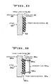
- a first system is a single layer system 80 (Fig. 8) which uses a single layer (or two or more thin plates to make up the single layer) of several preselected types of spall backing material 82 that is preferably bonded to the inner wall 84 of armor plate 86 (sometimes referred to as the target) by an interlayer 88 of adhesive.
- the material used to form the spall backing system differs from those previously described and provides improved spall suppression with spall backing materials of reduced weight.
- the second system is a double layer system 90 (Fig. 9) which bonds the same type of spall backing material 82a to the armor plate 86a by an interlayer 88a of adhesive.
- the second system includes a second plate or liner 92a spaced from the spall backing material 80a for defeating secondary particles of the jet and armor which are disturbed from the penetration interface by the presence of the active spall suppression backing.
- the primary spall backing material 82 is placed in contact with the armor plate 86 and may be bonded thereto if desired by the interlayer 88 of adhesive.
- the tacky nature of the polymer matrix of the backing material may be used as an adhesive if applied to the backing material before it is cured.
- the backing material may be sprayed or troweled onto the armor plate.
- the polymer matrix backing material may be cast into plates, allowed to cure, and thereafter be bolted to the armor plate 86.
- the spall backing material is formed of materials such that the composite backing was an impedance which is tailored so that the tensile stress is reduced below that required for spall formation. The spall backing material breaks up into fine, low energy, non-penetrating fragments after absorbing the shock wave.
- spall backing materials tested in the cross-referenced co-pending application were primarily alumina-type ceramics, whereas the spall backing material of the present invention are primarily metal and ceramic powder loaded polymer composites.
- the present state-of-the-art method for prevention of damage from spall is to place aramid fiber reinforced plastic liners (sometimes referred to as panels or plates) behind the armor in order to catch the spall particles.
- aramid fiber reinforced plastic liners sometimes referred to as panels or plates
- the space aspects are especially important in that internal volume is very limited in most light and all heavy armored combat vehicles.
- the liners are sometimes mounted 16 inches off the inner surface of the armor plate on a sliding rail system (for access behind the liners) whose weight equals that of the liner panels.
- a four inch standoff is used for most applications in the fighting vehicle, which limits efficiency. it would be very desirable to regain some or all of this lost volume without a loss of protection.
- the primary spall backing material 82 (Fig. 8) and 82a (Fig. 9) is placed in contact with the armor and has an impedance which is tailored such that the reflected tensile stress is reduced below that required for spall formation.
- This backing material breaks up into fine, low-energy, nonpenetrating fragments after absorbing the shock wave.
- This material preferably consists of metal powder filled polymers but the metal powders may be mixed with ceramic and glass powders, or fibers and whiskers.
- a relatively light secondary plate 92a (Fig. 9) of different material, spaced one or two inches from the armor 86a, may be used to fully suppress secondary particles of disrupted jet and armor. This system 90 has demonstrated improved performance at short stand-off spaces compared to prior art liners.
- spall can be characterized as a cloud of high velocity fragments of fractured material ejected from the back surface of an armor plate 86 (Fig. 8) due to impulse loading on the front surface of the plate.
- the impulse typically results from the impact of a high velocity projectile or a shaped charge jet and its slug as indicated by the attack arrow 94 in Figure 8.
- the impulse induces a compressive shock wave which propagates through the armor plate 86, and reflects from the rear free surface as a tensile wave.
- the reflected tensile wave superimposes with the incident compressive wave until at some distance from the back surface the tensile stress rises to a level sufficient to cause nucleation and growth of fracture.
- the strain energy remaining in the material between the fracture plane and the back surface is released as kinetic energy and the spall particles are ejected with significant kinetic energy.
- a shock wave interacts with an interface, such as interlayer 88, between two materials the situation is considerably more complex.
- an interface such as interlayer 88
- the intensity and sign (tensile or compressive) of the transmitted and reflected waves are a function of the sonic impedance of the material (the impedance is the product of the density and sound speed of the material).
- the relative intensity of the reflective wave compared to the incident wave can be expressed as a function of the relative impedance of the backing material 82 compared to that of the armor plate 86.
- the impedance ratio (n) is determined by the following formula where Z1 is the sonic impedance of the armor plate 86, where Z2 is the sonic impedance of the backing material, where the subscript r and i refer to the reflected and incident wave, and where the letter "a" refers to the stress amplitude.
- the backing material of the present invention is a frangible or low strength backing, which subsequent to suppression of spall in the armor, fractures into particles of low mass and/or velocity and low penetration capability.
- the requirements for backing material 82,82a are then: 1) the impedance of the backing material must be such that the stress reflected into the armor is below that which would cause armor spall; and 2) the fragments from the fracture of the backing material (caused by the transmitted stress) must have low penetration capacity.
- the double layer system 90 when using aluminum armor, with a two inch space, has demonstrated nominally equivalent performance, at lower weight, compared to the aramid fiber system in contact or with a four inch space.
- the powder loaded composites are the materials of choice for two major reasons. First, they yield reduced dispersion of the hypervelocity particles discussed above. Secondly, the areal density of the backing materials was found to be proportional to its impedance; the composites allow tailoring of the backing materials impedance to optimal values.
- the viscoelastic properties of the backing material matrix should be tailored such that the required impedance could be obtained with lower particle loading thereby potentially limiting the spall disruption and also eliminating the requirement for a secondary plate 92a as shown in Figure 9.
- the elimination or reduction of the metal or ceramic fillers will provide lighter, more compact designs with fewer human factors and safety concerns related to inhalation of small hypervelocity particles or powders after attack.
- G′ and G ⁇ are the viscoelastic properties described above.
- tailoring of the impedance can be accomplished through control of the viscoelastic properties.
- Fillers and plasticizers can significantly influence the viscoelastic properties and their rate-temperature dependency, as well as other mechanical responses such as fracture toughness.
- the performance of the polymeric phase within the backing material 82, and that of the loaded polymer, will therefore be reliant upon specific compositions, ambient temperature, and penetration velocity of the jet or projectile.
- the initial work performed in the cross referenced application concentrated on ceramic materials exclusively. Fully fired, unfired, and bisque fired alumina all functioned in suppressing spall in aluminum armor plate.
- the angular distribution and energy of spall particles, and other behind-armor debris, is measured by examination of penetration holes in a thin steel sheet called a witness sheet such as sheet 54 (Fig. 3).
- the sheet (not shown in Figure 8) is placed some distance behind the armor plate 86 and backing material 82. While spall was eliminated in the backing material, and the angle of distribution of damage shown on the witness plates decrease compared to unbacked armor plate 86, there is still a significant number of penetrations in the witness plate when using ceramic materials.
- witness plate penetrations from spall backing material 82 and/or armor plate 86 is considerably different than from spall penetrations from an armor plate without spall backing material as illustrated in Figures 10-13.
- a penetration hole from a spall particle from armor plate alone shows only a shear lip in the direction of penetration.
- the diameter of the penetration from armor plate 86 and backing material 82 were smaller and show a raised edge on both the front and back of the sheet, typically of hypervelocity penetration. Small indentations formed by these particles in steel plates were analyzed. Both aluminum and copper were found, indicating that the interaction occurs between the copper jet slug and the spall backing material, causing dispersion of fine particles from the armor plate 86 and the shaped charge jet (not shown) behind the plate 86.
- the original concept of the cross-referenced application was to have the impedance of the backing material equal to or above that of the armor plate 86 to insure that no tensile stress was reflected.
- an analysis made to determine the effect of the backing material properties on total system weight indicates that the required weight of primary backing material 82 increases proportionally to increasing impedance and increasing wavelength of the stress wave. Accordingly, the concept was changed to utilize materials whose impedance allowed some tensiled reflection, but not enough to cause spall fracture to occur.
- Warheads for these evaluations included 105 mm and TOW-2 simulants at 0, 37, and 53 degrees obliquities.
- Armor plate alloys including 5083 (MIL-A-4602G(MR)Z and 7039 (MIL-A-46063F) aluminum, and RHA steel (MIL-A-12560) at wall thicknesses ranging from 1 to 2".
- the performance variables measured were spall volume, penetration hole area, and the angle of dispersion of penetrations in the witness sheets.
- Prior art unbacked and aramid filter backed armor targets were tested for baseline comparison during system development. High speed photography was also conducted to examine the jet/target interaction.
- alumina particle loaded polymer system was selected as having a tailorable impedance which can be easily varied by using different amounts of alumina particles in the polymer.
- An eight factor 1/8th fractional factorial experimental matrix was included to investigate the effect on performance of warhead obliquity, alloy type, alloy thickness, polymer type, aluminum particle size, aluminum loading content, and spall backing material thickness.
- Response variables measured for correlation to performance include the volume of spall in the armor and the angle of dispersion of particles (Fig. 2) penetrating the witness sheet. The only statistically significant factor in this matrix were alloy type and warhead obliquity.
- decreasing the loading of the epoxy from 60 to 47 volume percent showed some decrease tendency to cause jet/target interaction, while maintaining spall suppression in the aluminum armor.
- the minimum allowable impedance of these backing material composites 82 (Fig. 8) to suppress spall in aluminum armor 86 was found to be about 0.65 g/cm2us (grams per centimeter squared per microsecond), which compared to 1.44 g/cm2us for the impedance of the aluminum armor. Impedance was determined by multiplication of sample density by the measured velocity of ultrasonic wave transmission. In addition, a proof-of-principle test of fully fired alumina backed RHA steel was conducted which successfully suppressed spall in the steel.
- the objective of the second test series was to identify methods of suppressing the hypervelocity particles from the jet/target interaction. Two methods were evaluated, powder substitution and addition of a secondary layer of backing material. Additional powders were evaluated as fillers in the polymeric matrix. Copper, bronze, stainless steel, magnesia (MgO), and spinel (MgAl2O4) powders were tested, along with alumina powders, in a matrix of a toughened epoxy. These powders were selected to give a broad range of powder, and consequently mechanical properties of the backing material. Prior to fabrication of the target materials, samples of each composite were produced and their impedance measured. This allowed production of backing materials with similar impedance values.
- the volume loading of the metal loaded epoxies were 30 volume percent versus the 47 volume percent for the ceramic loaded epoxies. There was a significant reduction observed in the of the angle of dispersment of the hypervelocity particles with the metal loaded epoxies; the copper and stainless steel powder materials performed best.
- the metal loaded polymers have lower hardnesses and elastic modulii values compared to the ceramic loaded polymers, as well as the lower loading content. The properties responsible for the reduction in jet/target interaction are still undetermined.
- the objective of the third test series was to evaluate the potential for fiber reinforcing the backing material 82 (Fig. 8) to provide single layer protection.
- Polmers of toughened epoxy or silicon rubber were loaded with copper or alumina powders and used as the matrix for aramid fiber or fiberglass cloth reinforced composites. These armor plate targets 86 suppressed spall formation.
- the objective of the fourth series of ballistic tests was two-fold.
- the first objective was to determine the minimum volume loading and thickness (or total areal density) of the primary backing material 82 required to suppress spall in 1" of 5083 and 7039 aluminum, and for 1-3/4" thick 5083 aluminum.
- Stainless steel powder in a toughened epoxy matrix was used at 15, 20, 25, 30, 35 and 40 volume percent thicknesses of 1/8, 3/16, 1/4, and 5/16 of an inch.
- the data in the several tables indicate the armor thickness and type, the warheads, the degrees of obliquity, the spall cone angles as determined in .024" thick soft steel witness plates for unbacked, aramid fiber composite backed, and various types of active spall suppression armor of the present invention.
- Figure 10 illustrates a witness plate 100 that was mounted behind an armor plate without spall backing material illustrating a plurality of lethal spall holes 102 having a spall cone angle of about 90 degrees.
- the witness plate also illustrate a large central hole 104 which is formed by the jet and the jet slug.
- Figure 11 illustrates a witness plate 100a subjected to the same test conditions as Figure 10 except that the armor plate armor plate was backed by a single layer of 4.5 PSF aramid fiber spaced 4" behind the target.
- This test indicates by the pattern of spall holes 102a that the aramid fiber backing material reduced the spall cone angle to about 27 degrees with very little lethal spall being shown, and with a jet and slug hole 104a of reduced size.
- Figure 12 illustrates a witness plate 100b subjected to the same test conditions as the test of Figure 10 but with the armor plate being backed by a single layer of 4.3 SPF attached to the back of the armor plate.
- This test shows a main pattern of spall holes 102b within about the same spall cone angle of about 27 degrees but shows several other spall holes 102b′ within about a 39 degree spall cone angle.
- the jet and slug hole 104b is slightly larger than that of Figure 11.
- Figure 13 illustrates a witness plate 100c subjected to the same tests condition as the test of Figure 10 but with the armor plate being backed by a 2.8 PSF primary spall backing material in contact with the back of the armor and a 1.5 PSF aramid fiber secondary backing spaced 2" from the rear of the armor plate.
- This test illustrates spall angle of about 25 degrees with the most spall holes 102c within that range but several spall holes 102c′ being slightly out of that angle.
- the witness plate also illustrates a jet hole 104c and a slug hole 106 spaced from each other thereby indicating that the secondary backing material deflected the slug.
- a test matrix was provided to examine the performance of tungsten powder loaded silicone elastomers.
- the silicone elastomer was selected for three reasons: a) It has relatively low strength to allow very fine particulation of the material from the transmitted shock wave; b) It has high elongation to failure which should limit the damage area from the jet penetration; and c) It is relatively highly attenuating for shock waves which may limit the interaction and consequential distribution of hypervelocity jet particles.
- the tests include volume loading of 25 to 35 percent of tungsten for application to RHA steel armor, and 10 to 13 percent for application to 5083 aluminum armor. Single (Fig. 8) and two layer (Fig.
- the primary backing material may be either a monolithic or a composite material.
- the preferred material is a composite material which may be tailored to the specific optimal properties required.
- Monolithic materials such as sodium chloride, which have appropriate fracture and impedance properties may be used. Fracture properties include either low strength or frangibility; that is, the material must break-up into particles of low mass or kinetic energy after the shock wave is transmitted into the backing.
- the matrix polymer may be of almost any type of relatively high strength epoxies to low strength elastomeric materials.
- the preferred materials appear to be relatively low strength, high elongation elastomers.
- materials which are highly dampening to shock and sound waves will function best in order to limit the disruption of the jet and dispersion of jet and target particles behind the armor.
- the materials which will be loaded into the matrix may be single or combinations of metals, ceramics, glass, or organic material in particulate, whiskers, or fiber form which allow tailoring of the composite to the appropriate impedance level. Fiber or whisker additions may be advantageous for the layer to give additional protection to the armor against penetration from projectiles.
- high density materials are preferred in order to limit the volume loading of the polymer and thereby limit the distribution of the jet and dispersion of jet and target particles behind the armor.
- the preferred material for loading is tungsten powder due to its high density and low toxicity.
- the optimal range of loading levels of tungsten is up to 25 volume percent for aluminum armor plate, and up to 50 volume percent for steel armor plate.
- the porosity introduced into the composite matrix material from a gas or from hollow particulates, would be advantageous to cause a attenuation of shock waves to limit the disruption of the jet and dispersion of jet and target particles behind the armor, and further to reduce the weight required.
- the thickness of the contact layer required will be dependent upon the impedance of the material and the length of the shock pulse in the armor. Thicknesses which have been successful range from 1/8" to about 1-1/2".
- the impedance level must be sufficient to reduce the amplitude of the reflected shock wave in the armor below that required for significant spall to form. While ideally no spall should form, the weight of the total system may be reduced if some amount of spall in the armor is allowed to form as long as this spall either remains attached to the armor, or is limited to a narrow angle of dispersion off the axis of the jet due to the nature of its fracture, influence from the primary layer, or influence from a secondary layer. The impedance required will then reduce the reflected shock wave such that the formation of spall is limited, and the kinetic energy of any spall that does not form will also be limited.
- the layer of material loaded into the matrix may be of uniform or nonuniform loading.
- the layer may be uniform, while for optimal performance, the layer may be of graded impedance.
- the grading of the impedance may both decrease the weight of the material required, and limit the distribution of the jet and dispersion of jet and target particles behind the armor.
- the backing material may be attached to the armor either with a separate adhesive or by direct bonding from the matrix material. Processes could include casting, troweling, or spraying of the composite when in the uncured state, with subsequent curing in place on the armor interior surface.
- the preferred adhesive is a tough, high elongation to failure polymer material.
- the secondary plate material 92a may consist of single or multiple component polymers or of reinforced polymers. Limitation of the dispersion of the disputed jet and target particles has been accomplished with thermoplastic polymers, with rigid, thermoset resin matrix fiber reinforced polymers, and with elastomeric matrix fiber reinforced polymers.
- the required weight of the secondary plate 92a is dependent upon the amount of disruption of the jet and dispersion of the jet and target particles and to the distance the plate is spaced off the armor. Weights (expressed in pounds per square foot - PSF) found to function in limiting the dispersion range are from 0.5 to 3 PSF.
- the stand off spacing of the secondary plate 92a effects the dispersion of the disrupted jet and target particles behind the armor 86a and backing material 82a. Larger spacing are more efficient, but up to 4 inches have been found to be sufficient. In particular, spacing in the range of 1 to 2 inches off the interior surface of the interlayer 88a are sufficient while still offering a compact package.
- the attachment method should be such that the layer remains attached to the armor plate 86a after experiencing the loads resulting from the jet penetration and blast wave loading of the secondary layer.
- the preferred method is bolting the plate 92a to studs 96a welded to the armor.
- Shaped charge warheads are the weapon for which spall suppression has been demonstrated.
- the single layer system 80 (Fig. 8) and the double layer system 90 (Fig. 9) should also be suitable for suppression of spall from other weapons, especially those with spall as a major lethality mechanism.
- the weapons include, but are not limited to: explosively formed projectiles (EFP'S), high explosive squash heads (HESH), fragmenting artilliary shells, and directed energy weapons. This includes all shock wave forming mechanisms including projectile and jet impacts, explosive detonations, and high speed ablation.
- Both systems include an armor plate and at least a primary backing material which contacts the rear surface of the armor plate and is formed from a metal or ceramic loaded composite spall backing material which if fractured by stress transmitted through the metal armor form light, particles of low mass and kinetic energy.
- the primary backing material has a sonic impedance relative to that of the metal armor which suppresses formation of spall in the armor.
- a second plate may be attached to and spaced from the armor to reduce the angle of dispersement from secondary fragments of the armor and weapon.
Landscapes
- Engineering & Computer Science (AREA)
- General Engineering & Computer Science (AREA)
- Aiming, Guidance, Guns With A Light Source, Armor, Camouflage, And Targets (AREA)
- Electrical Discharge Machining, Electrochemical Machining, And Combined Machining (AREA)
- Vehicle Interior And Exterior Ornaments, Soundproofing, And Insulation (AREA)
- Sealing Battery Cases Or Jackets (AREA)
- Transition And Organic Metals Composition Catalysts For Addition Polymerization (AREA)
- Pharmaceuticals Containing Other Organic And Inorganic Compounds (AREA)
- Telephone Function (AREA)
- Diaphragms For Electromechanical Transducers (AREA)
- Earth Drilling (AREA)
- Gloves (AREA)
Priority Applications (1)
| Application Number | Priority Date | Filing Date | Title |
|---|---|---|---|
| AT8989104961T ATE105401T1 (de) | 1988-03-23 | 1989-03-20 | Panzerplatte, um einem abplatzvorgang vorzubeugen. |
Applications Claiming Priority (2)
| Application Number | Priority Date | Filing Date | Title |
|---|---|---|---|
| US17197188A | 1988-03-23 | 1988-03-23 | |
| US171971 | 1988-03-23 |
Publications (2)
| Publication Number | Publication Date |
|---|---|
| EP0334263A1 true EP0334263A1 (fr) | 1989-09-27 |
| EP0334263B1 EP0334263B1 (fr) | 1994-05-04 |
Family
ID=22625839
Family Applications (1)
| Application Number | Title | Priority Date | Filing Date |
|---|---|---|---|
| EP89104961A Expired - Lifetime EP0334263B1 (fr) | 1988-03-23 | 1989-03-20 | Blindage pour prévenir le phénomène d'écaillage |
Country Status (9)
| Country | Link |
|---|---|
| EP (1) | EP0334263B1 (fr) |
| KR (1) | KR950003451B1 (fr) |
| AT (1) | ATE105401T1 (fr) |
| AU (1) | AU611759B2 (fr) |
| CA (1) | CA1335240C (fr) |
| DE (1) | DE68915039T2 (fr) |
| ES (1) | ES2052794T3 (fr) |
| IL (1) | IL88823A0 (fr) |
| TR (1) | TR24318A (fr) |
Cited By (7)
| Publication number | Priority date | Publication date | Assignee | Title |
|---|---|---|---|---|
| EP0588212A1 (fr) * | 1992-09-17 | 1994-03-23 | Fmc Corporation | Blindage prévenant le phénomène d'écaillage |
| US7513186B2 (en) | 2004-03-11 | 2009-04-07 | Plasan-Kibbutz Sasa | Ballistic armor |
| DE102008020715A1 (de) * | 2008-04-24 | 2009-12-31 | Bundesrepublik Deutschland, vertreten durch das Bundesministerium der Verteidigung, vertreten durch das Bundesamt für Wehrtechnik und Beschaffung | Messeinrichtung und Verfahren zur Ermittlung von Splitterparametern von Splitterplatten |
| US8087339B2 (en) | 2007-07-24 | 2012-01-03 | Foster-Miller, Inc. | Armor system |
| US8267002B1 (en) * | 2005-08-01 | 2012-09-18 | Rafael Armament Development Authority Ltd. | Ceramic armor against kinetic threats |
| US8596182B2 (en) | 2007-06-20 | 2013-12-03 | Foster-Miller, Inc. | Spall liner |
| CN113945122A (zh) * | 2021-11-19 | 2022-01-18 | 中国工程物理研究院流体物理研究所 | 一种抗冲击波与破片联合毁伤的装甲面层及装甲组件 |
Families Citing this family (4)
| Publication number | Priority date | Publication date | Assignee | Title |
|---|---|---|---|---|
| US7562612B2 (en) | 2001-07-25 | 2009-07-21 | Aceram Materials & Technologies, Inc. | Ceramic components, ceramic component systems, and ceramic armour systems |
| CA2483231C (fr) | 2004-09-30 | 2011-11-29 | Aceram Technologies Inc. | Systeme de blindage en ceramique avec revetement de diamant |
| US11015903B2 (en) | 2011-06-08 | 2021-05-25 | American Technical Coatings, Inc. | Enhanced ballistic protective system |
| WO2015179013A2 (fr) | 2014-03-18 | 2015-11-26 | American Technical Coatings, Inc. | Système de blindage balistique amélioré léger |
Citations (13)
| Publication number | Priority date | Publication date | Assignee | Title |
|---|---|---|---|---|
| GB746371A (en) * | 1950-09-23 | 1956-03-14 | Us Rubber Co | Improvements in protective structure |
| GB1081464A (en) * | 1963-08-06 | 1967-08-31 | Feldmuehle Ag | Armour plate |
| GB1151441A (en) * | 1966-03-31 | 1969-05-07 | Aerojet General Co | Lightweight Armour Material |
| FR1581760A (fr) * | 1968-07-31 | 1969-09-19 | ||
| US3563836A (en) * | 1968-05-23 | 1971-02-16 | Bell Aerospace Corp | Projectile armor fabrication |
| US3771418A (en) * | 1971-09-29 | 1973-11-13 | Us Army | Anti-spall lightweight armor |
| US4061815A (en) * | 1967-10-26 | 1977-12-06 | The Upjohn Company | Novel compositions |
| FR2425046A1 (fr) * | 1978-05-03 | 1979-11-30 | Saint Louis Inst | Plaque de blindage a l'epreuve de projectiles anti-personnel |
| US4186648A (en) * | 1977-06-07 | 1980-02-05 | Clausen Carol W | Armor comprising ballistic fabric and particulate material in a resin matrix |
| FR2461232A1 (fr) * | 1979-07-03 | 1981-01-30 | Krauss Maffei Ag | Plaque de blindage a revetement interieur pour char d'assaut |
| US4664967A (en) * | 1986-04-21 | 1987-05-12 | The United States Of America As Represented By The Secretary Of The Army | Ballistic spall liner |
| US4704943A (en) * | 1981-06-15 | 1987-11-10 | Mcdougal John A | Impact structures |
| EP0307672A1 (fr) * | 1987-09-18 | 1989-03-22 | Fmc Corporation | Blindage spécialement conçu pour prévenir le phénomène d'écaillage |
-
1988
- 1988-12-22 CA CA000586849A patent/CA1335240C/fr not_active Expired - Lifetime
- 1988-12-28 IL IL88823A patent/IL88823A0/xx unknown
-
1989
- 1989-02-01 AU AU28984/89A patent/AU611759B2/en not_active Expired
- 1989-02-13 TR TR89/0130A patent/TR24318A/xx unknown
- 1989-03-20 EP EP89104961A patent/EP0334263B1/fr not_active Expired - Lifetime
- 1989-03-20 AT AT8989104961T patent/ATE105401T1/de not_active IP Right Cessation
- 1989-03-20 DE DE68915039T patent/DE68915039T2/de not_active Expired - Lifetime
- 1989-03-20 ES ES89104961T patent/ES2052794T3/es not_active Expired - Lifetime
- 1989-03-23 KR KR1019890003638A patent/KR950003451B1/ko not_active Expired - Lifetime
Patent Citations (13)
| Publication number | Priority date | Publication date | Assignee | Title |
|---|---|---|---|---|
| GB746371A (en) * | 1950-09-23 | 1956-03-14 | Us Rubber Co | Improvements in protective structure |
| GB1081464A (en) * | 1963-08-06 | 1967-08-31 | Feldmuehle Ag | Armour plate |
| GB1151441A (en) * | 1966-03-31 | 1969-05-07 | Aerojet General Co | Lightweight Armour Material |
| US4061815A (en) * | 1967-10-26 | 1977-12-06 | The Upjohn Company | Novel compositions |
| US3563836A (en) * | 1968-05-23 | 1971-02-16 | Bell Aerospace Corp | Projectile armor fabrication |
| FR1581760A (fr) * | 1968-07-31 | 1969-09-19 | ||
| US3771418A (en) * | 1971-09-29 | 1973-11-13 | Us Army | Anti-spall lightweight armor |
| US4186648A (en) * | 1977-06-07 | 1980-02-05 | Clausen Carol W | Armor comprising ballistic fabric and particulate material in a resin matrix |
| FR2425046A1 (fr) * | 1978-05-03 | 1979-11-30 | Saint Louis Inst | Plaque de blindage a l'epreuve de projectiles anti-personnel |
| FR2461232A1 (fr) * | 1979-07-03 | 1981-01-30 | Krauss Maffei Ag | Plaque de blindage a revetement interieur pour char d'assaut |
| US4704943A (en) * | 1981-06-15 | 1987-11-10 | Mcdougal John A | Impact structures |
| US4664967A (en) * | 1986-04-21 | 1987-05-12 | The United States Of America As Represented By The Secretary Of The Army | Ballistic spall liner |
| EP0307672A1 (fr) * | 1987-09-18 | 1989-03-22 | Fmc Corporation | Blindage spécialement conçu pour prévenir le phénomène d'écaillage |
Cited By (9)
| Publication number | Priority date | Publication date | Assignee | Title |
|---|---|---|---|---|
| EP0588212A1 (fr) * | 1992-09-17 | 1994-03-23 | Fmc Corporation | Blindage prévenant le phénomène d'écaillage |
| US5402703A (en) * | 1992-09-17 | 1995-04-04 | Fmc Corporation | Liner system to reduce spall |
| US7513186B2 (en) | 2004-03-11 | 2009-04-07 | Plasan-Kibbutz Sasa | Ballistic armor |
| US8267002B1 (en) * | 2005-08-01 | 2012-09-18 | Rafael Armament Development Authority Ltd. | Ceramic armor against kinetic threats |
| US8596182B2 (en) | 2007-06-20 | 2013-12-03 | Foster-Miller, Inc. | Spall liner |
| US8087339B2 (en) | 2007-07-24 | 2012-01-03 | Foster-Miller, Inc. | Armor system |
| DE102008020715A1 (de) * | 2008-04-24 | 2009-12-31 | Bundesrepublik Deutschland, vertreten durch das Bundesministerium der Verteidigung, vertreten durch das Bundesamt für Wehrtechnik und Beschaffung | Messeinrichtung und Verfahren zur Ermittlung von Splitterparametern von Splitterplatten |
| DE102008020715B4 (de) * | 2008-04-24 | 2010-04-15 | Bundesrepublik Deutschland, vertreten durch das Bundesministerium der Verteidigung, vertreten durch das Bundesamt für Wehrtechnik und Beschaffung | Messeinrichtung und Verfahren zur Ermittlung von Splitterparametern von Splitterplatten |
| CN113945122A (zh) * | 2021-11-19 | 2022-01-18 | 中国工程物理研究院流体物理研究所 | 一种抗冲击波与破片联合毁伤的装甲面层及装甲组件 |
Also Published As
| Publication number | Publication date |
|---|---|
| ES2052794T3 (es) | 1994-07-16 |
| IL88823A0 (en) | 1989-07-31 |
| DE68915039T2 (de) | 1994-08-18 |
| EP0334263B1 (fr) | 1994-05-04 |
| AU2898489A (en) | 1989-09-28 |
| AU611759B2 (en) | 1991-06-20 |
| ATE105401T1 (de) | 1994-05-15 |
| KR890014987A (ko) | 1989-10-25 |
| KR950003451B1 (ko) | 1995-04-13 |
| CA1335240C (fr) | 1995-04-18 |
| DE68915039D1 (de) | 1994-06-09 |
| TR24318A (tr) | 1991-09-12 |
Similar Documents
| Publication | Publication Date | Title |
|---|---|---|
| EP0307672B1 (fr) | Blindage spécialement conçu pour prévenir le phénomène d'écaillage | |
| Yadav et al. | Penetration resistance of laminated ceramic/polymer structures | |
| Kaufmann et al. | Influence of material properties on the ballistic performance of ceramics for personal body armour | |
| Boldin et al. | Review of ballistic performance of alumina: Comparison of alumina with silicon carbide and boron carbide | |
| Fejdyś et al. | Influence of ceramic properties on the ballistic performance of the hybrid ceramic–multi-layered UHMWPE composite armour | |
| US8789454B1 (en) | Multi-ply heterogeneous armor with viscoelastic layers and cylindrical armor elements | |
| Gooch | An overview of ceramic armor applications | |
| US7938053B1 (en) | Armor | |
| WO2005103363A2 (fr) | Armature comprenant un elastomere durcissant sous sollicitations | |
| US20070111621A1 (en) | Armor including a strain rate hardening elastomer | |
| EP0334263B1 (fr) | Blindage pour prévenir le phénomène d'écaillage | |
| EP2598826A2 (fr) | Panneaux de blindage ayant des éléments de protection en forme de bande | |
| US10197363B1 (en) | Porous refractory armor substrate | |
| Fejdyś et al. | Hybride composite armour systems with advanced ceramics and ultra-high molecular weight polyethylene (UHMWPE) fibres | |
| Horsfall et al. | The effect of through-thickness cracks on the ballistic performance of ceramic armour systems | |
| Wilkins | Use of boron compounds in lightweight armor | |
| Kiremitci et al. | High velocity impact performance of double ceramic stacking on multilayer sandwich armor structures | |
| Prasad et al. | An experimental investigation into the mechanical behavior of UHMWPE and basalt polyetherimide bonded composites at high strain rates | |
| US10627193B1 (en) | Armor for lightweight ballistic protection | |
| Odanović et al. | Ballistic protection efficiency of composite ceramics/metal armours | |
| Bhat | Science of armour materials | |
| Diederen et al. | Ballistic protection against armour piercing projectiles using titanium base armour | |
| Vlasov et al. | Whipple shields against shaped charge jets | |
| WO2022203894A9 (fr) | Matériaux protecteurs résistant aux impacts pour une sécurité accrue dans des environnements hostiles | |
| Ogorkiewicz | Composite armour |
Legal Events
| Date | Code | Title | Description |
|---|---|---|---|
| PUAI | Public reference made under article 153(3) epc to a published international application that has entered the european phase |
Free format text: ORIGINAL CODE: 0009012 |
|
| AK | Designated contracting states |
Kind code of ref document: A1 Designated state(s): AT BE CH DE ES FR GB GR IT LI LU NL SE |
|
| 17P | Request for examination filed |
Effective date: 19891215 |
|
| 17Q | First examination report despatched |
Effective date: 19910725 |
|
| GRAA | (expected) grant |
Free format text: ORIGINAL CODE: 0009210 |
|
| AK | Designated contracting states |
Kind code of ref document: B1 Designated state(s): AT BE CH DE ES FR GB GR IT LI LU NL SE |
|
| REF | Corresponds to: |
Ref document number: 105401 Country of ref document: AT Date of ref document: 19940515 Kind code of ref document: T |
|
| ITF | It: translation for a ep patent filed | ||
| REF | Corresponds to: |
Ref document number: 68915039 Country of ref document: DE Date of ref document: 19940609 |
|
| REG | Reference to a national code |
Ref country code: ES Ref legal event code: FG2A Ref document number: 2052794 Country of ref document: ES Kind code of ref document: T3 |
|
| ET | Fr: translation filed | ||
| REG | Reference to a national code |
Ref country code: GR Ref legal event code: FG4A Free format text: 3012792 |
|
| EAL | Se: european patent in force in sweden |
Ref document number: 89104961.1 |
|
| PLBE | No opposition filed within time limit |
Free format text: ORIGINAL CODE: 0009261 |
|
| STAA | Information on the status of an ep patent application or granted ep patent |
Free format text: STATUS: NO OPPOSITION FILED WITHIN TIME LIMIT |
|
| 26N | No opposition filed | ||
| REG | Reference to a national code |
Ref country code: GB Ref legal event code: IF02 |
|
| REG | Reference to a national code |
Ref country code: CH Ref legal event code: PFA Owner name: FMC CORPORATION Free format text: FMC CORPORATION#200 EAST RANDOLPH DRIVE#CHICAGO/IL (US) -TRANSFER TO- FMC CORPORATION#200 EAST RANDOLPH DRIVE#CHICAGO/IL (US) |
|
| PGFP | Annual fee paid to national office [announced via postgrant information from national office to epo] |
Ref country code: CH Payment date: 20080313 Year of fee payment: 20 |
|
| PGFP | Annual fee paid to national office [announced via postgrant information from national office to epo] |
Ref country code: NL Payment date: 20080331 Year of fee payment: 20 Ref country code: IT Payment date: 20080327 Year of fee payment: 20 Ref country code: GB Payment date: 20080326 Year of fee payment: 20 Ref country code: SE Payment date: 20080306 Year of fee payment: 20 Ref country code: LU Payment date: 20080328 Year of fee payment: 20 |
|
| PGFP | Annual fee paid to national office [announced via postgrant information from national office to epo] |
Ref country code: AT Payment date: 20080313 Year of fee payment: 20 |
|
| PGFP | Annual fee paid to national office [announced via postgrant information from national office to epo] |
Ref country code: FR Payment date: 20080311 Year of fee payment: 20 Ref country code: DE Payment date: 20080313 Year of fee payment: 20 Ref country code: ES Payment date: 20080418 Year of fee payment: 20 |
|
| PGFP | Annual fee paid to national office [announced via postgrant information from national office to epo] |
Ref country code: BE Payment date: 20080520 Year of fee payment: 20 |
|
| PGFP | Annual fee paid to national office [announced via postgrant information from national office to epo] |
Ref country code: GR Payment date: 20080228 Year of fee payment: 20 |
|
| BE20 | Be: patent expired |
Owner name: *FMC CORP. Effective date: 20090320 |
|
| REG | Reference to a national code |
Ref country code: CH Ref legal event code: PL |
|
| REG | Reference to a national code |
Ref country code: GB Ref legal event code: PE20 Expiry date: 20090319 |
|
| REG | Reference to a national code |
Ref country code: ES Ref legal event code: FD2A Effective date: 20090321 |
|
| PG25 | Lapsed in a contracting state [announced via postgrant information from national office to epo] |
Ref country code: NL Free format text: LAPSE BECAUSE OF EXPIRATION OF PROTECTION Effective date: 20090320 |
|
| NLV7 | Nl: ceased due to reaching the maximum lifetime of a patent |
Effective date: 20090320 |
|
| PG25 | Lapsed in a contracting state [announced via postgrant information from national office to epo] |
Ref country code: GB Free format text: LAPSE BECAUSE OF EXPIRATION OF PROTECTION Effective date: 20090319 |
|
| PG25 | Lapsed in a contracting state [announced via postgrant information from national office to epo] |
Ref country code: ES Free format text: LAPSE BECAUSE OF EXPIRATION OF PROTECTION Effective date: 20090321 |