EP0334266B2 - Vorrichtung zum Verschliessen von Behältern mittels einer versiegelbaren Folie - Google Patents
Vorrichtung zum Verschliessen von Behältern mittels einer versiegelbaren Folie Download PDFInfo
- Publication number
- EP0334266B2 EP0334266B2 EP89104968A EP89104968A EP0334266B2 EP 0334266 B2 EP0334266 B2 EP 0334266B2 EP 89104968 A EP89104968 A EP 89104968A EP 89104968 A EP89104968 A EP 89104968A EP 0334266 B2 EP0334266 B2 EP 0334266B2
- Authority
- EP
- European Patent Office
- Prior art keywords
- pusher
- containers
- actuation
- framework
- conveyor belt
- Prior art date
- Legal status (The legal status is an assumption and is not a legal conclusion. Google has not performed a legal analysis and makes no representation as to the accuracy of the status listed.)
- Expired - Lifetime
Links
- 238000007789 sealing Methods 0.000 title claims description 17
- 238000003466 welding Methods 0.000 claims description 12
- 230000000284 resting effect Effects 0.000 claims description 10
- 230000008878 coupling Effects 0.000 claims description 5
- 238000010168 coupling process Methods 0.000 claims description 5
- 238000005859 coupling reaction Methods 0.000 claims description 5
- 239000000463 material Substances 0.000 description 4
- 238000000034 method Methods 0.000 description 4
- 239000003638 chemical reducing agent Substances 0.000 description 3
- 230000001360 synchronised effect Effects 0.000 description 3
- 238000004519 manufacturing process Methods 0.000 description 2
- XAGFODPZIPBFFR-UHFFFAOYSA-N aluminium Chemical compound [Al] XAGFODPZIPBFFR-UHFFFAOYSA-N 0.000 description 1
- 229910052782 aluminium Inorganic materials 0.000 description 1
- 230000000712 assembly Effects 0.000 description 1
- 238000000429 assembly Methods 0.000 description 1
- 230000003534 oscillatory effect Effects 0.000 description 1
Images


Classifications
-
- B—PERFORMING OPERATIONS; TRANSPORTING
- B65—CONVEYING; PACKING; STORING; HANDLING THIN OR FILAMENTARY MATERIAL
- B65B—MACHINES, APPARATUS OR DEVICES FOR, OR METHODS OF, PACKAGING ARTICLES OR MATERIALS; UNPACKING
- B65B7/00—Closing containers or receptacles after filling
- B65B7/16—Closing semi-rigid or rigid containers or receptacles not deformed by, or not taking-up shape of, contents, e.g. boxes or cartons
- B65B7/162—Closing semi-rigid or rigid containers or receptacles not deformed by, or not taking-up shape of, contents, e.g. boxes or cartons by feeding web material to securing means
- B65B7/164—Securing by heat-sealing
Definitions
- the present invention relates to a device for closing containers with a sealing lamina.
- Said containers have a sharp edge along the periphery of their rim and a planar region which is arranged further inwardly and has a limited width.
- the thin lamina of interposed material is cut at the sharp edges and is heat-welded at the planar regions of the rims.
- the containers are conveyed by means of a continuous conveyor belt on supporting tables or grids which are arranged manually below the head, from which they are removed with the same manual method.
- An automatic machine for sealing containers showing the features recited in the precharacterizing part of claim 1, and inlet and outlet fixed guides, is disclosed by the machines XL3.3/3.4 manufactured by Alcan Kunststoff GmbH of Göttingen, Germany.
- the aim of the present invention is to eliminate the above described disadvantages by providing an apparatus for closing containers by heat-welding lids obtained from a lamina, which allows continuous-cycle processing.
- a particular object is to completely automate the transfer of the containers among the various parts of the apparatus.
- a further object of the invention is to provide an apparatus which has reduced dimensions though it allows high speed in its production cycle.
- a not least object of the present invention is to provide an apparatus which is capable of giving the greatest assurances of reliability and safety in use by virtue of its peculiar constructive characteristics.
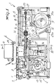
- the apparatus comprises a framework 2 which supports a first conveyor belt 3 for feeding containers which are to be closed, a heat-welding unit formed by a resting table 4 above which a welding head 6 is arranged and a second conveyor belt 5 for removing the closed containers.
- the first conveyor belt 3 is of the intermittent type to allow a certain number of containers to wait ahead of the heat-welding unit for the time required to transfer them onto the resting table.
- a continuous conveyor belt (not illustrated in figure 1) may be arranged ahead of said first conveyor belt 3; and its end portion 7 adjacent to the conveyor belt 3 has been schematically illustrated in figures 2 to 4.
- the resting table 4 is initially at the same level as the conveyor belts 3 and 5.
- the apparatus according to the invention advantageously comprises a pusher which is arranged laterally on said frame in a region adjacent to the table 4 and to the belts 3 and 5.
- said pusher comprises a first pusher element and a second pusher element, equal to one another or opposite with respect to the table and to the conveyor belts so as to engage the containers on opposite sides.
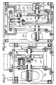
- the pusher 8 is formed by a grip region 9 having protrusions 10 adapted to engage with a plurality of containers C and connected by means of an intermediate portion 11 to a sleeve-like coupling portion 12.
- the grip portion 9 is conveniently substantially twice as long as the table.
- the shape of the protrusions 1 is extremely simple, since it adapts to lateral protrusions provided on the containers.
- a single lateral pusher element with more complicated grip elements, such as brackets may be provided so as to laterally and rearwardly engage the containers, which may possibly be supported on the opposite side with respect to the pusher by a longitudinal guide.
- a shaft 13 is used to actuate in practice the oscillatory and longitudinal translatory movements of the pusher 8; said shaft is mounted freely rotatable and slidable in a support 14 rigidly associated with the framework 2, in such a position that its axis is parallel to the direction of unwinding of the belts 3 and 5.
- the coupling portion 12 is fixed to one end of the shaft 13 and supports the intermediate portion 11 and the grip portion 9 so that the latter extends in a direction which is parallel to the shaft 13.
- An end sleeve 15 is fixed to the end of the shaft 13 which is opposite to the coupling portion 12; said sleeve supports a pusher bush 16 which is free to rotate but not to shift with respect to the sleeve 15.
- Said sleeve is internally provided with a longitudinal groove 17 which extends parallel to the axis of the shaft 13.
- Actuation means advantageously act on the pusher to make it oscillate about its axis of rotation from a first engagement position to a second disengagement position relatively to the plurality of containers.
- a torsion shaft 18 is supported coaxially to the actuation shaft 13 and has a longitudinal protrusion 19 engageable with the inner groove 17 of the end sleeve 15. Said shaft 18 is inserted in the sleeve 15 and extends within the shaft 13. In this manner, while the torsion shaft 18 transmits a rotation to the actuation shaft 13, the latter can slide freely along its axis by virtue of the groove provided inside the sleeve 15 as indicated in figure 5 by the arrows F1 and F2.
- a crank 20 is keyed to the free end of the torsion shaft 18 and is connected by means of a tension element 21 to an L-shaped lever 22 pivoted at 22a on the supporting framework 2.
- a roller 23 is pivoted on the other end of the L-shaped lever 22 and is slidably guided in a circular groove 24 provided on a cam defined beforehand in a wheel 25.
- Said wheel 25 and said cam path 24 constitute, as a whole, the first guiding means, and are actuated by a first motor reducer assembly 26.
- Second actuation means are advantageously provided and act on the pusher to move it longitudinally along its axis of rotation.
- the pivot 27 fixed to the bush 16 is connected by means of an articulating rod, not illustrated, to the end 28 of a first lever 29 of an articulated quadrilateral; said first lever is pivoted at 29a, and a second follower roller 31 is pivoted on the second lever 30 of said articulated quadrilateral; said second lever is pivoted at 30a.
- Said roller 31 is guided within a circular groove 32 defined on a cam provided beforehand in a second actuation wheel 33 which is rotatably mounted on the framework 2 and is actuated by a second motor reducer assembly 34.
- the table 4 is mounted on a slider 35 formed by columns 36 which can slide vertically in supports 37 rigidly associated with the supporting framework and are downwardly connected to a plate 38.
- Third actuation means conveniently act on the table 4 to move it vertically towards and/or away from the heat-welding head 6, as indicated by the arrow F3.
- Said third actuation means comprise a hydraulic or pneumatic piston which has the function of automatically adjusting the specific welding pressure, which can be preset for any kind and thickness of sealing lamina.
- the length of said piston 39 can be adjusted by means of screws and internal or female threads 40; said piston is connected to one end of an L-shaped lever 41 which is pivoted at 42 in the framework and has a follower roller 43 at the other end.
- Said roller is guided by a guiding groove 44 defined in a third actuation wheel 45 actuated by third motor means 46.
- the wheel 45 and the groove 44 constitute, as a whole, the third guiding means.
- Synchronization means are provided in order to mutually synchronize the movements of the three actuation means and are schematically indicated in figure 7 by the reference numeral 47; said means substantially consist of cam assemblies associated with electric switches for actuating motor reducer units which respectively actuate the actuation wheels 23, 33 and 45.
- rollers 48 and 49 are provided at the input and at the output of the heat-welding head and support a band of laminar material 50.
- the pusher 8 is shown in top view in a first terminal position in which the grip portions 9 are engaged with the containers, with their leading half arranged facing the table 4 and with their trailing half arranged facing the conveyor belt 3.
- Figure 4 illustrates the pushers just before they resume their cycle of transfer from their first longitudinal position, in which the grip portions are engaged with the containers, toward their second longitudinal terminal position.
- the operation of the device according to the invention is evident.
- the first and second actuation means are synchronized so as to provide movement from the first longitudinal position to the second one while the grip portions are engaged with the containers.
- the third actuation means are synchronized so as to keep the table 4 at the same level as the conveyor belts 3 and 5.
- the third actuation means are synchronized so as to cause the table 4 to move towards and subsequently away from the heat-welding head 6.
- the table is at the same level as the conveyor belts 3 and 5 and can thus start a new work cycle.
- the apparatus according to the invention fully achieves the aim of automating the process of heat-welding containers and of making it continuous with a high operating speed, while allowing to contain the dimensions of the apparatus in the direction parallel to the extension of the belts.
- the materials employed may be any according to the requirements and to the state of the art.
Landscapes
- Engineering & Computer Science (AREA)
- Mechanical Engineering (AREA)
- Package Closures (AREA)
- Lining Or Joining Of Plastics Or The Like (AREA)
- Closing Of Containers (AREA)
Claims (16)
- Automatische Vorrichtung zum Verschließen von der Vorrichtung durch einen Zufuhrförderer (7) zugeführten Behältern (c), mit
einem Gestell (2),
einer von diesem getragenen, einen oberhalb eines Auflagetisches (4) angeordneten Thermo-Schweißkopf (6) aufweisenden Verschließeinrichtung (4, 6),
einem zweiten, von einer Auslaufseite der Verschließeinrichtung (4, 6) wegführenden Förderband (5),
einem einen Griffabschnitt (9) bildenden Schieber (8) zum Erfassen mehrerer der Verschließeinrichtung (4, 6) zuzuführender und von ihr abzuführender Behälter (c),
einem ersten Antrieb (18 - 20, 22, 26) zur Betätigung des Schiebers (8), so daß dieser die mehreren Behälter (c) erfassen bzw. sie wieder freigeben kann,
mit einem Zweiten Antrieb (28 - 33) zur Längsverschiebung des Schiebers (8) entlang seiner Rotationsachse, und mit einem ersten, zwischen dem Zufuhrförderer (7) und der Verschließeinrichtung (4, 6) angeordneten Förderband (3), das vom Zufuhrförderer (7) zur Einlaufseite der Verschließeinrichtung (4, 6) führt, die Verschließeinrichtung (4, 6) ist von länglicher Form, um gleichzeitig zumindest einen Behälter zu verschließen;
gekennzeichnet durch folgende Merkmale:- das erste Förderband (3) ist von intermittierender Bauart und arbeitsmäßig mit der Verschließeinrichtung (4, 6) verbunden, um eine Anzahl von Behältern vor der Verschließeinrichtung (4, 6) für eine Zeitspanne warten zu lassen, die zu ihrem Vorschub auf den Auflagetisch (4) benötigt wird;- der Schieber (8) bewegt sich aus einer ersten Position, in der der Griffabschnitt (9) einen Leitabschnitt des ersten Bandförderers (3) sowie des Auf lagetisches (4) flankiert, in eine zweite Position, in der der Griffabschnitt (9) einen Ablaufabschnitt des zweiten Bandförderers (5) sowie des Auflagetisches (4) flankiert;- der Griffabschnitt (9) übergreift die Förderbänder (3) und (5) am Leit- bzw. Ablaufabschnitt mit einer Länge, die der Länge von zumindest einem zu bearbeitenden Behälter entspricht, wobei der zweite Bandförderer (5) arbeitsmäßig mit der Verschließeinrichtung (4, 6) verbunden ist. - Vorrichtung nach Anspruch 1, dadurch gekennzeichnet, daß sich der Greifer (9) angenähert parallel zur Vorschubrichtung der Behälter (C) erstreckt mit einer Nutzlänge, die angenähert doppelt so lang ist wie der Tisch (4), um so gleichzeitig jeweils die gleiche Anzahl von Behältern auf den Tisch zu bringen und von diesem wieder zu entfernen, wenn sich der Schieber (8) von der ersten Längsposition zu der zweiten Position bewegt.
- Vorrichtung nach Anspruch 1 oder 2, dadurch gekennzeichnet, daß der Greifer (9) mit seiner Vorderhälfte dem Tisch (4) zugewandt ist, wenn sich der Schieber (8) in der ersten Längsposition befindet, und daß der Greifer (9) mit seiner hinteren Hälfte dem Tisch zugewandt ist, wenn sich der Schieber (8) in der zweiten Längsposition befindet.
- Vorrichtung nach Anspruch 1, dadurch gekennzeichnet, daß der Tisch (4) auf dem Gestell (2) höhenverstellbar befestigt ist und mit Hilfe eines dritten Antriebs (39-46) vertikal von einer ersten, etwa in Höhe der Bänder (3,5) liegenden Höhe in eine zweite Ebene angehoben wird, in der er angenähert in der Ebene des Kopfes (6) liegt mit den dazwischenliegenden Behältern (C) und der Verschlußfolie (50).
- Vorrichtung nach einem oder mehreren der vorhergehenden Ansprüche, gekennzeichnet durch eine erste Einrichtung (47) zur jeweiligen Synchronisierung der Antriebe eins (18-20,22,26) und zwei (28-33), um den Schieber (8) während seiner Verschiebung aus der ersten in die zweite Position in seiner Greifstellung - bezogen auf die mehreren Behälter (C) zu halten, und um den Schieber (8) während seiner Rückbewegung aus der zweiten in die erste Position in seiner - bezogen auf die mehreren Behälter (C) - gelösten Stellung zu halten.
- Vorrichtung nach einem oder mehreren der vorhergehenden Ansprüche, gekennzeichnet durch eine zweite Einrichtung (47) zur jeweiligen Synchronisierung der Antriebe zwei (28-33) und drei (39-46), um den Tisch (4) auf der ersten Höhe zu halten, während der Schieber (8) sich von der ersten Position zu der zweiten Position bewegt, und um den Tisch (4) zum Schweißkopf (6) hin und wieder von ihm weg zu bewegen während der Rückbewegung des Schiebers (8) aus seiner zweiten Position in die erste Position.
- Vorrichtung nach einem oder mehreren der vorhergehenden Ansprüche, dadurch gekennzeichnet, daß der Schieber (8) ein Zwischenstück (11) aufweist zur Verbindung des Greifers (9) mit einem Kupplungsstück (12), das drehfest auf einem Ende einer Antriebswelle (13) befestigt ist, die drehbar und verschiebbar achsparallel zur Vorschubrichtung der Behälter (C) auf dem genannten Gestell (2) gelagert ist.
- Vorrichtung nach einem oder mehreren der vorhergehenden Ansprüche, dadurch gekennzeichnet, daß die Antriebswelle (13) innen hohl ist und an ihrem dem Kupplungsstück (12) entgegengesetzten Ende eine Endbuchse (15) aufweist, die innen mit einer Längsnut (17) versehen ist und eine Schiebehülse (16) trägt, die sich frei um die Buchse (15) drehen läßt und in Längsrichtung auf ihr arretiert ist.
- Vorrichtung nach einem oder mehreren der vorhergehenden Ansprüche, dadurch gekennzeichnet, daß der erste Antrieb (18-20,22,26) eine erste Führung (24,25) für eine erste Mitnehmerrolle (23) aufweist, die an einem Ende eines ersten Verbindungselements (22) drehgelagert ist, das zwischen der ersten Führung (24,25) und der Antriebswelle (13) angeordnet ist und einen Winkelhebel aufweist, der mittig am Gestell (2) angelenkt und mit einer Kurbel (20) verbunden ist, die mit einem Ende einer Torsionswelle (18) verkeilt ist, die an ihrem entgegengesetzten Ende eine Längsfeder (19) aufweist, die gleitend in die Innennut (17) der Endbuchse (15) eingreift.
- Vorrichtung nach einem oder mehreren der vorhergehenden Ansrpüche, dadurch gekennzeichnet, daß der zweite Antrieb (28-33) eine zweite Führung (32) für eine zweite Mitnehmerrolle (31) aufweist, die an einem Ende eines zweiten Verbindungselements (30) drehgelagert ist, das zwischen der zweiten Führung (32) und der Antriebswelle (13) angeordnet ist und ein Gelenkviereck aufweist, das am Gestell (2) angelenkt ist und durch eine zwischengesetzte Gelenkstange mit der Schieberhülse (16) verbunden ist.
- Vorrichtung nach einem oder mehreren der vorhergehenden Ansprüche, dadurchgekennzeichnet, daß der dritte Antrieb (39-46) eine dritte Führung (44,45) für eine dritte Mitnehmerrolle (43) aufweist, die an einem Ende eines dritten Verbindungselements (41) drehgelagert ist, das zwischen der dritten Führung (44,45) und einem Schlitten (35) angeordnet ist, der auf dem den Tisch (4) tragenden Gestell (2) vertikal verschiebbar ist, wobei das dritte Verbindungselement (41) durch einen Winkelhebel (41) gebildet ist, der am Gestell (2) angelenkt und mittels eines stangenförmigen Zwischenstücks mit dem Schlitten (35) verbunden ist.
- Vorrichtung nach einem oder mehreren der vorhergehenden Ansprüche, dadurch gekennzeichnet, daß das stangenförmige Element durch einen hydraulischen oder pneumatischen Kolben (39) gebildet ist, der den auf den Tisch (4) wirkenden Schweißdruck reguliert.
- Vorrichtung nach einem oder mehreren der vorhergehenden Ansprüche, dadurch gekennzeichnet, daß jede der drei Führungen eine Kreisbahn auf einem Exzenter (24,32,44) einer zugeordneten Antriebsscheibe (25,33,45) aufweist, die am Gestell (2) angebracht und von einem zugeordneten Motor (26,34,46) angetrieben ist, wobei die Kreisbahn gleitend mit jeweils der ersten, zweiten bzw. dritten Mitnehmerrolle gekuppelt ist.
- Vorrichtung nach einem oder mehreren der vorhergehenden Ansprüche, dadurch gekennzeichnet, daß der Schieber (8) ein erstes und ein zweites, identisch zueinander ausgebildetes Schieberelement aufweist, die einander bezogen auf den Tisch (4) und die Bänder (3,5) gegenüberliegen.
- Vorrichtung nach einem oder mehreren der vorhergehenden Ansprüche, dadurch gekennzeichnet, daß der Schieber (8) ein einziges seitliches Schieberelement aufweist, das mit Greifelementen zum seitlichen und rückwärtigen Erfassen der Behälter (C) versehen ist.
- Vorrichtung nach einem oder mehreren der vorhergehenden Ansprüche, dadurch gekennzeichnet, daß das erste Förderband (3) ein Taktförderband ist, das seine Förderbewegung unterbricht, wenn der Greifer (9) teilweise dem ersten Förderband (3) zugewandt ist.
Applications Claiming Priority (2)
| Application Number | Priority Date | Filing Date | Title |
|---|---|---|---|
| IT8819934A IT1216515B (it) | 1988-03-24 | 1988-03-24 | Apparecchiatura per la chiusura di contenitori con lamina di sigillatura. |
| IT1993488 | 1988-03-24 |
Publications (3)
| Publication Number | Publication Date |
|---|---|
| EP0334266A1 EP0334266A1 (de) | 1989-09-27 |
| EP0334266B1 EP0334266B1 (de) | 1992-09-30 |
| EP0334266B2 true EP0334266B2 (de) | 1995-10-25 |
Family
ID=11162465
Family Applications (1)
| Application Number | Title | Priority Date | Filing Date |
|---|---|---|---|
| EP89104968A Expired - Lifetime EP0334266B2 (de) | 1988-03-24 | 1989-03-20 | Vorrichtung zum Verschliessen von Behältern mittels einer versiegelbaren Folie |
Country Status (5)
| Country | Link |
|---|---|
| US (1) | US4974392A (de) |
| EP (1) | EP0334266B2 (de) |
| DE (1) | DE68903016T2 (de) |
| ES (1) | ES2034449T5 (de) |
| IT (1) | IT1216515B (de) |
Cited By (1)
| Publication number | Priority date | Publication date | Assignee | Title |
|---|---|---|---|---|
| EP2374717A1 (de) | 2010-04-09 | 2011-10-12 | G. MONDINI S.p.A. | Vorrichtung zum Siegeln von Schalen. |
Families Citing this family (34)
| Publication number | Priority date | Publication date | Assignee | Title |
|---|---|---|---|---|
| JP2568423Y2 (ja) * | 1992-03-06 | 1998-04-15 | 四国化工機株式会社 | 容器の密封装置 |
| IT227649Y1 (it) * | 1992-09-30 | 1997-12-15 | Comau Spa | Dispositivo per il cambio rapido di pallet porta-pezzo in una macchina di montaggio. |
| IT1269721B (it) * | 1994-05-06 | 1997-04-15 | Mondini G Spa | Macchina per la sigillatura di contenitori mediante l'applicazione di una lamina di copertura |
| US5522200A (en) * | 1995-02-10 | 1996-06-04 | Nestec Machine Systems Ltd. | Continuous motion sealer |
| GB2343536B (en) | 1998-11-06 | 2003-10-08 | Nokia Mobile Phones Ltd | Alerting apparatus |
| SE518494C2 (sv) * | 2001-02-09 | 2002-10-15 | Tetra Laval Holdings & Finance | Anordning och metod för att föra ut enskilda föremål från en rad av föremål |
| US7089718B2 (en) | 2002-06-10 | 2006-08-15 | Green-Line Products, Inc. | Apparatus for heat-shrinking film onto an open-topped container and method of using same |
| US20040020171A1 (en) * | 2002-06-10 | 2004-02-05 | Biba Scott I. | Web cutter |
| US6834476B2 (en) * | 2002-10-17 | 2004-12-28 | Ibaraki Seiki Machinery Company, Ltd. | Sealing and packaging device for cover film on tray |
| DE102004023474A1 (de) * | 2004-05-12 | 2005-12-15 | Multivac Sepp Haggenmüller Gmbh & Co. Kg | Verpackungsmaschine und Verfahren zum Verschließen von Behältern |
| US20050274092A1 (en) * | 2004-06-10 | 2005-12-15 | Packaging Technologies, Inc. | Continuous motion sealer |
| ITMI20072058A1 (it) | 2007-10-25 | 2009-04-26 | Mondini Spa G | Sistema per la sigillatura contemporanea di piu' file di contenitori |
| DE102008008678B4 (de) | 2008-02-12 | 2017-02-02 | Multivac Sepp Haggenmüller Se & Co. Kg | Verpackungsmaschine und Verfahren zum Verschließen von Behältern mit Folie |
| DE102008030510A1 (de) | 2008-06-27 | 2010-01-14 | Multivac Sepp Haggenmüller Gmbh & Co. Kg | Verpackungsmaschine mit einem Greifersystem |
| DE102008048831A1 (de) | 2008-09-25 | 2010-04-08 | Multivac Sepp Haggenmüller Gmbh & Co. Kg | Fördervorrichtung für eine Verpackungsmaschine |
| DE102009004837A1 (de) * | 2009-01-16 | 2010-07-22 | Multivac Sepp Haggenmüller Gmbh & Co. Kg | Mehrspurige Verpackungsmaschine |
| IT1396479B1 (it) * | 2009-08-10 | 2012-12-14 | Gruppo Fabbri S P A | Macchina per il confezionamento di prodotti in vassoi rigidi o semirigidi, chiusi superiormente a tenuta con un film termoplastico, particolarmente per produrre confezioni in atmosfera modificata. |
| DE102010027211B4 (de) * | 2010-07-15 | 2012-04-26 | Multivac Sepp Haggenmüller Gmbh & Co. Kg | Greifersystem für eine Schalenverschließmaschine |
| DE102010056316B4 (de) * | 2010-12-27 | 2015-07-02 | Multivac Sepp Haggenmüller Gmbh & Co. Kg | Schalenverschließmaschine und Verfahren zum Betrieb einer solchen Schalenverschließmaschine |
| ES2436274T3 (es) * | 2011-04-29 | 2013-12-30 | Multivac Sepp Haggenmüller Gmbh & Co. Kg | Máquina envasadora con equipo transportador |
| JP5940659B2 (ja) * | 2011-07-11 | 2016-06-29 | オーアンドアール・カートン・ルンド・アーベー | 厚紙製容器をシーリングするための機械および方法 |
| US20130097975A1 (en) | 2011-10-24 | 2013-04-25 | Remedi Technology Holdings, Llc | Packaging system for pharmaceutical dispenser and associated method |
| DE102012007598B4 (de) * | 2012-04-16 | 2022-02-24 | Multivac Sepp Haggenmüller Se & Co. Kg | Schiebereinheit und Verfahren zum Positionieren von Produkten auf einem Verpackungsträger |
| ITBO20120353A1 (it) * | 2012-06-26 | 2013-12-27 | Gruppo Fabbri Vignola Spa | Apparato per l'alimentazione ordinata di gruppi di vassoi ad una macchina adibita alla sigillatura dei vassoi stessi con l'applicazione di un film di copertura |
| DE102012015401B4 (de) * | 2012-08-03 | 2019-04-11 | Multivac Sepp Haggenmüller Se & Co. Kg | Schalenverschließmaschine |
| ES2524414T3 (es) * | 2012-09-10 | 2014-12-09 | Multivac Sepp Haggenmüller Gmbh & Co Kg | Máquina de cierre de cubetas |
| WO2014091503A1 (en) | 2012-12-10 | 2014-06-19 | G. Mondini Spa | Modified atmosphere packaging with perforation of the container |
| EP2945871A1 (de) | 2012-12-10 | 2015-11-25 | G. Mondini SpA | Siegelmaschine ohne restfolienabfall |
| DE102013021146A1 (de) * | 2013-12-12 | 2015-07-02 | Multivac Sepp Haggenmüller Gmbh & Co. Kg | Verpackungsmaschine und Verfahren mit losem Objektträger |
| TR201905641T4 (tr) * | 2015-03-09 | 2019-05-21 | Nexes Control Design Eng S L U | Ambalajlama hattı için çalışma istasyonu ve bu çalışma istasyonlarından en az iki adet içeren ambalajlama hattı. |
| ES2662934T3 (es) * | 2015-09-04 | 2018-04-10 | Multivac Sepp Haggenmüller Se & Co. Kg | Máquina de cierre de cubetas |
| IT201600076881A1 (it) | 2016-07-21 | 2018-01-21 | Mondini S R L | Macchina per la sigillatura di contenitori |
| DE102018213213B4 (de) * | 2018-08-07 | 2020-03-12 | Multivac Sepp Haggenmüller Se & Co. Kg | Verfahren zum Betrieb einer Schalenverschließmaschine |
| DE102019206345A1 (de) | 2019-05-03 | 2020-11-05 | Multivac Sepp Haggenmüller Se & Co. Kg | SCHALENVERSCHLIEßMASCHINE SOWIE VERFAHREN ZUM BETREIBEN EINER GREIFEREINRICHTUNG AN DER SCHALENVERSCHLIEßMASCHINE |
Family Cites Families (13)
| Publication number | Priority date | Publication date | Assignee | Title |
|---|---|---|---|---|
| US1577627A (en) * | 1924-10-23 | 1926-03-23 | Webster Thomas Herbert | Means for handling projectiles and other bodies |
| US2295049A (en) * | 1938-09-14 | 1942-09-08 | Tri State Cap & Cap Machinery | Machine for and method of applying covers to containers |
| US3135395A (en) * | 1960-03-21 | 1964-06-02 | Livernois Engineering Co | Transfer device |
| US3345797A (en) * | 1964-08-03 | 1967-10-10 | Dow Chemical Co | Heat sealing method and apparatus |
| US3453167A (en) * | 1966-05-13 | 1969-07-01 | Corley Miller Inc | Package handling mechanism |
| US3430782A (en) * | 1967-06-29 | 1969-03-04 | Edward J Henkel | Article transfer apparatus |
| US3507093A (en) * | 1967-08-16 | 1970-04-21 | Maryland Cup Corp | Container capping machine |
| AU4141068A (en) * | 1968-07-30 | 1970-02-05 | Empaques, Sociedad Anonima Industrial Y Commercial | Automatic machine for sealing containers |
| US3841468A (en) * | 1970-11-27 | 1974-10-15 | Owens Illinois Inc | Molded plastic container secondary operations machine |
| US3754667A (en) * | 1972-01-07 | 1973-08-28 | R Storch | Transfer mechanism |
| US3757961A (en) * | 1972-01-10 | 1973-09-11 | East Dayton Tool & Die Co | Article transfer apparatus |
| US4095390A (en) * | 1976-04-01 | 1978-06-20 | Mckenna Equipment Company, Inc. | Machine and process for capping and sealing containers |
| FR2601330B1 (fr) * | 1986-07-09 | 1989-07-28 | Robache Roger | Machine pour la fermeture d'une barquette, ou autre recipient de conditionnement, par soudure d'un film en matiere thermo-plastique sur les bords d'un tel recipient |
-
1988
- 1988-03-24 IT IT8819934A patent/IT1216515B/it active
-
1989
- 1989-03-20 DE DE68903016T patent/DE68903016T2/de not_active Ceased
- 1989-03-20 EP EP89104968A patent/EP0334266B2/de not_active Expired - Lifetime
- 1989-03-20 ES ES89104968T patent/ES2034449T5/es not_active Expired - Lifetime
- 1989-03-21 US US07/326,840 patent/US4974392A/en not_active Expired - Lifetime
Cited By (1)
| Publication number | Priority date | Publication date | Assignee | Title |
|---|---|---|---|---|
| EP2374717A1 (de) | 2010-04-09 | 2011-10-12 | G. MONDINI S.p.A. | Vorrichtung zum Siegeln von Schalen. |
Also Published As
| Publication number | Publication date |
|---|---|
| IT8819934A0 (it) | 1988-03-24 |
| IT1216515B (it) | 1990-03-08 |
| US4974392A (en) | 1990-12-04 |
| DE68903016T2 (de) | 1996-02-29 |
| DE68903016D1 (de) | 1992-11-05 |
| ES2034449T3 (es) | 1993-04-01 |
| EP0334266A1 (de) | 1989-09-27 |
| ES2034449T5 (es) | 1996-03-01 |
| EP0334266B1 (de) | 1992-09-30 |
Similar Documents
| Publication | Publication Date | Title |
|---|---|---|
| EP0334266B2 (de) | Vorrichtung zum Verschliessen von Behältern mittels einer versiegelbaren Folie | |
| US5475965A (en) | Machine for sealing containers by applying a covering film | |
| US4219988A (en) | Automatic high-speed wrapping machine | |
| US5443150A (en) | Apparatus for advancing preformed containers | |
| CN107848644B (zh) | 将单个或成组的产品包装在包装件中的包装机及其方法 | |
| EP1986916B1 (de) | Verfahren zur füllung von beuteln | |
| GB2139175A (en) | A machine for packing continuously moving articles with a strip of heat-shrinkable material | |
| CN112810912B (zh) | 一种底封热缩包膜包装机 | |
| US4209958A (en) | Article strapping | |
| US6942610B2 (en) | Web folding machine | |
| JP2012224442A (ja) | 横型製袋充填包装機の供給コンベヤ | |
| EP0465207B1 (de) | Verfahren und Vorrichtung zum Verpacken von elastisch verformbaren Gegenständen | |
| US5014496A (en) | Method of and apparatus for continuous bakery product wrapping | |
| US4207136A (en) | Welding machine for thermoplastic web | |
| CN212023147U (zh) | 一种自动化管材包装机 | |
| JP7319657B2 (ja) | ピロー包装機および通紙方法 | |
| EP3423360B1 (de) | Vorrichtung zum quer-verschieben von fortlaufenden artikeln | |
| EP2149448A2 (de) | Stapelumreifungsmaschine mit aus schweißbarem Kunststoff hergestellten Reifen | |
| EP1167201B1 (de) | Verfahren und Vorrichtung zum Umwickeln von Zigarren | |
| US5806392A (en) | Producing shaped articles | |
| US2107482A (en) | Wrapping or packing machine | |
| CN112607077B (zh) | 一种自动封盒机及封盒方法 | |
| US5107659A (en) | Method of and apparatus for continuous bakery product wrapping | |
| US5584789A (en) | Method and apparatus for forming non-round containers | |
| CN118387382A (zh) | 一种肉脯干包装机 |
Legal Events
| Date | Code | Title | Description |
|---|---|---|---|
| PUAI | Public reference made under article 153(3) epc to a published international application that has entered the european phase |
Free format text: ORIGINAL CODE: 0009012 |
|
| AK | Designated contracting states |
Kind code of ref document: A1 Designated state(s): CH DE ES FR GB IT LI NL |
|
| 17P | Request for examination filed |
Effective date: 19891025 |
|
| 17Q | First examination report despatched |
Effective date: 19910723 |
|
| GRAA | (expected) grant |
Free format text: ORIGINAL CODE: 0009210 |
|
| AK | Designated contracting states |
Kind code of ref document: B1 Designated state(s): CH DE ES FR GB IT LI NL |
|
| REF | Corresponds to: |
Ref document number: 68903016 Country of ref document: DE Date of ref document: 19921105 |
|
| ET | Fr: translation filed | ||
| ITF | It: translation for a ep patent filed | ||
| PLBI | Opposition filed |
Free format text: ORIGINAL CODE: 0009260 |
|
| 26 | Opposition filed |
Opponent name: ALCAN ALUMINIUMWERKE GMBH Effective date: 19930630 |
|
| NLR1 | Nl: opposition has been filed with the epo |
Opponent name: ALCAN ALUMINIUMWERKE GMBH. |
|
| PUAH | Patent maintained in amended form |
Free format text: ORIGINAL CODE: 0009272 |
|
| STAA | Information on the status of an ep patent application or granted ep patent |
Free format text: STATUS: PATENT MAINTAINED AS AMENDED |
|
| 27A | Patent maintained in amended form |
Effective date: 19951025 |
|
| AK | Designated contracting states |
Kind code of ref document: B2 Designated state(s): CH DE ES FR GB IT LI NL |
|
| ITF | It: translation for a ep patent filed | ||
| REG | Reference to a national code |
Ref country code: CH Ref legal event code: AEN Free format text: MAINTIEN DU BREVET DONT L'ETENDUE A ETE MODIFIEE |
|
| NLR2 | Nl: decision of opposition | ||
| ET3 | Fr: translation filed ** decision concerning opposition | ||
| REG | Reference to a national code |
Ref country code: ES Ref legal event code: DC2A Kind code of ref document: T5 Effective date: 19960301 |
|
| NLR3 | Nl: receipt of modified translations in the netherlands language after an opposition procedure | ||
| K2C3 | Correction of patent specification (complete document) published |
Effective date: 19920930 |
|
| REG | Reference to a national code |
Ref country code: CH Ref legal event code: NV Representative=s name: MARK-PAT MODIANO S.A. |
|
| REG | Reference to a national code |
Ref country code: GB Ref legal event code: IF02 |
|
| REG | Reference to a national code |
Ref country code: CH Ref legal event code: PCAR Free format text: G. MONDINI S.P.A.#VIA BRESCIA, 5-7#COLOGNE BRESCIANO (BRESCIA) (IT) -TRANSFER %%- G. MONDINI S.P.A.#VIA BRESCIA, 5-7#COLOGNE BRESCIANO (BRESCIA) (IT) Representative=s name: MARK-PAT MODIANO S.A, CH |
|
| PGFP | Annual fee paid to national office [announced via postgrant information from national office to epo] |
Ref country code: ES Payment date: 20080311 Year of fee payment: 20 Ref country code: CH Payment date: 20080314 Year of fee payment: 20 |
|
| PGFP | Annual fee paid to national office [announced via postgrant information from national office to epo] |
Ref country code: NL Payment date: 20080328 Year of fee payment: 20 Ref country code: GB Payment date: 20080326 Year of fee payment: 20 Ref country code: IT Payment date: 20080317 Year of fee payment: 20 |
|
| PGFP | Annual fee paid to national office [announced via postgrant information from national office to epo] |
Ref country code: FR Payment date: 20080313 Year of fee payment: 20 Ref country code: DE Payment date: 20080327 Year of fee payment: 20 |
|
| REG | Reference to a national code |
Ref country code: CH Ref legal event code: PL |
|
| REG | Reference to a national code |
Ref country code: GB Ref legal event code: PE20 Expiry date: 20090319 |
|
| REG | Reference to a national code |
Ref country code: ES Ref legal event code: FD2A Effective date: 20090321 |
|
| PG25 | Lapsed in a contracting state [announced via postgrant information from national office to epo] |
Ref country code: NL Free format text: LAPSE BECAUSE OF EXPIRATION OF PROTECTION Effective date: 20090320 |
|
| NLV7 | Nl: ceased due to reaching the maximum lifetime of a patent |
Effective date: 20090320 |
|
| PG25 | Lapsed in a contracting state [announced via postgrant information from national office to epo] |
Ref country code: GB Free format text: LAPSE BECAUSE OF EXPIRATION OF PROTECTION Effective date: 20090319 |
|
| PG25 | Lapsed in a contracting state [announced via postgrant information from national office to epo] |
Ref country code: ES Free format text: LAPSE BECAUSE OF EXPIRATION OF PROTECTION Effective date: 20090321 |
|
| PG25 | Lapsed in a contracting state [announced via postgrant information from national office to epo] |
Ref country code: DE Free format text: THE PATENT HAS BEEN ANNULLED BY A DECISION OF A NATIONAL AUTHORITY Effective date: 20091007 |