EP0334382B1 - Appareil magnétique pour système d'image de résonance magnétique - Google Patents
Appareil magnétique pour système d'image de résonance magnétique Download PDFInfo
- Publication number
- EP0334382B1 EP0334382B1 EP89105306A EP89105306A EP0334382B1 EP 0334382 B1 EP0334382 B1 EP 0334382B1 EP 89105306 A EP89105306 A EP 89105306A EP 89105306 A EP89105306 A EP 89105306A EP 0334382 B1 EP0334382 B1 EP 0334382B1
- Authority
- EP
- European Patent Office
- Prior art keywords
- bore
- helium
- magnet apparatus
- thermal radiation
- radiation shield
- Prior art date
- Legal status (The legal status is an assumption and is not a legal conclusion. Google has not performed a legal analysis and makes no representation as to the accuracy of the status listed.)
- Expired - Lifetime
Links
- 238000002595 magnetic resonance imaging Methods 0.000 title claims description 13
- 239000001307 helium Substances 0.000 claims description 38
- 229910052734 helium Inorganic materials 0.000 claims description 38
- 230000005291 magnetic effect Effects 0.000 claims description 37
- SWQJXJOGLNCZEY-UHFFFAOYSA-N helium atom Chemical compound [He] SWQJXJOGLNCZEY-UHFFFAOYSA-N 0.000 claims description 36
- 230000005855 radiation Effects 0.000 claims description 23
- 238000005057 refrigeration Methods 0.000 claims description 9
- 238000001816 cooling Methods 0.000 claims description 8
- 230000004907 flux Effects 0.000 claims description 8
- 239000007788 liquid Substances 0.000 claims description 8
- 239000011810 insulating material Substances 0.000 claims description 3
- 239000000463 material Substances 0.000 claims description 2
- 239000003302 ferromagnetic material Substances 0.000 claims 1
- 230000000149 penetrating effect Effects 0.000 claims 1
- 238000003745 diagnosis Methods 0.000 description 10
- 230000003068 static effect Effects 0.000 description 8
- 230000000694 effects Effects 0.000 description 5
- IJGRMHOSHXDMSA-UHFFFAOYSA-N Atomic nitrogen Chemical compound N#N IJGRMHOSHXDMSA-UHFFFAOYSA-N 0.000 description 4
- 230000003247 decreasing effect Effects 0.000 description 4
- 206010040007 Sense of oppression Diseases 0.000 description 3
- 230000005284 excitation Effects 0.000 description 3
- 238000009413 insulation Methods 0.000 description 3
- 238000004519 manufacturing process Methods 0.000 description 3
- 239000003507 refrigerant Substances 0.000 description 3
- 230000035807 sensation Effects 0.000 description 3
- 238000003384 imaging method Methods 0.000 description 2
- 238000000034 method Methods 0.000 description 2
- 229910052757 nitrogen Inorganic materials 0.000 description 2
- 206010009244 Claustrophobia Diseases 0.000 description 1
- 238000010586 diagram Methods 0.000 description 1
- 239000007789 gas Substances 0.000 description 1
- 150000002371 helium Chemical class 0.000 description 1
- 239000011796 hollow space material Substances 0.000 description 1
- 238000009434 installation Methods 0.000 description 1
- 238000001208 nuclear magnetic resonance pulse sequence Methods 0.000 description 1
- 239000012466 permeate Substances 0.000 description 1
- 208000019899 phobic disease Diseases 0.000 description 1
- 238000010791 quenching Methods 0.000 description 1
- 230000000171 quenching effect Effects 0.000 description 1
Images
Classifications
-
- G—PHYSICS
- G01—MEASURING; TESTING
- G01R—MEASURING ELECTRIC VARIABLES; MEASURING MAGNETIC VARIABLES
- G01R33/00—Arrangements or instruments for measuring magnetic variables
- G01R33/20—Arrangements or instruments for measuring magnetic variables involving magnetic resonance
- G01R33/28—Details of apparatus provided for in groups G01R33/44 - G01R33/64
- G01R33/38—Systems for generation, homogenisation or stabilisation of the main or gradient magnetic field
- G01R33/381—Systems for generation, homogenisation or stabilisation of the main or gradient magnetic field using electromagnets
- G01R33/3815—Systems for generation, homogenisation or stabilisation of the main or gradient magnetic field using electromagnets with superconducting coils, e.g. power supply therefor
-
- F—MECHANICAL ENGINEERING; LIGHTING; HEATING; WEAPONS; BLASTING
- F17—STORING OR DISTRIBUTING GASES OR LIQUIDS
- F17C—VESSELS FOR CONTAINING OR STORING COMPRESSED, LIQUEFIED OR SOLIDIFIED GASES; FIXED-CAPACITY GAS-HOLDERS; FILLING VESSELS WITH, OR DISCHARGING FROM VESSELS, COMPRESSED, LIQUEFIED, OR SOLIDIFIED GASES
- F17C3/00—Vessels not under pressure
- F17C3/02—Vessels not under pressure with provision for thermal insulation
- F17C3/08—Vessels not under pressure with provision for thermal insulation by vacuum spaces, e.g. Dewar flask
- F17C3/085—Cryostats
-
- G—PHYSICS
- G01—MEASURING; TESTING
- G01R—MEASURING ELECTRIC VARIABLES; MEASURING MAGNETIC VARIABLES
- G01R33/00—Arrangements or instruments for measuring magnetic variables
- G01R33/20—Arrangements or instruments for measuring magnetic variables involving magnetic resonance
- G01R33/28—Details of apparatus provided for in groups G01R33/44 - G01R33/64
- G01R33/42—Screening
- G01R33/421—Screening of main or gradient magnetic field
-
- H—ELECTRICITY
- H01—ELECTRIC ELEMENTS
- H01F—MAGNETS; INDUCTANCES; TRANSFORMERS; SELECTION OF MATERIALS FOR THEIR MAGNETIC PROPERTIES
- H01F6/00—Superconducting magnets; Superconducting coils
-
- G—PHYSICS
- G01—MEASURING; TESTING
- G01R—MEASURING ELECTRIC VARIABLES; MEASURING MAGNETIC VARIABLES
- G01R33/00—Arrangements or instruments for measuring magnetic variables
- G01R33/20—Arrangements or instruments for measuring magnetic variables involving magnetic resonance
- G01R33/28—Details of apparatus provided for in groups G01R33/44 - G01R33/64
- G01R33/38—Systems for generation, homogenisation or stabilisation of the main or gradient magnetic field
- G01R33/3806—Open magnet assemblies for improved access to the sample, e.g. C-type or U-type magnets
Definitions
- This invention relates to a magnet apparatus for use in a magnetic resonance imaging system (MRI system) and more specifically to a magnet apparatus having a cryostat to keep a superconducting coil, which produces a static magnetic field, in the superconducting state.
- MRI system magnetic resonance imaging system
- the MRI system has formed therein a bore to accommodate a patient.
- a working volume where the patient's part subject to diagnosis is placed is defined in the bore.
- a magnet apparatus is disposed surrounding the bore and comprises a superconducting coil to produce a static magnetic field in the working volume and a cryostat to hold the superconducting coil in the superconducting state.
- a gradient magnetic field is superposed on the static magnetic field and high frequency signals are applied to the patient's part subject to diagnosis. Magnetic resonance signals from that part of the patient are detected and used to form a tomographic image of the part for diagnosis.
- the static magnetic field formed in the working volume is required to be high homogeneity.
- the production costs of superconducting coils and cryostats have been pushed up substantially.
- superconducting coils and cryostats are great in size and weight it is difficult to transport MRI systems and install these systems in the existing hospitals or the like.
- the whole body of the patient is accomodated in the long and narrow bore. Therefore, the patient has an oppressive sensation and often suffers from claustrophobia.
- MRI diagnosis is in progress, the doctor cannot directly observe the patient. If, under such a situation, the patient's condition takes a sudden turn for the worse, the doctor is unable to take an emergency measure.
- Prior art document EP-A-0 116 364 discloses a magnet apparatus for use in NMR imaging systems.
- This magnet apparatus comprises a superconducting coil disposed radially outside a bore a cryostat which accomodates the superconducting coil, a helium chamber, keeping the superconducting coil in the superconducting state, a vacuum container, enclosing the helium chamber, a thermal radiation shield, disposed in the internal space of the vacuum chamber and surrounding the helium chamber and, cooling means for cooling the thermal radiation heat from entering the helium chamber from outside.
- prior art document GB-A-2 149 901 describes a low temperature container describes a container which comprises a heat shield and a refrigerating heat exchanger contacting the shield.
- the shield covers a container for a cryogen such as liquid helium.
- the heat exchanger is connected to a working gas feed pipe and a return pipe to and from a low temperature generating heat exchanger, a preliminary heat exchanger and a compressor of a refrigerator.
- the heat exchanger are in a vacuum container, the pipes in a vacuum pipe and the cryogen container in a vacuum casing.
- the cryogen container houses a superconductive electromagnet for an NMR computed tomograph.
- prior art document EP-A-0 122 498 describes a cryostat including a horizontal hollow space section of room temperature in which a liquid helium vessel is supported by a plurality of support structures each having a multiple cylinder of small thickness and a liquid nitrogen vessel is supported by a plurality of tension rods.
- prior art document PATENT ABSTRACTS OF JAPAN vol. 10, no. 340 (E-455)(2396), 18th. November 1986, (JP-A-61 144 802) discloses a superconductive electromagnet device in which two sets of superconductive coils whereon a superconductive wire is wound around, are arranged and housed in a liquid-helium-filled ocntainer in such a manner that the condition of uniform magnetic field is satisfied.
- the container is enveloped by a radiant shield, and it is placed in a vacuum container through the intermediary of a heat-insulating vacuum layer. Subsequently, a current supply part corresponding to coils is inserted into the container while the container is being airtightly sealed.
- the coils are connected to an exciting power source, and the values of current to be applied to the coils are made independent and allow them to make a change. Through these procedures, a highly precise uniform magnetic field is obtained, and when a quenching is generated by some cause, the current on the coil couple is cut-off, and the quantity of emitted energy is reduced.
- a permanent current switch may be provided on the coil in this case.
- the present invention provides a magnet apparatus as specified in claim 1.
- the volume of the cryostat has been made smaller than before without reducing the heat-insulation effects of the helium chamber.
- the volume of the cryostat is 50% of that of conventional cryostats.
- the bore can be designed to comply with the condition that 1.0 ⁇ L/B ⁇ 1.9 where L is the length of the bore in parallel with the Z axis and B is the diameter of the bore. The reason why the range of the value of L/B has been determined will be mentioned in the following description of the preferred embodiment.
- the length L parallel with the Z axis of the bore has been defined to be relatively short while the dimensions of the working volume necessary for diagnosis are secured inside the bore. Consequently, the oppressive sensation of the patient in the bore is lessened.
- cryostat has been reduced in size and weight. Therefore, MRI systems can be easily transported and installed in the existing hospitals or the like. In addition, the production cost of the cryostat can be decreased.
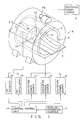
- RF coil 3 is disposed surrounding the part subject to diagnosis of patient 1.
- RF coil 3 is connected to RF oscillator 15 and RF receiver 16.
- RF oscillator/receiver 15, 16 and excitation power sources 11, 12 and 13 are connected to central control unit 14.
- This control unit 14 is connected to display/operation console 17.
- the magnet apparatus 6 When excited, the magnet apparatus 6 produces a uniform magnetostatic field in the working volume. Under this condition, the X, Y and Z gradient magnetic fields produced by X, Y and Z gradient magnetic coils 5 are superposed on the static magnetic field.
- RF oscillator 15 is driven according to a pulse sequence, pulse signals are sent to RF coil 3.
- magnetic resonance signals are induced in the patient's part under diagnosis.
- These magnetic resonance signals are detected by RF coil 3 and sent through RF receiver 16 to central control unit 14, which performs the image reproduction process and provides image information. This image information is converted into video signals which are used to display a tomographic image on display console 17.
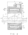
- Magnet apparatus 6 comprises superconducting coil 31 for producing a static or a main magnetic field in working volume 18 and cryostat 32 to keep magnet coil 31 in the superconducting state.
- Cryostat 32 includes helium chamber 41 containing liquid helium at a temperature of 4.2K. In this helium chamber 41, superconducting coil 31 is immersed with liquid helium and kept in superconducting state. Helium chamber 41 is covered by single thermal radiation shield 42. Cryostat 32 also further includes vacuum container 43 having an internal space held in a vacuum. Both helium chamber 41 and thermal radiation shield 42 are accommodated in the internal space. Multiple layer heat insulating material 44 is arranged also in the internal space. Vacuum container 43 comprises a cylindrical wall which defines bore 7.
- Cryostat 32 comprises means for cooling thermal radiation shield 42.
- the cooling means is constituted of a refrigerator having a single refrigeration stage.
- the cooling means comprises refrigerator 45 provided at the top of vacuum container 43, cylinder 46 having one end connected to refrigerator 45 and another end, and single refrigeration stage 48 connected to another end of cylinder 46 and connected through heat transfer plate 47 to thermal radiation shield 42.
- the refrigerant cooled by refrigerator 45 is adiabatically expanded in cylinder 46.
- refrigeration stage 48 is cooled to the temperature of 30K.
- Refrigeration stage 48 takes the heat through heat transfer plate 47 from radiation shield 42. Consequently, radiation shield 42 is cooled to 30K and kept at this temperature.
- helium chamber 41 is insulated from the radiant heat and the temperature in helium chamber 41 is kept at 4.2K.
- the conventional cryostat comprises an inner thermal radiation shield enclosing a helium chamber and connected to a refrigeration stage of 20K and an outer thermal radiation shield enclosing the inner shield and connected to a refrigeration stage of 80K.
- the inner and outer shields are cooled continuously at 20K and 80K, respectively, and cooperate with the internal space of the vacuum chamber to cut off the radiant heat.
- the cryostat having two shields, is relatively large in volume. This results in the relatively long bore and the relatively great sense of oppression that the patient has.
- cryostat 32 includes single thermal radiation shield 42. Therefore, cryostat 32 can be designed to have a small volume.
- the surface area of the cryostat can be made smaller than before, accordingly.
- the amount of radiant heat that may enter the helium chamber through the surface of the cryostat can be made smaller than in conventional cryostats. Therefore, the cryostat, though with only one thermal radiation shield, exerts sufficient heat insulation effects to insulate the helium chamber from the heat.
- the cryostat can be decreased in volume without reducing the heat insulation effects of the helium chamber.
- the volume of the cryostat of this invention is half that of the conventional cryostat.
- the thermal radiation shield 42 is cooled by refrigerator 45 with a single refrigeration stage.
- the refrigerant such as liquid nitrogen which is conventionally used to cool the thermal radiation shield is not required.
- the container to store the refrigerant can be done away with and therefore the volume of the cryostat can be further decreased.
- the cryostat has a reduced volume. Therefore, the bore dimensions may be determined to conform to the condition that 1.0 ⁇ L/B ⁇ 1.9 where L is the length along the Z axis of bore 7 and B is its diameter.
- the L/B is determined for the reasons described below. It is considered that the required diameter of the working volume for diagnosis is 100 cm. Therefore, the L needs to be more than or equal to 100 cm. The B may be about 100 cm. Meanwhile, in order to lessen the sense of oppression that the patient has in bore 7, the L needs to be less than 190 cm. From the foregoing, we have: 100 cm ⁇ L ⁇ 190 cm. Therefore, (100 cm/100 cm) ⁇ L/B ⁇ (190 cm/100 cm).
- the length L along the Z axis of the bore is designed to be relatively short while the working volume necessary for diagnosis is secured in the bore. As a result, the patient's oppressive sensation is lessened.
- cryostat is reduced both in volume and weight. This makes it easy to transport MRI systems and install them in the existing hospitals or the like. The production cost of cryostats is also decreased.
- the bore can be designed to have dimensions that comply with 1.0 ⁇ L/B ⁇ 1.9.
- the length L along the Z axis of the bore is determined to be relatively short. In consequence, the patient's trepidation in bore 7 is eased.
- the magnet apparatus further comprises a film sheet 65 serving as a magnetic shield and consisting of a superconducting material (e.g. NbTi).
- This film sheet 65 is bonded to the external circumferential surface of the cylindrical part of helium chamber 41 and the outer faces of the disc-like end parts thereof.
- Film sheet 65 may be bonded to the internal cylindrical surface of helium chamber 41. That is, film sheet 65 has only to be cooled by helium chamber 41 and kept in the superconducting state.
- film sheet 65 When the leakage flux of the static magnetic field permeates film sheet 65, film sheet 65 produces a magnetic flux to offset the leakage flux by the Meissner effect. Thus, the magnetic fringe field is reduced.
- film sheet 65 is extremely light compared with a yoke magnetic shield. This facilitates the transportation and installation of the MRI system.
- film sheet 65 is positioned closer than the yoke magnetic shield to superconducting magnet coil 31. For this reason, film sheet 65 can isolate the magnetic fringe field more efficiently than the yoke magnetic field.
Landscapes
- Physics & Mathematics (AREA)
- Engineering & Computer Science (AREA)
- Condensed Matter Physics & Semiconductors (AREA)
- General Physics & Mathematics (AREA)
- Health & Medical Sciences (AREA)
- Epidemiology (AREA)
- Electromagnetism (AREA)
- Power Engineering (AREA)
- Thermal Sciences (AREA)
- Mechanical Engineering (AREA)
- General Engineering & Computer Science (AREA)
- Magnetic Resonance Imaging Apparatus (AREA)
Claims (5)
- Un appareil magnétique à utiliser dans des systèmes d'image de résonance magnétique, ledit appareil magnétique comportant un axe et un alésage (7) s'étendant coaxialement à l'axe (7) et agencé pour recevoir un corps examiné (1), ledit alésage (7) présentant la longueur L parallèle à l'axe et le diamètre B, ledit appareil magnétique comportant :
un enroulement supraconducteur (31) disposé coaxialement à l'axe et radialement à l'extérieur de l'alésage (7) et capable de produire un champ magnétique principal à l'intérieur de l'alésage (7) ; et
un cryostat (32) présentant une paroi cylindrique qui définit l'alésage (7), recevant ledit enroulement supraconducteur (31) et maintenant ledit enroulement (31) dans l'état supraconducteur, ledit cryostat comportant :
une chambre d'hélium (41) contenant de l'hélium liquide, ladite chambre d'hélium (41) recevant ledit enroulement supraconducteur (31) immergé dans l'hélium liquide, pour maintenir ainsi ledit enroulement supraconducteur (31) dans l'état supraconducteur ;
un récipient à vide (43) présentant un espace intérieur sous vide dans lequel ladite chambre d'hélium (41) est reçue ;
un écran (42) de radiation thermique disposé dans l'espace intérieur dudit récipient à vide (43) et entourant ladite chambre d'hélium (41); et
des moyens pour refroidir ledit écran de radiation thermique à une température spécifiée, de manière que ledit écran (42) de radiation thermique coopère avec l'espace intérieur dudit récipient à vide (43) pour empêcher la plus grande partie de la chaleur radiante de pénétrer dans ladite chambre d'hélium (41) à partir de l'extérieur dudit récipient à vide (43), ladite chambre d'hélium (41) étant ainsi isolée de la chaleur radiante, ledit appareil magnétique étant caractérisé en ce que :- les dimensions de l'alésage (7) satisfont aux relations 1,0 ≦ L/B < 1,9 entre la longueur L et le diamètre B de l'alésage (7),- un écran magnétique est prévu pour isoler le flux du champ magnétique principal fuyant depuis l'intérieur de l'alésage (7) vers l'extérieur de celui-ci, et- ledit écran magnétique comporte un écran magnétique en pellicule (65) formé d'une matière supraconductrice qui est étroitement adaptée à ladite chambre d'hélium (41) et produit un flux magnétique pour décaler le flux de fuite du flux magnétique principal pénétrant à l'intérieur de l'écran magnétique en pellicule (65). - Un appareil magnétique selon la revendication 1, caractérisé en ce que lesdits moyens de refroidissement comportent un réfrigérateur (45) présentant un étage de réfrigération (48) relié audit écran de radiation thermique, de sorte que l'étage de réfrigération prend la chaleur dudit écran de radiation thermique (42) et refroidit ledit écran de radiation (42).
- Un appareil magnétique selon la revendication 1, caractérisé en ce que lesdits moyens de refroidissement comportent un tube (61) étroitement adapté audit écran de radiation thermique (42), ledit tube (61) présentant une extrémité (62) débouchant dans ladite chambre d'hélium (41) et l'extrémité opposée (63) débouchant à l'extérieur dudit récipient à vide (43), de sorte que l'hélium évaporé dans ladite chambre d'hélium (41) traverse ledit tube (61) et est évacué à l'extérieur dudit récipient à vide (43) et, lorsqu'il est évacué, l'hélium évaporé refroidit ledit écran de radiation thermique (42).
- Un appareil magnétique selon la revendication 1, caractérisé en ce que ledit récipient vide (43) présente une matière thermiquement isolante (44) placée dans son espaçe intérieur.
- Un appareil magnétique selon la revendication 1, caractérisé en ce que ledit écran magnétique comporte un écran magnétique en bague (55) qui est constitué en une matière ferromagnétique et est prévu à l'extérieur du cryostat (32) pour absorber le flux de fuite du champ magnétique principal.
Applications Claiming Priority (2)
| Application Number | Priority Date | Filing Date | Title |
|---|---|---|---|
| JP69620/88 | 1988-03-25 | ||
| JP63069620A JPH01243503A (ja) | 1988-03-25 | 1988-03-25 | 磁気共鳴イメージング装置用静磁界磁石 |
Publications (2)
| Publication Number | Publication Date |
|---|---|
| EP0334382A1 EP0334382A1 (fr) | 1989-09-27 |
| EP0334382B1 true EP0334382B1 (fr) | 1993-07-21 |
Family
ID=13408099
Family Applications (1)
| Application Number | Title | Priority Date | Filing Date |
|---|---|---|---|
| EP89105306A Expired - Lifetime EP0334382B1 (fr) | 1988-03-25 | 1989-03-23 | Appareil magnétique pour système d'image de résonance magnétique |
Country Status (4)
| Country | Link |
|---|---|
| US (1) | US4924185A (fr) |
| EP (1) | EP0334382B1 (fr) |
| JP (1) | JPH01243503A (fr) |
| DE (1) | DE68907621T2 (fr) |
Families Citing this family (21)
| Publication number | Priority date | Publication date | Assignee | Title |
|---|---|---|---|---|
| JPH03139328A (ja) * | 1989-10-25 | 1991-06-13 | Toshiba Corp | Mri装置用超電導マグネット |
| US5136273A (en) * | 1988-10-17 | 1992-08-04 | Kabushiki Kaisha Toshiba | Magnet apparatus for use in a magnetic resonance imaging system |
| JPH03182232A (ja) * | 1989-12-11 | 1991-08-08 | Toshiba Corp | 磁気共鳴イメージング装置 |
| NL9001300A (nl) * | 1990-06-08 | 1992-01-02 | Koninkl Philips Electronics Nv | Magneetstelsel voor magnetische resonantie. |
| JPH0464338A (ja) * | 1990-07-03 | 1992-02-28 | Toshiba Corp | 磁気共鳴イメージング装置用磁石 |
| NL9002621A (nl) * | 1990-11-30 | 1992-06-16 | Koninkl Philips Electronics Nv | Magnetisch resonantie apparaat met afschermende magneet. |
| US5282229A (en) * | 1991-02-15 | 1994-01-25 | Kabushiki Kaisha Toshiba | Method and apparatus for measuring gap between adjoining fuel rods of fuel assembly |
| JP2996545B2 (ja) | 1991-08-30 | 2000-01-11 | キヤノン株式会社 | モータ制御方法及び装置 |
| US5278502A (en) * | 1991-09-13 | 1994-01-11 | General Electric Company | Refrigerated superconducting MR magnet with integrated cryogenic gradient coils |
| US5258710A (en) * | 1992-03-27 | 1993-11-02 | General Electric Company | Cryogenic probe for NMR microscopy |
| US5359310A (en) * | 1992-04-15 | 1994-10-25 | Houston Advanced Research Center | Ultrashort cylindrical shielded electromagnet for magnetic resonance imaging |
| US5382904A (en) * | 1992-04-15 | 1995-01-17 | Houston Advanced Research Center | Structured coil electromagnets for magnetic resonance imaging and method for fabricating the same |
| US6323632B1 (en) * | 1999-08-13 | 2001-11-27 | Coulter International Corp. | Solid state RF oscillator-detector for flow cytometer |
| US20060226940A1 (en) * | 2005-04-07 | 2006-10-12 | Hitachi Global Storage Technologies | Method and apparatus for setting a sensor AFM with a superconducting magnet |
| US7378848B2 (en) * | 2006-05-05 | 2008-05-27 | M2M Imaging Corp. | Magnetic resonance coil system |
| JP4422711B2 (ja) * | 2006-11-20 | 2010-02-24 | 株式会社日立製作所 | 超電導磁石装置および磁気共鳴撮像装置 |
| JP5627067B2 (ja) * | 2008-12-01 | 2014-11-19 | オリンパス株式会社 | 生体観察システム及びこの生体観察システムの駆動方法 |
| GB2507792B (en) * | 2012-11-12 | 2015-07-01 | Siemens Plc | Combined MRI and radiation therapy system |
| JP2017011236A (ja) * | 2015-06-26 | 2017-01-12 | 株式会社神戸製鋼所 | 多層磁気シールド |
| WO2022044122A1 (fr) * | 2020-08-25 | 2022-03-03 | キヤノンメディカルシステムズ株式会社 | Procédé et dispositif d'uniformisation d'un champ magnétique statique généré à partir d'un aimant supraconducteur |
| CN118043694A (zh) * | 2021-12-10 | 2024-05-14 | 上海联影医疗科技股份有限公司 | 成像和治疗的系统和方法 |
Family Cites Families (11)
| Publication number | Priority date | Publication date | Assignee | Title |
|---|---|---|---|---|
| DE3123493A1 (de) * | 1981-06-13 | 1982-12-30 | Bruker Analytische Meßtechnik GmbH, 7512 Rheinstetten | Elektromagnet fuer die nmr-tomographie |
| DE3460231D1 (en) * | 1983-02-09 | 1986-07-24 | Bruker Analytische Messtechnik | Cooling device for a low temperature magnetic system |
| JPS59172576A (ja) * | 1983-03-23 | 1984-09-29 | Kao Corp | ホツトメルト接着剤 |
| DE3471998D1 (en) * | 1983-04-15 | 1988-07-14 | Hitachi Ltd | Cryostat |
| JPS60104899A (ja) * | 1983-11-09 | 1985-06-10 | Aisin Seiki Co Ltd | 冷凍機と連結した低温容器 |
| GB8410972D0 (en) * | 1984-04-30 | 1984-06-06 | Oxford Magnet Tech | Magnet assembly |
| JPS61144802A (ja) * | 1984-12-19 | 1986-07-02 | Toshiba Corp | 超電導電磁石装置 |
| JPS62279607A (ja) * | 1986-05-28 | 1987-12-04 | Fuji Electric Co Ltd | 均一磁場マグネツトの磁気シ−ルド |
| US4733189A (en) * | 1986-06-03 | 1988-03-22 | Massachusetts Institute Of Technology | Magnetic resonance imaging systems |
| JPS63272335A (ja) * | 1986-11-18 | 1988-11-09 | Toshiba Corp | 磁気共鳴イメ−ジング装置 |
| US4837541A (en) * | 1987-04-02 | 1989-06-06 | General Electric Company | Shield suspension system for a magnetic resonance cryostat |
-
1988
- 1988-03-25 JP JP63069620A patent/JPH01243503A/ja active Pending
-
1989
- 1989-03-23 DE DE89105306T patent/DE68907621T2/de not_active Expired - Lifetime
- 1989-03-23 EP EP89105306A patent/EP0334382B1/fr not_active Expired - Lifetime
- 1989-03-24 US US07/328,460 patent/US4924185A/en not_active Expired - Lifetime
Non-Patent Citations (1)
| Title |
|---|
| PATENT ABSTRACTS OF JAPAN, vol. 10, no. 340 (E-455)(2396), 18th November 1986;& JP-A-611444802 * |
Also Published As
| Publication number | Publication date |
|---|---|
| DE68907621D1 (de) | 1993-08-26 |
| DE68907621T2 (de) | 1993-11-04 |
| US4924185A (en) | 1990-05-08 |
| JPH01243503A (ja) | 1989-09-28 |
| EP0334382A1 (fr) | 1989-09-27 |
Similar Documents
| Publication | Publication Date | Title |
|---|---|---|
| EP0334382B1 (fr) | Appareil magnétique pour système d'image de résonance magnétique | |
| EP0433002B1 (fr) | Système d'imagerie à résonance magnétique comprenant des bobines de gradient à blindage actif | |
| EP2519786B1 (fr) | Système de refroidissement cryogénique avec un commutateur thermique tubulaire | |
| US5289128A (en) | Superconducting gradient shield coils | |
| US6157276A (en) | MRI magnet assembly with non-conductive inner wall | |
| JP4960539B2 (ja) | ゼロ・ボイルオフ冷凍剤冷却式再凝縮形超伝導磁石集成体 | |
| EP0773565B1 (fr) | Aimant supraconducteur ouvert pour IRM, refroidi par un cryogène | |
| US5339650A (en) | Cryostat | |
| JPH10282200A (ja) | 超電導磁石システムの冷却装置 | |
| JP2012520132A (ja) | 主超伝導磁石、超伝導グラジエント界磁コイル及び冷却状態のrfコイルを有するmriシステム | |
| WO2015079921A1 (fr) | Appareil d'imagerie par résonance magnétique | |
| JPH09223620A (ja) | 開放型電磁石 | |
| US20060225437A1 (en) | Ultracryostat and frigidity supplying apparatus | |
| US4680936A (en) | Cryogenic magnet systems | |
| JPH0429376B2 (fr) | ||
| JP2004116914A (ja) | 冷却管及びこれを用いた極低温クライオスタット | |
| US8171741B2 (en) | Electrically conductive shield for refrigerator | |
| EP3674737A1 (fr) | Procédé de réglage de fréquence de résonance d'une bobine rf pour un système de résonance magnétique, dispositif cryogénique et ensemble de système de résonance magnétique comprenant un tel dispositif cryogénique | |
| WO2014203826A1 (fr) | Système de résonance magnétique nucléaire (rmn) | |
| JP3084046B2 (ja) | 冷却装置を備える微弱磁界検出装置 | |
| Xu et al. | A cryogen-free superconducting magnet with 95 cm warm bore for whole body MRI | |
| US12406790B2 (en) | System and method for converting helium bath cooling system for a superconducting magnet of a magnetic resonance imaging system into a sealed cryogenic system | |
| JPH0582045B2 (fr) | ||
| JP2001066354A (ja) | 超電導量子干渉デバイス格納用極低温容器 | |
| US20260058536A1 (en) | Supplemental cooling system for superconducting electrical machine |
Legal Events
| Date | Code | Title | Description |
|---|---|---|---|
| PUAI | Public reference made under article 153(3) epc to a published international application that has entered the european phase |
Free format text: ORIGINAL CODE: 0009012 |
|
| 17P | Request for examination filed |
Effective date: 19890420 |
|
| AK | Designated contracting states |
Kind code of ref document: A1 Designated state(s): DE GB NL |
|
| 17Q | First examination report despatched |
Effective date: 19911212 |
|
| GRAA | (expected) grant |
Free format text: ORIGINAL CODE: 0009210 |
|
| AK | Designated contracting states |
Kind code of ref document: B1 Designated state(s): DE GB NL |
|
| REF | Corresponds to: |
Ref document number: 68907621 Country of ref document: DE Date of ref document: 19930826 |
|
| PLBE | No opposition filed within time limit |
Free format text: ORIGINAL CODE: 0009261 |
|
| STAA | Information on the status of an ep patent application or granted ep patent |
Free format text: STATUS: NO OPPOSITION FILED WITHIN TIME LIMIT |
|
| 26N | No opposition filed | ||
| REG | Reference to a national code |
Ref country code: GB Ref legal event code: IF02 |
|
| PGFP | Annual fee paid to national office [announced via postgrant information from national office to epo] |
Ref country code: GB Payment date: 20080326 Year of fee payment: 20 Ref country code: NL Payment date: 20080203 Year of fee payment: 20 |
|
| PGFP | Annual fee paid to national office [announced via postgrant information from national office to epo] |
Ref country code: DE Payment date: 20080407 Year of fee payment: 20 |
|
| REG | Reference to a national code |
Ref country code: GB Ref legal event code: PE20 Expiry date: 20090322 |
|
| PG25 | Lapsed in a contracting state [announced via postgrant information from national office to epo] |
Ref country code: NL Free format text: LAPSE BECAUSE OF EXPIRATION OF PROTECTION Effective date: 20090323 |
|
| NLV7 | Nl: ceased due to reaching the maximum lifetime of a patent |
Effective date: 20090323 |
|
| PG25 | Lapsed in a contracting state [announced via postgrant information from national office to epo] |
Ref country code: GB Free format text: LAPSE BECAUSE OF EXPIRATION OF PROTECTION Effective date: 20090322 |
|
| PG25 | Lapsed in a contracting state [announced via postgrant information from national office to epo] |
Ref country code: DE Free format text: LAPSE BECAUSE OF EXPIRATION OF PROTECTION Effective date: 20090323 |