EP0334510B1 - Testeur de taux d'erreur de bits dans un réseau FDDI - Google Patents
Testeur de taux d'erreur de bits dans un réseau FDDI Download PDFInfo
- Publication number
- EP0334510B1 EP0334510B1 EP89302328A EP89302328A EP0334510B1 EP 0334510 B1 EP0334510 B1 EP 0334510B1 EP 89302328 A EP89302328 A EP 89302328A EP 89302328 A EP89302328 A EP 89302328A EP 0334510 B1 EP0334510 B1 EP 0334510B1
- Authority
- EP
- European Patent Office
- Prior art keywords
- signal
- line state
- error
- count
- timer
- Prior art date
- Legal status (The legal status is an assumption and is not a legal conclusion. Google has not performed a legal analysis and makes no representation as to the accuracy of the status listed.)
- Expired - Lifetime
Links
- 238000000034 method Methods 0.000 claims abstract description 22
- 238000012544 monitoring process Methods 0.000 claims abstract description 18
- 238000001514 detection method Methods 0.000 claims abstract description 4
- 239000000835 fiber Substances 0.000 claims abstract description 4
- 230000009977 dual effect Effects 0.000 claims description 10
- 238000012360 testing method Methods 0.000 claims description 8
- 230000011664 signaling Effects 0.000 claims description 5
- 238000002955 isolation Methods 0.000 claims description 2
- 230000003287 optical effect Effects 0.000 description 8
- 230000005540 biological transmission Effects 0.000 description 6
- 238000004891 communication Methods 0.000 description 3
- 238000010586 diagram Methods 0.000 description 3
- 230000007246 mechanism Effects 0.000 description 3
- 238000012986 modification Methods 0.000 description 2
- 230000004048 modification Effects 0.000 description 2
- 238000013459 approach Methods 0.000 description 1
- 230000001419 dependent effect Effects 0.000 description 1
- 230000000694 effects Effects 0.000 description 1
- 238000005516 engineering process Methods 0.000 description 1
- 230000036039 immunity Effects 0.000 description 1
- 230000007774 longterm Effects 0.000 description 1
- 238000012423 maintenance Methods 0.000 description 1
- 230000008520 organization Effects 0.000 description 1
- 230000002093 peripheral effect Effects 0.000 description 1
- 101150110490 phyB gene Proteins 0.000 description 1
- 230000005855 radiation Effects 0.000 description 1
- 238000011084 recovery Methods 0.000 description 1
Images



Classifications
-
- H—ELECTRICITY
- H04—ELECTRIC COMMUNICATION TECHNIQUE
- H04L—TRANSMISSION OF DIGITAL INFORMATION, e.g. TELEGRAPHIC COMMUNICATION
- H04L12/00—Data switching networks
- H04L12/28—Data switching networks characterised by path configuration, e.g. LAN [Local Area Networks] or WAN [Wide Area Networks]
- H04L12/42—Loop networks
- H04L12/427—Loop networks with decentralised control
- H04L12/433—Loop networks with decentralised control with asynchronous transmission, e.g. token ring, register insertion
-
- H—ELECTRICITY
- H04—ELECTRIC COMMUNICATION TECHNIQUE
- H04L—TRANSMISSION OF DIGITAL INFORMATION, e.g. TELEGRAPHIC COMMUNICATION
- H04L1/00—Arrangements for detecting or preventing errors in the information received
- H04L1/20—Arrangements for detecting or preventing errors in the information received using signal quality detector
-
- H—ELECTRICITY
- H04—ELECTRIC COMMUNICATION TECHNIQUE
- H04L—TRANSMISSION OF DIGITAL INFORMATION, e.g. TELEGRAPHIC COMMUNICATION
- H04L43/00—Arrangements for monitoring or testing data switching networks
- H04L43/08—Monitoring or testing based on specific metrics, e.g. QoS, energy consumption or environmental parameters
- H04L43/0823—Errors, e.g. transmission errors
- H04L43/0847—Transmission error
-
- H—ELECTRICITY
- H04—ELECTRIC COMMUNICATION TECHNIQUE
- H04L—TRANSMISSION OF DIGITAL INFORMATION, e.g. TELEGRAPHIC COMMUNICATION
- H04L43/00—Arrangements for monitoring or testing data switching networks
- H04L43/16—Threshold monitoring
-
- H—ELECTRICITY
- H04—ELECTRIC COMMUNICATION TECHNIQUE
- H04L—TRANSMISSION OF DIGITAL INFORMATION, e.g. TELEGRAPHIC COMMUNICATION
- H04L43/00—Arrangements for monitoring or testing data switching networks
- H04L43/50—Testing arrangements
Definitions
- the invention generally relates to methods and apparatus used in Fiber Distributed Data Interface (FDDI) networks to monitor link quality and isolate faults. More particularly, the invention relates to methods and apparatus which monitor bit error rate at the physical (PHY) management layer of the FDDI hierarchy, using existing line status information, to localize and isolate faults
- FDDI Fiber Distributed Data Interface
- FDDI token ring networks are well known to those skilled in optical data path communications technology.
- FDDI is a result of American National Standards Committee X3T9 and grew from the need for high speed interconnection among main frames, minicomputers and associated peripherals. It supports a variety of front-end, back-end and backbone networks configured in a variety of topologies and provides for secure 100 and 200 megabit per second transmission across long distance links (e.g., 100 km), with excellent immunity to the effects of electrical radiation and common mode voltages.
- Fiber-optic communication is still best suited for point-to-point transmission.
- Two types of Local Area Network (LAN) topologies can be realized with point-to-point links: the active hub star and the ring. Active stars introduce a single failure point that can disable the entire LAN. Single-ring networks also are prone to failures at any node. FDDI alleviates this problem with the dual-ring approach.
- LAN Local Area Network
- An FDDI ring typically comprises a variety of station types.
- Class A stations connect to both the primary and secondary rings of the network and are often referred to as "dual attachment stations". Data flows in opposite directions on the two rings.
- the Class A station can act as a wiring concentrator, serving to interconnect several single-attachment or Class B stations to the ring. Wiring concentrators give the network administrator a single maintenance point for a large number of stations.
- Class B attacmnents trade lower implementation costs and ease in servicing against the fault tolerance afforded in a Class A station.
- the FDDI defined in X3T9 relates to the lower layers of the Open Systems Interconnection/International Organization for Standardization (OSI/ISO) model as follows.
- PMD defines the wavelength for optical transmission, the fiberoptic connector employed, and the function of the optical receiver.
- PMD also details an optional optical by-pass switch that can be incorporated within a station.
- the second document describes the FDDI Physical Sublayer (PHY) which is the upper sublayer within the OSI Physical Layer.
- PHY defines the 4B/5B group-encoding scheme used to represent data and control symbols on the network.
- PHY also describes the method for retiming transmission within the mode.
- LLC Link Layer Control
- MAC Media Access Control
- FDDI defines the lowest of these sublayers, MAC.
- MAC defines the recovery, mechanisms required for FDDI.
- SMT Station Management
- the FDDI standard has specified certain services in its MAC layer/SMT layer interface for the purpose of monitoring frames with errors or violation symbols. Though it serves as a measure of the quality of the physical connection between adjacent MACs, these services do not monitor an idle ring. Also, these services fail to isolate the fault to a specific physical link if there are many intervening physical links in between adjacent MACs. This situation is bound to happen in a secondary ring with fewer MACs if not all dual attachment stations have two MACs in them. In such cases, a need arises to monitor link quality at the PHY layer level.
- European Patent EP-A-0 052 390 (and equivalent US 4 462 099) describes a data transmission system having a plurality of terminal units 10.2-10.4 which are interlinked by input lines 12 and 13. A test circuit in each terminal unit investigates separate copies of test signals to test whether they are free from errors and switches the input from line 12 to line 13 if the error rate is larger than a preset error value.
- Simple error detection logic in combination with an error counter and a timer, is used to detect errors during active or idle line state conditions.
- Line State (ALS or ILS) signals are used to enable a timer which measures the duration of time over which link quality is being monitored.
- the timer can be reset by any of a set of signals including certain signals generated internally by the tester of the invention, system generated signals and other signals generated by encoder/decoder (ENDEC) logic such as described in our US Patent No. 4,703,486.
- ENDEC encoder/decoder
- the ENDEC logic generates the HALT, QUIET, MASTER and IDLE line state indicator inputs used by the novel tester (in a manner to be described hereinafter) to monitor bit error rate count over a controlled time interval.
- the timer is used in combination with an error counter which accumulates an error event count, periodically stores the count and, on exceeding a predetermined error threshold, signals a bad link.
- bad link signals are sent to upper layers, outside of a given FDDI station, such as the System's Management Application Process (SMAP) layer. From such a layer control can be exercised to excise a bad link if possible.
- SMAP System's Management Application Process
- the logic for generating error event signals is described in detail hereinafter and can be fabricated using a combination of D flip-flops, AND gates and an OR gate.
- the tester of the invention can be located either inside or outside the PHY layer; but preferrably is situated in the Station Management Layer which is parallel to the MAC and PHY layers.
- tester that may be installed in the SMT and which provides link status to upper layers such as the SMAP; but which is fully operational if installed in other locations, such as within the PHY layer.
- the present invention provides apparatus for performing continuous bit error rate monitoring at the physical layer in each node of a Fiber Distributed Data Interface dual token ring network wherein each node in said network also includes a Station Management layer, a Media Access Control layer, a line state signal generator for generating a predetermined set of line state signals under predetermined conditions, and a byte clock signal generator for generating clocking signals, comprising:
- the present invention provides a method for isolating faults in a high speed FDDI token ring network, comprising the steps of:
- FIG. 1 depicts a typical dual FDDI ring.
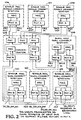
- FIG. 2 depicts the same FDDI ring as shown in FIG. 1 with an error in the secondary ring between FDDI stations 103 and 104.
- FIG. 3a depicts the preferred embodiment of the FDDI bit error rate tester of the invention while FIG. 3b depicts logic suitable for generating error event signals according to the preferred method for generating said signals.
- FIG. 4 depicts the timing and event sequence used by the methods taught herein, for generating an error event signal via the hardware shown in FIG. 3 and 3b. More particularly, the timing diagram of FIG. 4 shows an error event being detected, signalled and isolated in FDDI station 103 of FIG. 2 and further shows that the error does not propagate to FDDI station 102 of FIG. 2.
- FIG. 1 shows the configuration of a typical dual FDDI ring.
- Stations 101, 102 and 103 are all single MAC dual attachment stations.
- Station 104 is a dual MAC dual attachment station.
- Station 105 is a concentrator to which single MAC single attachment stations 106, 107 and 108 are attached.
- the primary ring is traced by a continuous line, shown as 120 in FIG. 1, and the secondary ring is traced by dotted line 130.
- the MAC and PHY layers in a given FDDI station are labeled along with the data path through each station being indicated. Finally, the primary and secondary inputs and outputs, to and from each station, are separately labeled.
- FIG. 2 shows the same ring where there is a fault in secondary ring 130 at the physical link between station 104 and station 103. Since the secondary ring does not have a connection to MAC in station 103, the MACs lost count mechanism is not able to detect and isolate the error.
- PHY A of station 103 puts out 4 symbols of HALT when it sees the violation symbol V in the midst of a frame, using its ENDEC transmit line as described in our copending US Patent 4, 835 776 and U.S. Patent Nos. 4,703,486 and 4,692,894 respectively, US 4, 835 776 is hereby incorporated by reference.
- Station 102 repeats the same 4 symbols of HALT.
- the new bit error rate tester in station 103 preferably in the SMT layer (not shown) parallel to the MAC and PHY A and PHY B, alone counts the error and isolates the fault.
- FIGS. 3a and 3b show the logic of the FDDI bit error rate tester (BERT). It consists of timer 301, error counter 302, storage device 303 (e.g., a register) and some discrete logic. Timer 301 is used to time the time duration for the error count. The timer value and maximum error count can be programmed by signals on lines 310 and 311 respectively. Whenever Quiet, Halt or Master line state conditions arise, or whenever a reset signal is generated by the system (e.g., the SMAP layer), timer 301 is reset. Timer 301 is also reset by internal BERT signals generated whenever the timer is full or when the error count (to be explained hereinafter) reaches a programmable maximum value. The reset mechanism for counter 301 may be seen with reference to OR gate 350 in FIG. 3a.
- the clocking for the logic shown in FIGS. 3a and 3b is a byteclock (BCLK) signal.
- the timer is enabled during active or idle line state conditions as may be seen with reference to OR gate 375.
- Error counter 302 is reset at the same time as timer 301 and is enabled on the occurrence of an error event.
- An error event is defined to occur (according to the preferred embodiment of the invention) upon the occurrence of 4 consecutive LSU (Line State Unknown) when in Active Line State or upon the occurrence of a single LSU during idle line state conditions.
- the error count is stored in register 303 so that at any particular instant, both the previous error count and the current error count is available for the upper management.
- station 103 did not have the bit error rate tester of the invention, the fault would propagate all the way to station 105's MAC (in the concentrator) in FIG. 2. Hence the fault would not get localized. Clearly the BERT located in station 103 immediately isolates the fault before propagation of the error is possible.
- the first station seeing the noise byte can count that towards noise count for the purpose of continuous link quality monitoring.
- Other downstream stations only see the IDLES because of the repeat filter in the noisy station. Hence the fault is again localized for an IDLE ring.
- the BERT can signal to the upper management that the link is not usable when the error count exceeds a specified limit within the programmed maximum timer value. This is accomplished via gate 390 shown in FIG. 3a.
- the time duration has to be 2.5 times the time interval for which an error estimate is being calculated. This is because there are 16 data symbols, one QUIET, five HALTs, and 4 VIOLATION symbols in the FDDI coding table. Hence the probability of data getting converted to noise is approximately 0.4.
- the bit error test duration should therefore be increased 2.5 times the normal bit error test duration.
- the test duration should be increased by 2.5 times to 1000 million byte clocks to see a violation error symbol. To average this over twice the test duration, the time to check for greater then two errors is 2000 million clock, or 31 bits of counter length.
- the byte counter (timer) for the preferred embodiment of the invention is 31 bits long.
- FIG. 3b shows a combination of D flip-flops, AND gates and an OR gate for signalling an error event to error counter 302 (of FIG. 3a) upon the occurrence of 4 LSUs in the ALS or the occurrence of 1 LSU in the ILS.
- FIG. 4 is a timing diagram depicting the operation of station 103 and 102 of FIG. 2 in the face of the fault between station 103 and 104.
- the Receive Bus (the link between PHY B and PHY A in station 103) of the ENDEC in PHYB of station 103 is shown, in FIG. 4, to have received the symbols II, JK, DD, VV, non II, non II and XXs (don't care symbols), in the order shown.
- the ALS output of the ENDEC in PHY B of station 103 goes high.
- Data (DD) follows and upon recognition of a violation (VV), LSU goes high and ALS goes low.
- the diagram in FIG. 4 shows the error event being signalled after 4 byte clocks of LSU following the ALS state. This is how the logic depicted in FIG. 3 b operates.
- FIG. 4 shows how station 102 does not have to signal an error, i.e., that the error was indeed isolated at station 103 (again, all with reference to FIG. 2).
- the Receive Bus for station 102 is shown with II, JK, DD, HH, HH, II, II and don't care symbols on the bus.
- the ALS signal generated by the ENDEC in PHY B of station 102 goes high upon seeing the JK delimiter. This stays high until LSU appears. LSU appears on the recognition of a violation symbol such as H, Q or V, as described by the FDDI specification.
Landscapes
- Engineering & Computer Science (AREA)
- Computer Networks & Wireless Communication (AREA)
- Signal Processing (AREA)
- Quality & Reliability (AREA)
- Environmental & Geological Engineering (AREA)
- Small-Scale Networks (AREA)
- Detection And Prevention Of Errors In Transmission (AREA)
- Maintenance And Management Of Digital Transmission (AREA)
- Dc Digital Transmission (AREA)
- Communication Control (AREA)
Claims (10)
- Dispositif pour effectuer la surveillance continue du taux d'erreurs sur des binaires au niveau de la couche physique (PHY) dans chaque noeud d'un réseau à passage de jeton à interface de données distribuées par fibres optiques (réseau FDDI) dans lequel chaque noeud dudit réseau comprend en outre une couche de gestion du réseau (SMT), une couche de commande d'accès au milieu de transmission (MAC), un générateur de signaux d'état de ligne pour produire un ensemble prédéterminé de signaux d'état de ligne dans des conditions prédéterminées, et un générateur de signaux d'horloge à multiplets pour produire des signaux de cadencement, comprenant :(a) des moyens logiques de testeur connectés audit générateur de signaux d'état de ligne pour fournir des signaux d'événements d'erreur en fonction d'un premier sous-ensemble dudit ensemble de signaux d'état de ligne, qui comprend un signal d'état de ligne active (ALS), un signal d'état de ligne inactive (ILS) et un signal d'état de ligne inconnu (LSU);(b) des moyens de compte d'erreurs à remise à l'état initial (302) connectés auxdits moyens logiques de testeur, validés chaque fois qu'un signal d'événement d'erreur est fourni par lesdits moyens logiques de testeur, pour accumuler un compte d'événements d'erreur, dans lesquels lesdits moyens de compte d'erreur comprennent des moyens (311) par lesquels ils peuvent être programmés en introduisant un signal d'entrée de compte maximal d'erreurs pour produire un signal de compte complet chaque fois que le compteur est validé et atteint le compte maximal d'erreurs avant d'être remis à l'état initial; et(c) des moyens de temporisateur à remise à l'état initial (301) connectés audit générateur de signaux d'état de ligne et audit générateur de signal d'horloge à multiplets, actionnables en fonction d'un deuxième sous-ensemble desdits signaux d'état de ligne pour accumuler une mesure du temps écoulé depuis la validation des moyens de temporisateur jusqu'à la remise à l'état initial des moyens de temporisateur, dans lesquels lesdits moyens de temporisateur comprennent des moyens (310) par lesquels ils peuvent être programmés en leur appliquant un signal d'entrée de temps écoulé maximal pour produire un signal d'expiration de temporisateur chaque fois que le temporisateur est validé et atteint ledit temps écoulé maximal avant d'être remis à l'état initial.
- Dispositif selon la revendication 1, comprenant en outre des moyens de mémorisation (303) connectés audit temporisateur et auxdits moyens de compte d'erreurs pour mémoriser ledit signal indicatif de compte d'événements d'erreur chaque fois que ledit signal d'expiration de temps est produit.
- Dispositif selon la revendication 2, comprenant en outre des moyens (390) pour détecter une liaison mauvaise, connectés audit temporisateur et auxdits moyens de compte d'erreurs, qui produisent un signal indiquant une liaison mauvaise si ledit signal de compte complet est produit avant l'expiration du temps.
- Dispositif selon la revendication 3, dans lequel ladite logique de testeur fournit un signal d'événement d'erreur lors de l'apparition de n signaux LSU dans l'ALS et m signaux LSU dans l'ILS.
- Dispositif selon la revendication 4, dans lequel n=4 et m=1.
- Dispositif selon la revendication 5, dans lequel ledit deuxième sous-ensemble dudit ensemble de signaux d'état de ligne comprend un signal d'état de ligne QUIET, un signal d'état de ligne HALT et un signal d'état de ligne MASTER.
- Dispositif selon la revendication 6, dans lequel lesdits moyens de testeur sont également remis à l'état initial en présence d'un signal quelconque parmi un ensemble de trois signaux comprenant ledit signal d'expiration de temps, ledit signal de compte complet et un signal extérieur de remise à l'état initial du système produit par des moyens de gestion supérieurs dans le réseau FDDI.
- Dispositif selon la revendication 7, dans lequel la détection et l'isolement d'une liaison mauvaise sont effectuées indépendamment de ladite couche MAC.
- Procédé pour isoler des défauts dans un réseau à passage de jeton du type FDDI à grande vitesse de transmission, comprenant les étapes consistant à:(a) utiliser des informations d'état de ligne au niveau de la couche PHY du réseau FDDI pour détecter et signaler des événements d'erreur, y compris le comptage de n apparitions de l'état de ligne inconnu (LSU) dans l'état de ligne active (ALS) et compter m apparitions de LSU dans l'état de ligne inactive (ILS) avant de signaler un événement d'erreur;(b) fournir un signal d'événement d'erreur pour chaque événement d'erreur détecté;(c) prévoir un intervalle de surveillance prédéterminé commençant en fonction d'un ensemble de signaux d'état de ligne et finissant ensuite après un temps maximal prédéterminé;(d) compter les événements d'erreur signalés dans ledit intervalle prédéterminé de surveillance pour produire un compte d'erreurs accumulées;(e) mémoriser périodiquement ladite valeur de compte d'erreurs accumulées;(f) comparer ledit compte d'erreurs accumulées à une valeur maximale présélectionnée de compte d'erreurs pour produire un signal de compte complet lorsque ledit compte d'erreurs accumulées atteint ladite valeur maximale présélectionnée de compte d'erreurs;(g) signaler une liaison mauvaise aux moyens supérieurs de gestion de réseau FDDI chaque fois que ledit compte d'erreurs accumulées est égal à ladite valeur maximale présélectionnée de compte d'erreurs avant l'expiration de l'intervalle de surveillance.
- Procédé selon la revendication 9, dans lequel n=4 et m=1.
Applications Claiming Priority (2)
| Application Number | Priority Date | Filing Date | Title |
|---|---|---|---|
| US07/173,325 US5023872A (en) | 1988-03-25 | 1988-03-25 | FDDI bit error rate tester |
| US173325 | 1993-12-23 |
Publications (3)
| Publication Number | Publication Date |
|---|---|
| EP0334510A2 EP0334510A2 (fr) | 1989-09-27 |
| EP0334510A3 EP0334510A3 (fr) | 1991-09-11 |
| EP0334510B1 true EP0334510B1 (fr) | 1995-12-20 |
Family
ID=22631514
Family Applications (1)
| Application Number | Title | Priority Date | Filing Date |
|---|---|---|---|
| EP89302328A Expired - Lifetime EP0334510B1 (fr) | 1988-03-25 | 1989-03-09 | Testeur de taux d'erreur de bits dans un réseau FDDI |
Country Status (5)
| Country | Link |
|---|---|
| US (1) | US5023872A (fr) |
| EP (1) | EP0334510B1 (fr) |
| JP (1) | JP2733512B2 (fr) |
| AT (1) | ATE131981T1 (fr) |
| DE (1) | DE68925140T2 (fr) |
Cited By (1)
| Publication number | Priority date | Publication date | Assignee | Title |
|---|---|---|---|---|
| DE29901302U1 (de) * | 1999-01-26 | 2000-03-30 | Siemens AG, 80333 München | Netzwerkteilnehmer |
Families Citing this family (43)
| Publication number | Priority date | Publication date | Assignee | Title |
|---|---|---|---|---|
| US6304987B1 (en) * | 1995-06-07 | 2001-10-16 | Texas Instruments Incorporated | Integrated test circuit |
| US5353308A (en) * | 1990-08-06 | 1994-10-04 | Texas Instruments Incorporated | Event qualified test methods and circuitry |
| JP3005250B2 (ja) * | 1989-06-30 | 2000-01-31 | テキサス インスツルメンツ インコーポレイテツド | バスモニター集積回路 |
| EP0470803B1 (fr) * | 1990-08-06 | 1997-06-18 | Texas Instruments Incorporated | Architecture de test qualifiée par l'événement |
| FR2682245B1 (fr) * | 1991-10-08 | 1994-07-29 | Bull Sa | Systeme de test d'un reseau en forme d'anneau a tres haut debit et procede de mise en óoeuvre de ce systeme. |
| CA2081036C (fr) * | 1991-12-19 | 1999-08-03 | Ahmed Hashem Abdelmonem | Methode et appareil de prediction d'erreurs et defaut de transmission |
| CA2064541C (fr) * | 1992-03-31 | 1998-09-15 | Thomas A. Gray | Comptage cyclique des erreurs pour la maintenance d'une liaison |
| US5539727A (en) * | 1992-04-14 | 1996-07-23 | Kramarczyk; Marian | Method and apparatus for configuring and maintaining token ring networks |
| US5351242A (en) * | 1992-04-14 | 1994-09-27 | Marian Kramarczyk | Method and apparatus for configuring and maintaining token ring networks |
| US5872780A (en) * | 1992-05-21 | 1999-02-16 | Alcatel Network Systems, Inc. | Sonet data transfer protocol between facility interfaces and cross-connect |
| US5355124A (en) * | 1992-06-09 | 1994-10-11 | Digital Equipment Corporation | Wiring concentrator for data networks |
| US5483542A (en) * | 1993-01-28 | 1996-01-09 | At&T Corp. | Byte error rate test arrangement |
| US5289473A (en) * | 1993-01-28 | 1994-02-22 | At&T Bell Laboratories | Method for determining byte error rate |
| US5390326A (en) * | 1993-04-30 | 1995-02-14 | The Foxboro Company | Local area network with fault detection and recovery |
| US5459731A (en) * | 1993-06-24 | 1995-10-17 | National Semiconductor Corporation | Link error monitoring |
| US5566203A (en) * | 1993-06-24 | 1996-10-15 | National Semiconductor Corp. | Intelligent repeater functionality |
| US5465250A (en) * | 1993-06-24 | 1995-11-07 | National Semiconductor Corporation | Hybrid loopback for FDDI-II slave stations |
| US5875210A (en) * | 1993-06-24 | 1999-02-23 | National Semiconductor Corporation | Method and apparatus for repeating data |
| US5394390A (en) * | 1993-10-29 | 1995-02-28 | International Business Machines Corporation | FDDI network test adapter history store circuit (HSC) |
| US5862145A (en) * | 1996-09-12 | 1999-01-19 | Advanced Micro Devices, Inc. | Method and system for identifying an error condition due to a faulty cable connection in an ethernet network |
| US6408413B1 (en) | 1998-02-18 | 2002-06-18 | Texas Instruments Incorporated | Hierarchical access of test access ports in embedded core integrated circuits |
| US6405335B1 (en) | 1998-02-25 | 2002-06-11 | Texas Instruments Incorporated | Position independent testing of circuits |
| US6690650B1 (en) * | 1998-02-27 | 2004-02-10 | Advanced Micro Devices, Inc. | Arrangement in a network repeater for monitoring link integrity by monitoring symbol errors across multiple detection intervals |
| US6728216B1 (en) * | 1998-02-27 | 2004-04-27 | Advanced Micro Devices, Inc. | Arrangement in a network repeater for monitoring link integrity and selectively down shifting link speed based on local configuration signals |
| US8184677B1 (en) * | 1998-02-27 | 2012-05-22 | Globalfoundries Inc. | Arrangement in a network repeater for monitoring link integrity and automatically down shifting link speed |
| US6097732A (en) * | 1998-10-30 | 2000-08-01 | Advanced Micro Devices, Inc. | Apparatus and method for controlling transmission parameters of selected home network stations transmitting on a telephone medium |
| US7058862B2 (en) | 2000-05-26 | 2006-06-06 | Texas Instruments Incorporated | Selecting different 1149.1 TAP domains from update-IR state |
| US7778259B1 (en) | 1999-05-14 | 2010-08-17 | Dunti Llc | Network packet transmission mechanism |
| US6912196B1 (en) * | 2000-05-15 | 2005-06-28 | Dunti, Llc | Communication network and protocol which can efficiently maintain transmission across a disrupted network |
| US6728915B2 (en) | 2000-01-10 | 2004-04-27 | Texas Instruments Incorporated | IC with shared scan cells selectively connected in scan path |
| US6769080B2 (en) | 2000-03-09 | 2004-07-27 | Texas Instruments Incorporated | Scan circuit low power adapter with counter |
| EP1326357A1 (fr) * | 2002-01-08 | 2003-07-09 | Siemens Aktiengesellschaft | Procédé pour déterminer et maintenir un débit prédéterminé de bit via une connexion filaire |
| US7428669B2 (en) * | 2003-12-07 | 2008-09-23 | Adaptive Spectrum And Signal Alignment, Inc. | Adaptive FEC codeword management |
| US8458453B1 (en) | 2004-06-11 | 2013-06-04 | Dunti Llc | Method and apparatus for securing communication over public network |
| US7308371B2 (en) * | 2004-06-15 | 2007-12-11 | Intel Corporation | Bit error rate testing for high-speed devices |
| US7813420B2 (en) * | 2005-06-02 | 2010-10-12 | Adaptive Spectrum And Signal Alignment, Inc. | Adaptive GDFE |
| US7817745B2 (en) * | 2005-06-02 | 2010-10-19 | Adaptive Spectrum And Signal Alignment, Inc. | Tonal precoding |
| US20140369480A1 (en) | 2013-06-12 | 2014-12-18 | Adaptive Spectrum And Signal Alignment, Inc. | Systems, methods, and apparatuses for implementing a dsl system |
| US8204074B2 (en) * | 2006-06-07 | 2012-06-19 | Broadcom Corporation | Flexible MAC/PHY association |
| US8683572B1 (en) | 2008-01-24 | 2014-03-25 | Dunti Llc | Method and apparatus for providing continuous user verification in a packet-based network |
| US7921336B1 (en) * | 2008-02-27 | 2011-04-05 | Netapp, Inc. | System and method for avoiding categorizing potential link error events as actual link error events based on a proximity to a physical layer signal state change |
| US10997007B2 (en) * | 2019-08-28 | 2021-05-04 | Mellanox Technologies, Ltd. | Failure prediction system and method |
| CN111949468B (zh) * | 2020-09-18 | 2023-07-18 | 苏州浪潮智能科技有限公司 | 一种双端口盘管理方法、装置、终端及存储介质 |
Family Cites Families (4)
| Publication number | Priority date | Publication date | Assignee | Title |
|---|---|---|---|---|
| ATE7439T1 (de) * | 1980-11-13 | 1984-05-15 | Hasler Ag | Verfahren zum funktionsfaehighalten einer digitalen nachrichtenuebertragungseinrichtung und anwendung desselben. |
| JPS60187160A (ja) * | 1984-03-07 | 1985-09-24 | Fujitsu Ltd | ル−プ伝送路障害通知方式 |
| US4703486A (en) * | 1984-12-18 | 1987-10-27 | Advanced Micro Devices, Inc. | Communication data encoder/decoder component system architecture |
| JPS61285852A (ja) * | 1985-06-12 | 1986-12-16 | Fujitsu Ltd | エラ−監視方式 |
-
1988
- 1988-03-25 US US07/173,325 patent/US5023872A/en not_active Expired - Lifetime
-
1989
- 1989-03-09 DE DE68925140T patent/DE68925140T2/de not_active Expired - Fee Related
- 1989-03-09 AT AT89302328T patent/ATE131981T1/de not_active IP Right Cessation
- 1989-03-09 EP EP89302328A patent/EP0334510B1/fr not_active Expired - Lifetime
- 1989-03-24 JP JP1073693A patent/JP2733512B2/ja not_active Expired - Lifetime
Cited By (1)
| Publication number | Priority date | Publication date | Assignee | Title |
|---|---|---|---|---|
| DE29901302U1 (de) * | 1999-01-26 | 2000-03-30 | Siemens AG, 80333 München | Netzwerkteilnehmer |
Also Published As
| Publication number | Publication date |
|---|---|
| ATE131981T1 (de) | 1996-01-15 |
| EP0334510A2 (fr) | 1989-09-27 |
| JPH0215744A (ja) | 1990-01-19 |
| DE68925140D1 (de) | 1996-02-01 |
| DE68925140T2 (de) | 1996-07-18 |
| US5023872A (en) | 1991-06-11 |
| EP0334510A3 (fr) | 1991-09-11 |
| JP2733512B2 (ja) | 1998-03-30 |
Similar Documents
| Publication | Publication Date | Title |
|---|---|---|
| US5023872A (en) | FDDI bit error rate tester | |
| US5381348A (en) | Token ring local area network testing apparatus using time delay reflectory | |
| US5642217A (en) | Apparatus for repowering and monitoring serial links | |
| CA2064541C (fr) | Comptage cyclique des erreurs pour la maintenance d'une liaison | |
| Bux et al. | Architecture and design of a reliable token-ring network | |
| EP0168258B1 (fr) | Système de transmission en boucle | |
| EP0254471B1 (fr) | Technique de détection de collisions pour un réseau local, optique, passif et en étoile utilisant le procédé CSMA/CD | |
| US5636203A (en) | Method and system for identifying fault locations in a communications network | |
| CA1254638A (fr) | Reseau local integre reconfigurable a grande vitesse | |
| US5444695A (en) | Token ring local area network testing apparatus providing station history information | |
| US20080228941A1 (en) | Ethernet Link Monitoring Channel | |
| US5365513A (en) | Token ring local area network testing apparatus for matching its speed to ring speed | |
| Strole | A local communications network based on interconnected token-access rings: A tutorial | |
| WO2011035640A1 (fr) | Procédé, système et appareil de diagnostic d'une panne de liaison physique descendante | |
| US5425017A (en) | Token ring local area network testing apparatus inserted in an active "T" co | |
| US6453432B1 (en) | Method and system for communicating the status of a digital transmission line element during loopback | |
| US5566203A (en) | Intelligent repeater functionality | |
| US5508998A (en) | Remote token ring beacon station detection and isolation | |
| Verissimo et al. | How hard is hard real-time communication on field-buses? | |
| Barranco et al. | CANcentrate: An active star topology for CAN networks | |
| Phinney et al. | Error handling in the IEEE 802 token-passing bus LAN | |
| KR0135213B1 (ko) | 소네트(sonet)신호 전송중 프레임 에러 감지 회로 | |
| Winkler et al. | Standards and architecture for token-ring local area networks | |
| Catania et al. | Enhancing reliability in an industrial LAN: design and performability evaluation | |
| CN121711280A (zh) | 一种多节点载波通信故障检测方法及系统 |
Legal Events
| Date | Code | Title | Description |
|---|---|---|---|
| PUAI | Public reference made under article 153(3) epc to a published international application that has entered the european phase |
Free format text: ORIGINAL CODE: 0009012 |
|
| AK | Designated contracting states |
Kind code of ref document: A2 Designated state(s): AT BE CH DE ES FR GB GR IT LI LU NL SE |
|
| PUAL | Search report despatched |
Free format text: ORIGINAL CODE: 0009013 |
|
| AK | Designated contracting states |
Kind code of ref document: A3 Designated state(s): AT BE CH DE ES FR GB GR IT LI LU NL SE |
|
| 17P | Request for examination filed |
Effective date: 19911216 |
|
| 17Q | First examination report despatched |
Effective date: 19930826 |
|
| GRAA | (expected) grant |
Free format text: ORIGINAL CODE: 0009210 |
|
| AK | Designated contracting states |
Kind code of ref document: B1 Designated state(s): AT BE CH DE ES FR GB GR IT LI LU NL SE |
|
| PG25 | Lapsed in a contracting state [announced via postgrant information from national office to epo] |
Ref country code: IT Free format text: LAPSE BECAUSE OF FAILURE TO SUBMIT A TRANSLATION OF THE DESCRIPTION OR TO PAY THE FEE WITHIN THE PRE;WARNING: LAPSES OF ITALIAN PATENTS WITH EFFECTIVE DATE BEFORE 2007 MAY HAVE OCCURRED AT ANY TIME BEFORE 2007. THE CORRECT EFFECTIVE DATE MAY BE DIFFERENT FROM THE ONE RECORDED.SCRIBED TIME-LIMIT Effective date: 19951220 Ref country code: BE Effective date: 19951220 Ref country code: CH Effective date: 19951220 Ref country code: AT Effective date: 19951220 Ref country code: NL Free format text: LAPSE BECAUSE OF FAILURE TO SUBMIT A TRANSLATION OF THE DESCRIPTION OR TO PAY THE FEE WITHIN THE PRESCRIBED TIME-LIMIT Effective date: 19951220 Ref country code: LI Effective date: 19951220 Ref country code: ES Free format text: THE PATENT HAS BEEN ANNULLED BY A DECISION OF A NATIONAL AUTHORITY Effective date: 19951220 Ref country code: GR Free format text: LAPSE BECAUSE OF FAILURE TO SUBMIT A TRANSLATION OF THE DESCRIPTION OR TO PAY THE FEE WITHIN THE PRESCRIBED TIME-LIMIT Effective date: 19951220 |
|
| REF | Corresponds to: |
Ref document number: 131981 Country of ref document: AT Date of ref document: 19960115 Kind code of ref document: T |
|
| REF | Corresponds to: |
Ref document number: 68925140 Country of ref document: DE Date of ref document: 19960201 |
|
| PG25 | Lapsed in a contracting state [announced via postgrant information from national office to epo] |
Ref country code: SE Effective date: 19960320 |
|
| PG25 | Lapsed in a contracting state [announced via postgrant information from national office to epo] |
Ref country code: LU Free format text: LAPSE BECAUSE OF NON-PAYMENT OF DUE FEES Effective date: 19960331 |
|
| ET | Fr: translation filed | ||
| NLV1 | Nl: lapsed or annulled due to failure to fulfill the requirements of art. 29p and 29m of the patents act | ||
| PLBE | No opposition filed within time limit |
Free format text: ORIGINAL CODE: 0009261 |
|
| STAA | Information on the status of an ep patent application or granted ep patent |
Free format text: STATUS: NO OPPOSITION FILED WITHIN TIME LIMIT |
|
| 26N | No opposition filed | ||
| PGFP | Annual fee paid to national office [announced via postgrant information from national office to epo] |
Ref country code: FR Payment date: 20010301 Year of fee payment: 13 |
|
| PGFP | Annual fee paid to national office [announced via postgrant information from national office to epo] |
Ref country code: DE Payment date: 20010330 Year of fee payment: 13 |
|
| REG | Reference to a national code |
Ref country code: GB Ref legal event code: IF02 |
|
| PGFP | Annual fee paid to national office [announced via postgrant information from national office to epo] |
Ref country code: GB Payment date: 20020205 Year of fee payment: 14 |
|
| PG25 | Lapsed in a contracting state [announced via postgrant information from national office to epo] |
Ref country code: DE Free format text: LAPSE BECAUSE OF NON-PAYMENT OF DUE FEES Effective date: 20021001 |
|
| PG25 | Lapsed in a contracting state [announced via postgrant information from national office to epo] |
Ref country code: FR Free format text: LAPSE BECAUSE OF NON-PAYMENT OF DUE FEES Effective date: 20021129 |
|
| REG | Reference to a national code |
Ref country code: FR Ref legal event code: ST |
|
| PG25 | Lapsed in a contracting state [announced via postgrant information from national office to epo] |
Ref country code: GB Free format text: LAPSE BECAUSE OF NON-PAYMENT OF DUE FEES Effective date: 20030309 |
|
| GBPC | Gb: european patent ceased through non-payment of renewal fee |
Effective date: 20030309 |