EP0334536B1 - Particle measuring apparatus - Google Patents
Particle measuring apparatus Download PDFInfo
- Publication number
- EP0334536B1 EP0334536B1 EP89302527A EP89302527A EP0334536B1 EP 0334536 B1 EP0334536 B1 EP 0334536B1 EP 89302527 A EP89302527 A EP 89302527A EP 89302527 A EP89302527 A EP 89302527A EP 0334536 B1 EP0334536 B1 EP 0334536B1
- Authority
- EP
- European Patent Office
- Prior art keywords
- measuring
- cell
- laser beam
- refractive index
- light
- Prior art date
- Legal status (The legal status is an assumption and is not a legal conclusion. Google has not performed a legal analysis and makes no representation as to the accuracy of the status listed.)
- Expired - Lifetime
Links
Images



Classifications
-
- G—PHYSICS
- G01—MEASURING; TESTING
- G01N—INVESTIGATING OR ANALYSING MATERIALS BY DETERMINING THEIR CHEMICAL OR PHYSICAL PROPERTIES
- G01N21/00—Investigating or analysing materials by the use of optical means, i.e. using sub-millimetre waves, infrared, visible or ultraviolet light
- G01N21/01—Arrangements or apparatus for facilitating the optical investigation
- G01N21/03—Cuvette constructions
- G01N21/05—Flow-through cuvettes
-
- G—PHYSICS
- G01—MEASURING; TESTING
- G01N—INVESTIGATING OR ANALYSING MATERIALS BY DETERMINING THEIR CHEMICAL OR PHYSICAL PROPERTIES
- G01N15/00—Investigating characteristics of particles; Investigating permeability, pore-volume or surface-area of porous materials
- G01N15/02—Investigating particle size or size distribution
- G01N15/0205—Investigating particle size or size distribution by optical means
-
- G—PHYSICS
- G01—MEASURING; TESTING
- G01N—INVESTIGATING OR ANALYSING MATERIALS BY DETERMINING THEIR CHEMICAL OR PHYSICAL PROPERTIES
- G01N21/00—Investigating or analysing materials by the use of optical means, i.e. using sub-millimetre waves, infrared, visible or ultraviolet light
- G01N21/01—Arrangements or apparatus for facilitating the optical investigation
- G01N21/03—Cuvette constructions
- G01N2021/0389—Windows
- G01N2021/0392—Nonplanar windows
-
- G—PHYSICS
- G01—MEASURING; TESTING
- G01N—INVESTIGATING OR ANALYSING MATERIALS BY DETERMINING THEIR CHEMICAL OR PHYSICAL PROPERTIES
- G01N21/00—Investigating or analysing materials by the use of optical means, i.e. using sub-millimetre waves, infrared, visible or ultraviolet light
- G01N21/17—Systems in which incident light is modified in accordance with the properties of the material investigated
- G01N21/47—Scattering, i.e. diffuse reflection
- G01N2021/4704—Angular selective
- G01N2021/4707—Forward scatter; Low angle scatter
-
- G—PHYSICS
- G01—MEASURING; TESTING
- G01N—INVESTIGATING OR ANALYSING MATERIALS BY DETERMINING THEIR CHEMICAL OR PHYSICAL PROPERTIES
- G01N21/00—Investigating or analysing materials by the use of optical means, i.e. using sub-millimetre waves, infrared, visible or ultraviolet light
- G01N21/17—Systems in which incident light is modified in accordance with the properties of the material investigated
- G01N21/47—Scattering, i.e. diffuse reflection
- G01N21/49—Scattering, i.e. diffuse reflection within a body or fluid
- G01N21/51—Scattering, i.e. diffuse reflection within a body or fluid inside a container, e.g. in an ampoule
- G01N2021/513—Cuvettes for scattering measurements
-
- G—PHYSICS
- G01—MEASURING; TESTING
- G01N—INVESTIGATING OR ANALYSING MATERIALS BY DETERMINING THEIR CHEMICAL OR PHYSICAL PROPERTIES
- G01N21/00—Investigating or analysing materials by the use of optical means, i.e. using sub-millimetre waves, infrared, visible or ultraviolet light
- G01N21/17—Systems in which incident light is modified in accordance with the properties of the material investigated
- G01N21/41—Refractivity; Phase-affecting properties, e.g. optical path length
- G01N21/4133—Refractometers, e.g. differential
-
- G—PHYSICS
- G01—MEASURING; TESTING
- G01N—INVESTIGATING OR ANALYSING MATERIALS BY DETERMINING THEIR CHEMICAL OR PHYSICAL PROPERTIES
- G01N2201/00—Features of devices classified in G01N21/00
- G01N2201/12—Circuits of general importance; Signal processing
- G01N2201/121—Correction signals
- G01N2201/1217—Correction signals for index of solution, carrying fluids
Definitions
- This invention relates to a particle measuring apparatus, and more particularly to a particle measuring apparatus in which a laser beam is projected into a measuring area in a fluid containing particles or particulates to be measured and light scattered from the particles is received and photoelectrically converted into an electrical signal to evaluate particle characteristics such as their size and the number of the particles.
- one apparatus employs the above mentioned technique in order to measure particle impurities in purified water.
- the measurement is, however, difficult because the particles in the purified water are very small in size and exist only rarely. Therefore, in order to increase the amount of light scattered by the individual particles, the laser beam from a laser source is focused at an area which is made as small as possible to obtain a high-luminance measuring area. The light scattered from the particles passing through this measuring area are received for measurement.
- Japanese Laid-Open Publication No. 18242/88 discloses one such system in which the projected light such as a laser beam is converged in the measuring area with a high convergence factor to increase the intensity of the light and make the light scattered from the particles more stronger in intensity.
- This measuring system also employs a mask having a small aperture to limit the measuring area as viewed from the light receiving side into a field so small as to be able to reduce the background light.
- this system is intended to reduce the background light and detect the light scattered from the particles smaller than 0.1 microns in diameter.
- an aperture on the mask is set to be smaller than a few tens of microns in diameter.
- optical particle measuring system such as the one described above have been applied to measure particle impurities in various kinds of fluids and chemical solutions such as for example, nitric acid or hydrofluoric acid whose refractive index is different from that of water.
- the change in refractive index of solutions disadvantageously causes a displacement of conjugate relation of the mask relative to the convergence point of the laser beam or condenser lens in the detecting system.
- this displacement has been adjusted mechanically by moving the mask or lens.
- This mechanical adjustment for displacement of the conjugate relation between the mask and the convergence point of the laser beam or the lens in light receiving means is impractical because this adjustment may cause another displacement of the optical axes and also because it requires a rather sophisticated high precision control unit.
- the refractive index of the fluid in the measuring cell varies too greatly, there is the possibility that it influences aberrations of the converging lens or condenser lens, thus greatly reducing the detecting capabilities of the apparatus.
- the change in refractive index of solutions also affects the scattering intensity, so that a correction is required when the refractive index changes greatly.
- a particle measuring apparatus in which a laser beam is projected into a measuring region in a fluid of a predetermined refractive index containing particles to be measured and light scattered from the particles is received and photoelectrically converted into an electrical signal to evaluate particle characteristics
- the apparatus comprising a measuring cell which contains the fluid which is caused to flow through the measuring region and which is formed with a first cell window for the projection of the laser beam therethrough and a second cell window through which the light scattered from the particles passes; a laser beam projector for projecting the laser beam through said first cell window, said laser beam being focused at a convergence point in the measuring region; the said second cell window having a spherical surface with a predetermined radius of curvature whose center is at the convergence point, light receiving means for receiving light which has been scattered from the particles in the measuring area through said second cell window and which has passed through a mask; and means for photoelectrically converting the received light into an electrical signal to evaluate characteristics of the particles.
- the present invention is characterised by apparatus for measuring the refractive index of the fluid in the measuring cell.
- the inner surface of the cell window defines at least such a spherical surface, but the outer surface may be also spherical with the same condition as that of the inner surface.
- both the cell window through which the laser beam is projected and that through which the scattered light passes are formed with the spherical surface with a predetermined radius of curvature whose center is positioned at the convergence point.
- the projected laser beam and/or the light scattered from the particles in the fluid travel along the normal line of the spherical surfaces formed on the measuring cell, so that no refractive function occurs due to the difference of refractive indexes between the cell window and the fluid in the measuring cell, thus causing no effect on the wave front.
- This allows a particle measurement with improved accuracy even if the refractive index of the fluid changes greatly.
- the conjugate relation between the position of the mask and the converegence point of the laser beam remains unchanged even if the refractive index of a fluid changes. Furthermore, this has no influence on the aberration of the lenses, thus assuring a highly precise measurement also for particles contained in any kind of fluid of different refractive index.
- the apparatus according to the invention also makes the measurement of the refractive index of the fluid possible, thus allowing a correction for the change in scattering intensity caused by the change in refractive index of the fluid.
- FIGS 1A and 1B are schematic representations showing the basic principles and functions of the present invention, in which reference numeral 23 denotes a measuring cell containing a fluid (either liquid or gaseous ) and reference numeral 21 a measuring cell window.
- the fluid contains particles or particulates to be measured.
- the measuring cell window including a window through which a laser beam is projected and/or a window through which laser light scattered from the particles passes defines a spherical surface with a predetermined radius of curvature whose center is set to a point a on which the laser beam is focused.
- the necessary condition is that at least a spherical inner surface r2 of the measuring cell window 21 has a radius r2 of curvature whose center lies at the focus point a of the measuring laser beam.
- both flat and spherical outer surface r1 may be formed in the measuring cell window, but, taking the eccentricity of the cell window into consideration, the spherical surface r1 may be preferable with a radius curvature r1 whose center lies also on the convergence point a .
- laser light from a laser light source (not shown) is projected through a spherical surface window 5 of a measuring cell 4 and converges at a convergence point a within the measuring cell 4 by means of a converging lens L1 in a laser beam projector 1.
- the measuring laser beam is transmitted to a monitoring optical system 3 which includes a spherical surfaced cell window 17.
- the optical system of the laser beam projector 1 may further include an expander lens (not shown) and other lenses arranged so as to provide desired beam waist and convergence characteristics.
- the monitor optical system 3 functions to detect power fluctuations in the laser and to monitor the alignment of the axis of the laser beam projector.
- the monitor system is provided so as to allow automatic compensations to be made in accordance with power fluctuations in the laser light source. Further, the monitor system 3 outputs an error message when the measuring beam becomes misaligned.
- the fluid (either liquid or gaseous) containing the particles or particulates to be measured is introduced into and drained from the measuring cell 4 in such a manner as to flow past the convergence point a in the measuring area.
- the fluid may be introduced in any number of directions.
- the flow path of the fluid may be arranged so as to coaxial to the measuring laser beam, may be perpendicular thereto, may be parallel to the axis of the scattered light detecting means or perpendicular thereto, that is, perpendicular to the plane of paper.
- the fluid may preferably be introduced so that the flow path is oblique at a predetermined angle with respect to the above-mentioned directions.
- a particle suspended in the fluid in the measuring cell passes through the convergence point a of the measuring laser beam, it scatters the laser beam.
- a portion of the scattered laser beam passes through a light receiving system 2 and converges on an aperture of a mask M so as to form an image of the convergence point a thereon.
- the portion of the light that passes through the aperture of the mask M is incident on a photoelectric detector 7 comprised of, for example, a photomultiplier.
- the measuring cell windows 5, 6 and 17 are all of the variety in which they have a spherical surface whose center of radius of curvature is at the convergence point a in the measuring cell.
- the most critical window is the window 6 through which the scattered laser light passes, so that it is preferable that at least the window 6 may be formed with a spherical surface in accordance with the invention.
- a sampling unit 8 for integrating in unit sampling intervals photoelectric pulses which are produced from the photoelectric detector 7, corresponding to the intensity of the scattered light.
- the output of the sampling unit 8 is then fed to a writing unit 9 for writing values counted in sampling intervals as time series data.
- the time series data from the writing unit 9 are stored in a time series data memory 10.
- a central processing unit is further provided which controls the time series data memory 10, a ROM for storing programs and a work area memory (RAM) 12 for storing processed data.
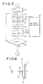
- Figure 3 shows a flow chart which illustrates how the apparatus according to the invention operates.
- the laser beam 22 is converged on the point a through the spherical cell window 5.
- the fluid containing the particles to be measured is caused to pass through a particle measuring area including the convergence point a at its center.
- the light scattered from the particles in the measuring area passes through the spherical cell window 6 and is focused on the the mask M by means of the converging lens L2.
- the scattered light passing through the mask aperture impinges on the photoelectric detector 7.
- the photoelectric pulses corresponding to the scattered light and produced from the photoelectric detector 7 are integrated in unit sampling intervals by means of the sampling unit 8 and then stored in the time series data memory 10.
- the photoelectric detector is comprised of a photomultiplier type photon counter
- the photosensing unit is subject to probability related fluctuations due to its extremely high sensitivity. Therefore, running average calculations are performed for the data in the memory 10 in order to determine the average light intensity at the position of the mask M as shown in Figure 3.
- step S1 After initiating the process at step S1 the address from which data is to be read out is incremented at step S2.
- step S3 k data from the n-th data are read out from the memory 10.
- step S4 an average operation is performed for the k data.
- the data for which the average operation is carried out are returned for storage to the address n in the time series data memory 10 at step S5. This process is repeated to effect the running average for the time series data stored until n>N-k+1 is satisfied at Step S6, wherein N is the total number of data.
- the spherical surface of the measuring cell window has a radius of curvature whose center is set to coincide with the convergence point a in the measuring cell.
- the laser beam thus can advance along the normal of the spherical surface even if the refractive index of the fluid in the measurement cell changes, thus assuring a particle measurement with high accuracy without any refraction.
- the change in the refractive index of the fluid causes a change in focal length of the entire optical system including the radius r1 of curvature of the outer surface and the radius r2 of curvature of the inner surface in the measuring cell. This also causes a change in spot size of the laser beam at the convergence point and a change in magnification factor of the lens for an image projected on the mask M.
- f0 is the focal length of the entire system for the measuring cell full of air (1.0 refractive index) and f n the focal length of the entire system for the measuring cell having the refractive index n of the fluid.
- f n f0/n (1) holds.
- ⁇ 0' ⁇ 0/n (2) wherein ⁇ 0 is the beam waist diameter when the measuring cell is full of air and ⁇ 0′ the beam waist diameter when the refractive index of the fluid in the cell is n.
- the apparatus according to the invention is provided with an optical system for measuring the refractive index as shown in Figures 4 and 5.
- a pin hole 15 illuminated by a light source 14 such as a light emitting diode or the like is focused on a pin hole 19 by a lens L3 through a flat cell window 16, the measuring cell 4 and a flat cell window 18, the pin holes 15, 19 being disposed on opposite sides of and outside the measuring cell 4.
- the image of the pin hole 15 with its amount of light limited by the aperture of the pin hole 19 reaches a photoelectric converter 20 such as a photodiode or the like.
- the pin hole 19 is constructed to be movable along the direction of the optical axis together with the photoelectric converter 20.When the refractive index in the cell changes, the pinhole 19 together with the photoelectric converter 20 is displaced to measure the refractive index.
- the image of the pin hole 15 and the aperture defined by the pin hole 19 assume a relationship in which the image of the pin hole 15 is larger than or equal to the aperture of the pin hole 19.
- the refractive index n can be calculated as follows:
- points F and F′ are the focal points of the lens L3 and the point P is an image of an object O formed by the lens L3.
- the pin hole 15 with a diameter M is located at the object point O and the photodiode 20 provided with the pin hole 19 having a diameter N is located at the image point P as shown in Figure 5.
- ⁇ n is always greater than or equal to ⁇ 0 for the refractive index n which is greater than or equal to 1.0. If the diameter N is now determined so as to be smaller than or equal to M ⁇ 0 , the diameter N is always smaller than or equal to M ⁇ n . Thus by moving the pin hole of the mask 19 to the point at which the best focus is obtained, the maximum detected light value is obtained and thus by determining this focal point the refractive index of the fluid in the cell may be determined.
- the pin hole mask 15 having an aperture diameter of M is formed by way of vapor deposition or by chromium plating on a transparent substrate 16 to interrupt the light from the light source other than the light passing through the aperture M.
- the substrate 16 may be comprised of a transparent material such as quartz, glass, pyrex or other suitable material.
- the pin hole 15 having the diameter M may alternatively be adhered to the planer surfaced window 16.
- the thus formed pin hole 15 is illuminated by the light source 14, which may be turned off or blinded by a shutter during the particle measurement.
- magnification of a projected image from the points O to P improves the accuracy in measurement. For this reason the magnification may be determined depending upon its demand. The too great magnification would, however, be not preferable because the focal depth is also too deep.
- the apparatus according to the invention is preferably provided with an optical system for measuring the refractive index for the purpose of correction.
- the apparatus according to the invention indeed needs an additional refractive index measuring system in comparison with the prior art apparatus, but no adjustment is advantageously required for the particle measuring apparatus and no lens aberration occurs even if fluctuations in the refractive index of the fluid takes place. This also means that fluctuations in the refractive index of the fluid can not be detected by means of the particle detecting optical system and thus the refractive index measuring system is additionally needed.
Landscapes
- Chemical & Material Sciences (AREA)
- Physics & Mathematics (AREA)
- Health & Medical Sciences (AREA)
- Life Sciences & Earth Sciences (AREA)
- Analytical Chemistry (AREA)
- Biochemistry (AREA)
- General Health & Medical Sciences (AREA)
- General Physics & Mathematics (AREA)
- Immunology (AREA)
- Pathology (AREA)
- Dispersion Chemistry (AREA)
- Investigating Or Analysing Materials By Optical Means (AREA)
Applications Claiming Priority (2)
| Application Number | Priority Date | Filing Date | Title |
|---|---|---|---|
| JP63068074A JP2635992B2 (ja) | 1988-03-24 | 1988-03-24 | 微粒子測定装置 |
| JP68074/88 | 1988-03-24 |
Publications (3)
| Publication Number | Publication Date |
|---|---|
| EP0334536A2 EP0334536A2 (en) | 1989-09-27 |
| EP0334536A3 EP0334536A3 (en) | 1990-12-19 |
| EP0334536B1 true EP0334536B1 (en) | 1994-02-16 |
Family
ID=13363260
Family Applications (1)
| Application Number | Title | Priority Date | Filing Date |
|---|---|---|---|
| EP89302527A Expired - Lifetime EP0334536B1 (en) | 1988-03-24 | 1989-03-15 | Particle measuring apparatus |
Country Status (4)
| Country | Link |
|---|---|
| US (1) | US5017008A (ja) |
| EP (1) | EP0334536B1 (ja) |
| JP (1) | JP2635992B2 (ja) |
| DE (1) | DE68913058T2 (ja) |
Families Citing this family (18)
| Publication number | Priority date | Publication date | Assignee | Title |
|---|---|---|---|---|
| JPH03107745A (ja) * | 1989-09-20 | 1991-05-08 | Mitsubishi Rayon Co Ltd | 光散乱測定方法およびその装置 |
| JPH0663964B2 (ja) * | 1990-09-05 | 1994-08-22 | 日本分光工業株式会社 | 微小流動セル |
| DE69129260T2 (de) * | 1990-11-03 | 1998-11-19 | Horiba Ltd | Gerät zur Messung der Teilchengrössenverteilung |
| US5235409A (en) * | 1991-08-13 | 1993-08-10 | Varian Associates, Inc. | Optical detection system for capillary separation columns |
| US5305073A (en) * | 1992-02-12 | 1994-04-19 | Precision Detectors, Inc. | Methods and apparatus for molecular characterization |
| US5383024A (en) * | 1992-08-12 | 1995-01-17 | Martin Marietta Energy Systems, Inc. | Optical wet steam monitor |
| US5701176A (en) * | 1995-07-28 | 1997-12-23 | Precision Detectors, Inc. | High temperature light scattering measurement device comprising a rigid extension tube |
| US6050693A (en) * | 1997-03-11 | 2000-04-18 | Virtek Vision Corporation | Collimator for laser projector |
| US6087182A (en) | 1998-08-27 | 2000-07-11 | Abbott Laboratories | Reagentless analysis of biological samples |
| US6104491A (en) * | 1998-12-14 | 2000-08-15 | Microtrac, Inc. | System for determining small particle size distribution in high particle concentrations |
| JP4574962B2 (ja) * | 2003-07-25 | 2010-11-04 | ワイアット テクノロジー コーポレイション | 小粒子の溶液を特徴付けるための方法および装置 |
| US7538874B2 (en) * | 2006-03-23 | 2009-05-26 | Hach Company | Measurement of light from a predefined scatter angle from particulate matter in a media |
| WO2009098867A1 (ja) * | 2008-02-07 | 2009-08-13 | Mitsui Engineering & Shipbuilding Co., Ltd. | 蛍光検出装置および蛍光検出方法 |
| EP3023770B1 (en) * | 2014-11-21 | 2017-12-27 | Anton Paar GmbH | Determination of a refractive index of a sample and of a particle size of particles in said sample by means of an apparatus for measuring light scattering |
| EP4050322B1 (en) * | 2016-08-04 | 2024-05-29 | Malvern Panalytical Limited | Method of characterising particles suspended in a fluid dispersant by light diffraction, processor and machine-readable, non-transient storage medium |
| DE102018206486A1 (de) | 2018-03-16 | 2019-09-19 | Leica Microsystems Cms Gmbh | Verfahren und Vorrichtung zum Manipulieren eines Strahlenganges in einem Mikroskop, Verfahren zur Aufnahme von Bilderstapeln in einem Mikroskop und nichtflüchtiges computerlesbares Speichermedium |
| JP2021535999A (ja) * | 2018-08-31 | 2021-12-23 | パーティクル・メージャーリング・システムズ・インコーポレーテッド | 流体屈折率最適化粒子計数器 |
| DE102018126002B4 (de) * | 2018-10-19 | 2020-10-08 | Leica Microsystems Cms Gmbh | Verfahren und Mikroskop zur Bestimmung des Brechungsindex eines optischen Mediums |
Family Cites Families (5)
| Publication number | Priority date | Publication date | Assignee | Title |
|---|---|---|---|---|
| CA1127867A (en) * | 1978-03-20 | 1982-07-20 | Albert Brunsting | Ellipsoid radiation collector and method |
| DE3000033A1 (de) * | 1979-01-02 | 1980-07-31 | Coulter Electronics | Verfahren und vorrichtung zum messen der richtungsverteilung der von einem teilchen zurueckgestrahlten strahlungsenergie zur teilchencharakterisierung |
| US4348107A (en) * | 1980-07-18 | 1982-09-07 | Coulter Electronics, Inc. | Orifice inside optical element |
| FR2566543B1 (fr) * | 1984-06-20 | 1988-02-26 | Commissariat Energie Atomique | Dispositif optique a rendement de collection eleve et cytofluorimetre en faisant application |
| DE3424108A1 (de) * | 1984-06-29 | 1986-01-09 | Bernhard Prof. Dr.-Ing. 4300 Essen Schrader | Probenanordnung zur spektrometrie, verfahren zur messung von lumineszenz und streuung und verwendung der probenanordnung |
-
1988
- 1988-03-24 JP JP63068074A patent/JP2635992B2/ja not_active Expired - Lifetime
-
1989
- 1989-03-15 EP EP89302527A patent/EP0334536B1/en not_active Expired - Lifetime
- 1989-03-15 DE DE68913058T patent/DE68913058T2/de not_active Expired - Lifetime
- 1989-03-23 US US07/328,030 patent/US5017008A/en not_active Expired - Lifetime
Also Published As
| Publication number | Publication date |
|---|---|
| JPH01242939A (ja) | 1989-09-27 |
| JP2635992B2 (ja) | 1997-07-30 |
| DE68913058D1 (de) | 1994-03-24 |
| EP0334536A2 (en) | 1989-09-27 |
| EP0334536A3 (en) | 1990-12-19 |
| US5017008A (en) | 1991-05-21 |
| DE68913058T2 (de) | 1994-06-30 |
Similar Documents
| Publication | Publication Date | Title |
|---|---|---|
| EP0334536B1 (en) | Particle measuring apparatus | |
| EP0649170B1 (en) | Semiconductor wafer inspection apparatus | |
| US10458781B2 (en) | Sample shape measuring method and sample shape measuring apparatus | |
| KR100474864B1 (ko) | 광 투과율 측정방법 및 그 장치 | |
| JP2641927B2 (ja) | 微粒子測定装置 | |
| GB2269667A (en) | Refractometer | |
| US4638168A (en) | Apparatus for measurement of hollow fiber dimensions | |
| US5636027A (en) | Apparatus for making contactless measurements of the thickness of an object made of transparent material | |
| US4397547A (en) | Lens module for an opto-electronic range finder | |
| US4893929A (en) | Particle analyzing apparatus | |
| US4792695A (en) | Contact-free measuring apparatus having an F-theta-corrected, catadioptric objective and method for using the same | |
| US6819419B2 (en) | Method for illuminating particles contained in a medium for optical analysis, and optical particle analyser | |
| US4707132A (en) | Process for sensing defects on a smooth cylindrical interior surface in tubing | |
| EP0538031A2 (en) | Method and device for detecting an interface | |
| JPH0418618B2 (ja) | ||
| JPS6129737A (ja) | 粒子解析装置 | |
| JP2002257706A (ja) | 光散乱測定プローブ | |
| JPS63292039A (ja) | 液体中微粒子検出装置 | |
| JP3516535B2 (ja) | 粒子分析装置 | |
| JPH08136440A (ja) | 流れ粒子分析装置及びその装置の光軸の位置合せ方法 | |
| JPS6370110A (ja) | 距離測定装置 | |
| JPS63263412A (ja) | 非接触変位計 | |
| JPH07169071A (ja) | 焦点エラー検出用光ピックアップシステム | |
| JPS5937405A (ja) | 光電式測定装置 | |
| SU914942A1 (ru) | Фотометр рассеянного света 1 |
Legal Events
| Date | Code | Title | Description |
|---|---|---|---|
| PUAI | Public reference made under article 153(3) epc to a published international application that has entered the european phase |
Free format text: ORIGINAL CODE: 0009012 |
|
| AK | Designated contracting states |
Kind code of ref document: A2 Designated state(s): CH DE FR GB IT LI |
|
| PUAL | Search report despatched |
Free format text: ORIGINAL CODE: 0009013 |
|
| AK | Designated contracting states |
Kind code of ref document: A3 Designated state(s): CH DE FR GB IT LI |
|
| 17P | Request for examination filed |
Effective date: 19910529 |
|
| 17Q | First examination report despatched |
Effective date: 19921127 |
|
| GRAA | (expected) grant |
Free format text: ORIGINAL CODE: 0009210 |
|
| AK | Designated contracting states |
Kind code of ref document: B1 Designated state(s): CH DE FR GB IT LI |
|
| ITF | It: translation for a ep patent filed | ||
| REF | Corresponds to: |
Ref document number: 68913058 Country of ref document: DE Date of ref document: 19940324 |
|
| ET | Fr: translation filed | ||
| PLBE | No opposition filed within time limit |
Free format text: ORIGINAL CODE: 0009261 |
|
| STAA | Information on the status of an ep patent application or granted ep patent |
Free format text: STATUS: NO OPPOSITION FILED WITHIN TIME LIMIT |
|
| 26N | No opposition filed | ||
| REG | Reference to a national code |
Ref country code: GB Ref legal event code: IF02 |
|
| REG | Reference to a national code |
Ref country code: CH Ref legal event code: PFA Owner name: KOWA COMPANY, LTD Free format text: KOWA COMPANY, LTD#6-29, NISHIKI 3-CHOME#NAKA-KU/NAGOYA-SHI/AICHI-KEN (JP) -TRANSFER TO- KOWA COMPANY, LTD#6-29, NISHIKI 3-CHOME#NAKA-KU/NAGOYA-SHI/AICHI-KEN (JP) |
|
| PGFP | Annual fee paid to national office [announced via postgrant information from national office to epo] |
Ref country code: CH Payment date: 20080225 Year of fee payment: 20 |
|
| PGFP | Annual fee paid to national office [announced via postgrant information from national office to epo] |
Ref country code: IT Payment date: 20080313 Year of fee payment: 20 Ref country code: GB Payment date: 20080310 Year of fee payment: 20 |
|
| PGFP | Annual fee paid to national office [announced via postgrant information from national office to epo] |
Ref country code: DE Payment date: 20080229 Year of fee payment: 20 Ref country code: FR Payment date: 20080221 Year of fee payment: 20 |
|
| REG | Reference to a national code |
Ref country code: CH Ref legal event code: PL |
|
| REG | Reference to a national code |
Ref country code: GB Ref legal event code: PE20 Expiry date: 20090314 |
|
| PG25 | Lapsed in a contracting state [announced via postgrant information from national office to epo] |
Ref country code: GB Free format text: LAPSE BECAUSE OF EXPIRATION OF PROTECTION Effective date: 20090314 |