EP0334556A1 - Öfen - Google Patents
Öfen Download PDFInfo
- Publication number
- EP0334556A1 EP0334556A1 EP89302660A EP89302660A EP0334556A1 EP 0334556 A1 EP0334556 A1 EP 0334556A1 EP 89302660 A EP89302660 A EP 89302660A EP 89302660 A EP89302660 A EP 89302660A EP 0334556 A1 EP0334556 A1 EP 0334556A1
- Authority
- EP
- European Patent Office
- Prior art keywords
- muffle
- sledge
- furnace according
- furnace
- gas
- Prior art date
- Legal status (The legal status is an assumption and is not a legal conclusion. Google has not performed a legal analysis and makes no representation as to the accuracy of the status listed.)
- Withdrawn
Links
Images

Classifications
-
- F—MECHANICAL ENGINEERING; LIGHTING; HEATING; WEAPONS; BLASTING
- F27—FURNACES; KILNS; OVENS; RETORTS
- F27B—FURNACES, KILNS, OVENS OR RETORTS IN GENERAL; OPEN SINTERING OR LIKE APPARATUS
- F27B9/00—Furnaces through which the charge is moved mechanically, e.g. of tunnel type; Similar furnaces in which the charge moves by gravity
- F27B9/30—Details, accessories or equipment specially adapted for furnaces of these types
- F27B9/3005—Details, accessories or equipment specially adapted for furnaces of these types arrangements for circulating gases
-
- F—MECHANICAL ENGINEERING; LIGHTING; HEATING; WEAPONS; BLASTING
- F27—FURNACES; KILNS; OVENS; RETORTS
- F27D—DETAILS OR ACCESSORIES OF FURNACES, KILNS, OVENS OR RETORTS, IN SO FAR AS THEY ARE OF KINDS OCCURRING IN MORE THAN ONE KIND OF FURNACE
- F27D7/00—Forming, maintaining or circulating atmospheres in heating chambers
Definitions
- the invention relates to furnaces.
- Conveyer furnaces have been previously proposed comprising a muffle with an endless conveyer belt extending therethrough and heating means. Articles placed on the conveyer belt and conveyed through the muffle are heated and may thereby be dried and/or fired.
- the articles may for example comprise ceramic substrates to form printed circuits and may have printing thereon.
- Difficulty may be experienced in obtaining a pure atmosphere within a furnace. This may be caused by binding and brazing materials which are used in electrical circuit component manufacture breaking down under high temperature and causing contamination of the furnace. This problem is particularly prevalent in furnaces designed and manufactured for the micro-electronics industry and may cause unacceptable contamination of components leading to rejection thereof and consequent financial loss.
- a furnace having a muffle, an endless conveyer belt extending through the muffle and heating means, wherein adjacent an entry end of the muffle means are provided for supplying gas to and extracting gas from a volume above a determined length of the conveyer belt within the muffle thereby to cause turbulence in the atmosphere within said volume and extract contaminants therefrom.
- the gas may be atmospheric air or if desired may be an inert gas.
- the gas is fed into the furnace under positive pressure and exhausted under negative pressure. Removal of contaminants from said volume may render the entire furnace free from contamination.
- said means comprise a sledge which can slide in spaced apart sledge tracks provided one on each side of the conveyer belt adjacent the side walls of the muffle, the tracks also acting to guide the conveyor belt therebetween.
- the sledge may comprise a positive pressure ladder and a variable negative pressure plenum supported by runners. The runners support the ladder and plenum and elevate them above the belt so that they span the belt width and extend longitudinally for the initial heating zones of the furnace.
- the pressure ladder may comprise parallel supply tubes with interspersed pressure feed tubes drilled in staggered form with outlet holes at 45% to the horizontal. The ladder may be supported on crossbars fixed to runners of the sledge.
- the plenum may, preferably together with a further plenum, be provided above the positive pressure ladder.
- the sledge may comprise a Bern vent providing additional atmosphere separation and may be driven by a flow meter controlled bladeless fan with a 25:1 ratio.
- a magnahelic gauge or manometer may be connected to the input end of the Bern unit.
- the sledge is readily retractable from the furnace upon disconnection of gas supply and extraction lines.
- the sledge may be extracted as a total unit or the pressure ladder may be removed independently to facilitate cleaning and/or modification.
- the inner end of the sledge is fitted with a diverter blade which can be angularly adjusted to promote atmosphere separation.
- said means is coupled to a powered vent box, the vent box being demountable for cleaning.
- the vent box may support a guard which will prevent insertion of a hand into the entrance of the muffle when said means is in a retracted position.
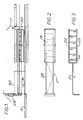
- a furnace has a muffle 1, Figure 4, comprising side walls 2, 3 a roof formed by inclined members 4, 5 and a base which laterally comprises inturned portions 6, 7 of the side walls 2, 3 and upturned portions 8, 9.
- a heating plenum 10 is provided between horizontal plates 11, 12, the plate 12 having a supply pipe 13 therein and the plate 11 having apertures 14 for dispersal into the muffle 1 of gas provided though the supply pipe 13 into the plenum 10.
- the inturned portions 6, 7 of the side walls 2, 3 of the muffle together with the upturned portions 8, 9 and lower portions of the side walls 2, 3 form runners for a sledge generally indicated at 15.
- the sledge has side members 16, 17 joined by crossbars 18 and an upper plate 19.
- the sledge 15 supported on the runners overlies a conveyer belt 20 which passes over the plate 11 and is advantageously of mesh form, the support bars 18 of the sledge 15 being spaced at a distance, for example 25 mm (1 inch) above the upper surface of the conveyer belt.
- a positive pressure ladder shown in Figure 3 to comprise a feed pipe 21 bifurcated into side pipes 22, 23 joined by cross pipes 24.
- the cross pipes 24 are preferably drilled in staggered form with exit holes extending at 45% to the horizontal, through which exit holes gas supplied through the feed pipe 21 passes.
- the negative pressure box comprises the plate 19 and a plate 25 extending parallel herebelow, the plate 25 having extraction apertures 26 therein.
- the negative pressure box in the embodiment shown is provided in two sections, an inner section being coupled to an extraction pipe 27 and an outer section being coupled to an extraction pipe 28.
- a further negative pressure vent box 29 is provided coupled to the extraction pipes 27, 28 and leading to a source of negative pressure such as a flow meter controlled bladeless fan.
- a magnahelic gauge or manometer of 118 mm outside diameter in the range of 0 to 75 mm water gauge is panelmounted and connected through the entrance of the muffle to monitor pressure.
- the pressure sensor within the muffle leads to a panelmounted inclined vertical manometer, and changeover with the entrance gauge can be effected for verification.
- the vent box 29 is demountable for cleaning and supports a stainless steel expamet guard 30 which when the sledge 15 is retracted from the furnace onto a table top 31 shields the furnace against insertion of a hand thereinto.
- a diverter blade 32 is preferably provided at the inner end of the sledge 15.
- the atmosphere within the muffle can be cleaned of gaseous and solid contaminants by entraining them in a turbulent airflow supplied through the apertures in the pipes 24 of the positive pressure ladder and extracted through the extraction apertures 26 into the negative pressure box thereabove to be drawn out of the furnace.
- Solid contaminants which alight on the sledge 15 and adhere thereto can be mechanically removed by extracting the sledge 15 on its runners from the furnace and mechanically cleaning it.
Landscapes
- Engineering & Computer Science (AREA)
- Mechanical Engineering (AREA)
- General Engineering & Computer Science (AREA)
- Tunnel Furnaces (AREA)
Applications Claiming Priority (2)
| Application Number | Priority Date | Filing Date | Title |
|---|---|---|---|
| GB888806689A GB8806689D0 (en) | 1988-03-21 | 1988-03-21 | Improvements relating to furnaces |
| GB8806689 | 1988-03-21 |
Publications (1)
| Publication Number | Publication Date |
|---|---|
| EP0334556A1 true EP0334556A1 (de) | 1989-09-27 |
Family
ID=10633804
Family Applications (1)
| Application Number | Title | Priority Date | Filing Date |
|---|---|---|---|
| EP89302660A Withdrawn EP0334556A1 (de) | 1988-03-21 | 1989-03-17 | Öfen |
Country Status (2)
| Country | Link |
|---|---|
| EP (1) | EP0334556A1 (de) |
| GB (1) | GB8806689D0 (de) |
Citations (6)
| Publication number | Priority date | Publication date | Assignee | Title |
|---|---|---|---|---|
| GB975584A (en) * | 1961-06-22 | 1964-11-18 | Philips Electric And Associate | Improvements in or relating to methods of producing ceramic materials |
| FR2207098A1 (de) * | 1972-11-21 | 1974-06-14 | Smit Nijmegen Bv | |
| GB2057107A (en) * | 1979-07-19 | 1981-03-25 | Caratsch H | Tunnel furnace |
| EP0090790A1 (de) * | 1982-03-25 | 1983-10-05 | Societe D'etudes Et Installations Industrielles Cnud S.A. | Vorrichtung zur thermischen Behandlung von Gegenständen mittels Konvektion |
| EP0202988A1 (de) * | 1985-05-15 | 1986-11-26 | Thomson-Csf | Brennofen für ein Substrat für eine gedruckte Schaltung |
| EP0257357A2 (de) * | 1986-08-26 | 1988-03-02 | Vgt Ag | Verfahren zum Betrieb eines Umkehr-Emaillierofens und Umkehr-Emaillierofen |
-
1988
- 1988-03-21 GB GB888806689A patent/GB8806689D0/en active Pending
-
1989
- 1989-03-17 EP EP89302660A patent/EP0334556A1/de not_active Withdrawn
Patent Citations (6)
| Publication number | Priority date | Publication date | Assignee | Title |
|---|---|---|---|---|
| GB975584A (en) * | 1961-06-22 | 1964-11-18 | Philips Electric And Associate | Improvements in or relating to methods of producing ceramic materials |
| FR2207098A1 (de) * | 1972-11-21 | 1974-06-14 | Smit Nijmegen Bv | |
| GB2057107A (en) * | 1979-07-19 | 1981-03-25 | Caratsch H | Tunnel furnace |
| EP0090790A1 (de) * | 1982-03-25 | 1983-10-05 | Societe D'etudes Et Installations Industrielles Cnud S.A. | Vorrichtung zur thermischen Behandlung von Gegenständen mittels Konvektion |
| EP0202988A1 (de) * | 1985-05-15 | 1986-11-26 | Thomson-Csf | Brennofen für ein Substrat für eine gedruckte Schaltung |
| EP0257357A2 (de) * | 1986-08-26 | 1988-03-02 | Vgt Ag | Verfahren zum Betrieb eines Umkehr-Emaillierofens und Umkehr-Emaillierofen |
Also Published As
| Publication number | Publication date |
|---|---|
| GB8806689D0 (en) | 1988-04-20 |
Similar Documents
| Publication | Publication Date | Title |
|---|---|---|
| CA2471860A1 (en) | Compact convection drying chamber for drying printed circuit boards and other electronic assemblies by enhanced evaporation | |
| CA1067692A (en) | Oven for a procession of containers | |
| KR20040031614A (ko) | 워크 배치 장치 | |
| US20070245587A1 (en) | Drying and/or Cooling Conveyor | |
| JP4288405B2 (ja) | 密閉排出物捕捉式排気システム | |
| US4946718A (en) | Air curtain housing for conveyor mechanism | |
| WO1994026387A1 (en) | Apparatus for cleaning endless filtering bands | |
| SE464121B (sv) | Anlaeggning foer utvaeljning av traefaner i beroende av storlek | |
| CN117509168B (zh) | 一种dcb陶瓷基板自动上料设备 | |
| AU2002240761A1 (en) | System and process for the treatment of gaseous emissions | |
| US5358167A (en) | Soldering apparatus | |
| EP0523017B1 (de) | Vorrichtung und Verfahren zum Herstellen von Glasscheiben mit komplexer Form | |
| JP4392692B2 (ja) | 半導体ウエハー及び液晶ガラスエアー浮上搬送装置 | |
| KR19980081217A (ko) | 리플로우 납땜방법 및 이 리플로우 납땜방법을 이용한 리플로우납땜 장치 | |
| KR950000622B1 (ko) | 유리판 이송 방법 및 장치 | |
| KR860008951A (ko) | 유리판 굴곡 인장 방법 및 장치 | |
| US4634000A (en) | Vapor phase processing system | |
| CN115413268B (zh) | 用于分离坯件的方法和设备 | |
| JP2001263944A (ja) | シート状物乾燥用コンベヤ炉 | |
| US4767324A (en) | Transition section for muffle furnace | |
| CN101868427B (zh) | 向纤薄玻璃元件的表面上吹送流体的设备及方法 | |
| EP0230147A2 (de) | Gehäuse mit Luftvorhang für Förderer | |
| CN220282490U (zh) | 一种陶瓷熔块水淬处理装置 | |
| JP7497076B1 (ja) | 電気式連続型焼付炉 | |
| CN107879615A (zh) | 折断分离方法及折断分离装置 |
Legal Events
| Date | Code | Title | Description |
|---|---|---|---|
| PUAI | Public reference made under article 153(3) epc to a published international application that has entered the european phase |
Free format text: ORIGINAL CODE: 0009012 |
|
| AK | Designated contracting states |
Kind code of ref document: A1 Designated state(s): DE FR GB |
|
| 17P | Request for examination filed |
Effective date: 19900316 |
|
| STAA | Information on the status of an ep patent application or granted ep patent |
Free format text: STATUS: THE APPLICATION HAS BEEN WITHDRAWN |
|
| 18W | Application withdrawn |
Withdrawal date: 19910423 |
|
| R18W | Application withdrawn (corrected) |
Effective date: 19910423 |