EP0334706A1 - Einsteckbare Klammer mit Schutzhülse für Bleche oder ähnliches - Google Patents
Einsteckbare Klammer mit Schutzhülse für Bleche oder ähnliches Download PDFInfo
- Publication number
- EP0334706A1 EP0334706A1 EP89400660A EP89400660A EP0334706A1 EP 0334706 A1 EP0334706 A1 EP 0334706A1 EP 89400660 A EP89400660 A EP 89400660A EP 89400660 A EP89400660 A EP 89400660A EP 0334706 A1 EP0334706 A1 EP 0334706A1
- Authority
- EP
- European Patent Office
- Prior art keywords
- protective tube
- sheets
- hooking
- clip
- bearing face
- Prior art date
- Legal status (The legal status is an assumption and is not a legal conclusion. Google has not performed a legal analysis and makes no representation as to the accuracy of the status listed.)
- Granted
Links
Images

Classifications
-
- B—PERFORMING OPERATIONS; TRANSPORTING
- B21—MECHANICAL METAL-WORKING WITHOUT ESSENTIALLY REMOVING MATERIAL; PUNCHING METAL
- B21J—FORGING; HAMMERING; PRESSING METAL; RIVETING; FORGE FURNACES
- B21J15/00—Riveting
- B21J15/02—Riveting procedures
- B21J15/04—Riveting hollow rivets mechanically
-
- B—PERFORMING OPERATIONS; TRANSPORTING
- B21—MECHANICAL METAL-WORKING WITHOUT ESSENTIALLY REMOVING MATERIAL; PUNCHING METAL
- B21J—FORGING; HAMMERING; PRESSING METAL; RIVETING; FORGE FURNACES
- B21J15/00—Riveting
- B21J15/10—Riveting machines
- B21J15/14—Riveting machines specially adapted for riveting specific articles, e.g. brake lining machines
- B21J15/147—Composite articles
-
- B—PERFORMING OPERATIONS; TRANSPORTING
- B21—MECHANICAL METAL-WORKING WITHOUT ESSENTIALLY REMOVING MATERIAL; PUNCHING METAL
- B21J—FORGING; HAMMERING; PRESSING METAL; RIVETING; FORGE FURNACES
- B21J15/00—Riveting
- B21J15/38—Accessories for use in connection with riveting, e.g. pliers for upsetting; Hand tools for riveting
- B21J15/42—Special clamping devices for workpieces to be riveted together, e.g. operating through the rivet holes
-
- B—PERFORMING OPERATIONS; TRANSPORTING
- B25—HAND TOOLS; PORTABLE POWER-DRIVEN TOOLS; MANIPULATORS
- B25B—TOOLS OR BENCH DEVICES NOT OTHERWISE PROVIDED FOR, FOR FASTENING, CONNECTING, DISENGAGING, OR HOLDING
- B25B31/00—Hand tools for applying fasteners
- B25B31/005—Hand tools for applying fasteners for temporarily connecting sheets before or during assembly operations
-
- F—MECHANICAL ENGINEERING; LIGHTING; HEATING; WEAPONS; BLASTING
- F16—ENGINEERING ELEMENTS AND UNITS; GENERAL MEASURES FOR PRODUCING AND MAINTAINING EFFECTIVE FUNCTIONING OF MACHINES OR INSTALLATIONS; THERMAL INSULATION IN GENERAL
- F16B—DEVICES FOR FASTENING OR SECURING CONSTRUCTIONAL ELEMENTS OR MACHINE PARTS TOGETHER, e.g. NAILS, BOLTS, CIRCLIPS, CLAMPS, CLIPS OR WEDGES; JOINTS OR JOINTING
- F16B19/00—Bolts without screw-thread; Pins, including deformable elements; Rivets
- F16B19/04—Rivets; Spigots or the like fastened by riveting
- F16B19/08—Hollow rivets; Multi-part rivets
- F16B19/10—Hollow rivets; Multi-part rivets fastened by expanding mechanically
- F16B19/1027—Multi-part rivets
- F16B19/1036—Blind rivets
- F16B19/109—Temporary rivets, e.g. with a spring-loaded pin
-
- F—MECHANICAL ENGINEERING; LIGHTING; HEATING; WEAPONS; BLASTING
- F16—ENGINEERING ELEMENTS AND UNITS; GENERAL MEASURES FOR PRODUCING AND MAINTAINING EFFECTIVE FUNCTIONING OF MACHINES OR INSTALLATIONS; THERMAL INSULATION IN GENERAL
- F16B—DEVICES FOR FASTENING OR SECURING CONSTRUCTIONAL ELEMENTS OR MACHINE PARTS TOGETHER, e.g. NAILS, BOLTS, CIRCLIPS, CLAMPS, CLIPS OR WEDGES; JOINTS OR JOINTING
- F16B5/00—Joining sheets or plates, e.g. panels, to one another or to strips or bars parallel to them
- F16B5/06—Joining sheets or plates, e.g. panels, to one another or to strips or bars parallel to them by means of clamps or clips
- F16B5/0607—Joining sheets or plates, e.g. panels, to one another or to strips or bars parallel to them by means of clamps or clips joining sheets or plates to each other
- F16B5/0621—Joining sheets or plates, e.g. panels, to one another or to strips or bars parallel to them by means of clamps or clips joining sheets or plates to each other in parallel relationship
- F16B5/0642—Joining sheets or plates, e.g. panels, to one another or to strips or bars parallel to them by means of clamps or clips joining sheets or plates to each other in parallel relationship the plates being arranged one on top of the other and in full close contact with each other
-
- Y—GENERAL TAGGING OF NEW TECHNOLOGICAL DEVELOPMENTS; GENERAL TAGGING OF CROSS-SECTIONAL TECHNOLOGIES SPANNING OVER SEVERAL SECTIONS OF THE IPC; TECHNICAL SUBJECTS COVERED BY FORMER USPC CROSS-REFERENCE ART COLLECTIONS [XRACs] AND DIGESTS
- Y10—TECHNICAL SUBJECTS COVERED BY FORMER USPC
- Y10T—TECHNICAL SUBJECTS COVERED BY FORMER US CLASSIFICATION
- Y10T24/00—Buckles, buttons, clasps, etc.
- Y10T24/42—Independent, headed, aperture pass-through fastener
Definitions
- the present invention relates to pinning staples for sheets or the like.
- Such staples for pinning sheets are for example described in French patent FR-A-789,945 of May 13, 1935, in its Certificate of Addition FR-A-48,048 of May 13, 1936, or in French patent FR-A-1 492 310 of July 8, 1966.
- Known pinning staples have a bearing face, intended to come into contact with the outer face of an outer sheet of all the sheets, at least one elongated element provided with a hooking spout and movable in parallel to said sheets so that said spout is capable of hooking behind the outside face of the other outside sheet of said set of sheets, at the edge of the corresponding hole, and means for creating a relative displacement between said bearing face and said hooking spout, so that said sheets are pressed therebetween
- the pinning staples must apply a significant force tending to bring the sheets together until metal-metal contact; the interposition products flow and partially spread in the holes in which the staples are placed and polymerize there. As a result, these are soiled by the interposition product, are difficult to remove when it is desired to lay the definitive fixing means (this frequently causing deformations or ruptures of the staples), and must be cleaned before each next use, so that the life of these staples is very reduced.
- the object of the invention is to eliminate these drawbacks and to produce a clip: - that it is no longer necessary to clean between two uses; - And for which the extraction forces are considerably reduced, which avoids the deterioration of said clip and consequently increases its service life.
- said protective tube which covers said hooking spout, protects the mechanism of the pinning clip against infiltration of the interposition product, during the creep of the latter towards the interior of said holes made in the sheets.
- said clip after positioning in said holes of said elongated element and of the protective tube which surrounds it, is controlled by means of said mechanism so that the hooking spout is supported behind the edge of the corresponding hole, this spout d 'hooking locally deforms said protective tube and bears on said other external sheet by means of the deformed part of said protective tube.
- Said protective tube can be made of a plastically deformable material, such as for example an aluminum alloy.
- the protective tube must be removable, in order to allow disassembly of the clip, itself remaining in place inside said holes and being removed during a subsequent reaming operation thereof, with a view to fitting the definitive fixing means, for example a rivet.
- said protective tube can be made of an elastically deformable material, such as for example a synthetic material.
- This protective tube can then be either integral with said clip, or removable with respect to the latter. In both cases, the protective tube can be removed from said holes and it is possibly reusable for another stapling operation.
- said protective tube is closed at its end close to said hooking spout. This avoids any penetration of interposition product inside of it when the clip is placed inside said holes.
- the protective tube when the protective tube is removable, it is advantageous that it comprises, at its end close to said bearing face, a flange capable of coming to bear on the periphery of the hole on the outer face of the corresponding external sheet.
- a flange capable of coming to bear on the periphery of the hole on the outer face of the corresponding external sheet.
- the invention can be implemented, whatever the type of clip. However, it is particularly advantageous that it is of the type comprising at least two elongated elements constituted by elastic blades or the like, provided with opposite hooking nozzles and linked to said mechanism, as well as a spacer for said blades, linked to said bearing face.
- said mechanism is capable of generating, simultaneously, the longitudinal displacement of said elongated elements and the transverse displacement of said hooking spouts.
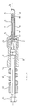
- the pinning clip for a set of sheets shown in FIG. 1, comprises a hollow body 1, closed at one of its ends by a drilled bottom 2.
- a rod 3 is secured to the bottom 2 and projects towards outside, on the side opposite to said body 1.
- a cap 4 covers the end of the body 1 near the bottom 2 and is made of a material which is not capable of marking said sheets. This cap 4 has a bearing face 5, covering said bottom 2.
- Said elastic blades 7 and 8 pass through the bottom 2 and the bearing face 5 and are arranged on either side of the rod 3. Thanks to the shape and the elasticity of said blades, the spouts 9 and 10 are spontaneously in contact with each other, when the rod 3 is not disposed between them.
- the threaded rod 6 is provided with an operating head 11.
- a nut 12 is mounted on the threaded rod 6.
- a helical spring 13 is mounted on the threaded rod 6, between the nut 12 and the body 1. The end of the spring 13, opposite the nut 12, is capable of bearing on the opposite end 14 of said body 1.
- a deformable protective tube 15 surrounds the rod 3 and the elastic blades 7 and 8, outside the body 1. At its end 16, opposite the body 1, the protective tube 15 is closed, in any desired manner. At its end close to the body 1, the protective tube 15 is provided with a collar 17, capable of being supported on the bearing face 5.
- the protective tube 15 is assumed to be free relative to the body 1.
- said protective tube 15 could be integral with said body 1, by example via the cap 4.
- the relative translational movement between the body 1 and the blades 7 and 8 has the consequence that the set of sheets 22, 23 and 24 is then pressed between the face d 'support 5 and the flange 17, on the one hand, and the local radial deformations 25 and 26, caused to the tube 15 by the radial spacing of the attachment nozzles 9 and 10. These therefore take support at the periphery of the hole 21 of the sheet 24, via the deformed part 25, 26 of the tube 15.
- the deformations 25 and 26 are permanent, even if the clip is returned to its relaxed state, by relative movement of rotation in opposite direction between the operating head 11 and the nut 12. This return to the relaxed state makes it possible to release the clip from the set of sheets 22, 23 and 24, the deformed tube 15 remaining however in place (FIG. 2a)
- the tube 15 is made of elastically deformable material, the deformations 25 and 26 disappear, as soon as the staple is relaxed (see FIG. 3a)
- the tube 15 can then be removed from the set of sheets 22,23, 24, simultaneously or after disassembly of the clip, depending on whether said tube is integral with it or not and may be reused after cleaning.
- the set of sheets 22, 23, 24 is then in the state shown in FIG. 3b.
- the burrs of product 27 can then be removed inside the holes 19, 20 and 21 and on the plates 22 and 24, for example by boring.
Landscapes
- Engineering & Computer Science (AREA)
- Mechanical Engineering (AREA)
- General Engineering & Computer Science (AREA)
- Insertion Pins And Rivets (AREA)
- Connection Of Plates (AREA)
- Clamps And Clips (AREA)
Applications Claiming Priority (2)
| Application Number | Priority Date | Filing Date | Title |
|---|---|---|---|
| FR8803221 | 1988-03-11 | ||
| FR8803221A FR2628489B1 (fr) | 1988-03-11 | 1988-03-11 | Agrafe d'epinglage a tube protecteur pour toles ou analogues |
Publications (2)
| Publication Number | Publication Date |
|---|---|
| EP0334706A1 true EP0334706A1 (de) | 1989-09-27 |
| EP0334706B1 EP0334706B1 (de) | 1991-05-29 |
Family
ID=9364201
Family Applications (1)
| Application Number | Title | Priority Date | Filing Date |
|---|---|---|---|
| EP89400660A Expired - Lifetime EP0334706B1 (de) | 1988-03-11 | 1989-03-09 | Einsteckbare Klammer mit Schutzhülse für Bleche oder ähnliches |
Country Status (7)
| Country | Link |
|---|---|
| US (1) | US4936726A (de) |
| EP (1) | EP0334706B1 (de) |
| JP (1) | JPH01283419A (de) |
| CA (1) | CA1310523C (de) |
| DE (1) | DE68900090D1 (de) |
| ES (1) | ES2022756B3 (de) |
| FR (1) | FR2628489B1 (de) |
Cited By (5)
| Publication number | Priority date | Publication date | Assignee | Title |
|---|---|---|---|---|
| EP0533561A1 (de) * | 1991-09-19 | 1993-03-24 | DASSAULT AVIATION Société anonyme dite: | Abnehmbare Vorrichtung zum Zusammenfügen von Unterteilen die mit einem Loch vorsehen sind |
| FR2720451A1 (fr) * | 1994-05-30 | 1995-12-01 | Valeo Systemes Dessuyage | Agencement pour le montage et la fixation d'un ensemble sur la caisse d'un véhicule automobile et module d'essuyage comportant un tel agencement. |
| EP1889688A1 (de) * | 2006-08-18 | 2008-02-20 | Fairchild Fasteners Europe - Camloc GmbH | Befestigungsanordnung und Einweghülse hierfür |
| FR2953260A1 (fr) * | 2009-11-27 | 2011-06-03 | Eurocopter France | Moyen de positionnement d'une premiere structure par rapport a une deuxieme structure, procede de positionnement et procede d'assemblage d'une premiere structure a une deuxieme structure |
| US10116257B2 (en) | 2009-08-14 | 2018-10-30 | Accurate Solar Power, Llc | Enhanced solar panels, liquid delivery systems and associated processes for solar energy systems |
Families Citing this family (24)
| Publication number | Priority date | Publication date | Assignee | Title |
|---|---|---|---|---|
| US5927919A (en) * | 1998-03-09 | 1999-07-27 | Mcdonnell Douglas Corporation | Spring loaded bushed wedgelock |
| DE60116399T2 (de) * | 2001-12-03 | 2006-09-07 | Nokia Corporation | Adressierung und leitweglenkung in einem drahtlosen maschennetzwerk |
| US6722711B2 (en) * | 2002-04-09 | 2004-04-20 | Roger S. Kitzis | Anti-animal container lock |
| US6755407B1 (en) * | 2003-02-04 | 2004-06-29 | The Boeing Company | Tool clamp and method |
| US6827345B2 (en) † | 2003-02-20 | 2004-12-07 | The Boeing Company | Wedge-lock fastener and associated installation and assembly methods |
| US7538465B2 (en) * | 2003-07-28 | 2009-05-26 | Delta Electronics, Inc. | Fan assembly and its housing |
| US7070375B2 (en) * | 2004-10-15 | 2006-07-04 | The Boeing Company | Clamping fastener grip length indicator |
| US8534651B2 (en) * | 2005-02-02 | 2013-09-17 | The Boeing Company | Hole-filling three-prong temporary fastener |
| US7246828B2 (en) * | 2005-08-02 | 2007-07-24 | Kitzis Roger S | Refined anti-animal container lock |
| FR2927675B1 (fr) * | 2008-02-19 | 2013-02-08 | Lisi Aerospace | Dispositif de fixation provisoire et reutilisable destine au pre-assemblage d'au moins deux elements structuraux prealablement perces. |
| RU2684249C1 (ru) * | 2013-11-19 | 2019-04-04 | Стэндерд Кар Трак Компани | Устройство закрепления транспортного средства железнодорожного вагона для перевозки автомобилей |
| GB2540576B (en) * | 2015-07-22 | 2017-08-23 | Kwikbolt Ltd | High tolerance removable blind fastener |
| US11224950B2 (en) | 2018-12-21 | 2022-01-18 | The Boeing Company | Method and apparatus for single-sided clamp-up |
| EP3677361A1 (de) * | 2018-12-21 | 2020-07-08 | The Boeing Company | Verfahren und vorrichtung zum einseitigen einspannen |
| US11224951B2 (en) | 2018-12-21 | 2022-01-18 | The Boeing Company | Method and apparatus for single-sided clamp-up |
| NL2022544B1 (en) * | 2019-02-08 | 2020-08-19 | Boeing Co | Method and apparatus for single-sided clamp-up |
| NL2022542B1 (en) * | 2019-02-08 | 2020-08-19 | Boeing Co | Method and apparatus for single-sided clamp-up |
| EP3670021A1 (de) * | 2018-12-21 | 2020-06-24 | The Boeing Company | Verfahren und vorrichtung zum einseitigen einspannen |
| US11884377B2 (en) | 2018-12-21 | 2024-01-30 | The Boeing Company | High-density robotic system |
| US11584503B2 (en) | 2018-12-21 | 2023-02-21 | The Boeing Company | High-density robotic system |
| NL2022545B1 (en) * | 2019-02-08 | 2020-08-19 | Boeing Co | Method and apparatus for single-sided clamp-up |
| US11305390B2 (en) | 2018-12-21 | 2022-04-19 | The Boeing Company | Method and apparatus for single-sided clamp-up |
| US11466719B2 (en) | 2019-12-20 | 2022-10-11 | Spirit Aerosystems, Inc. | Cap for temporary fastener |
| FR3106077B1 (fr) * | 2020-01-13 | 2022-04-01 | Lisi Aerospace | Agrafe d’épinglage à pince alignée |
Citations (3)
| Publication number | Priority date | Publication date | Assignee | Title |
|---|---|---|---|---|
| DE1678410U (de) * | 1954-03-29 | 1954-06-24 | Bruno Panknin | Verbindungsmittel benutzbarer duebel. |
| DE1829243U (de) * | 1959-12-08 | 1961-04-06 | Henschel Werke G M B H | Nietartiger verschlussstopfen. |
| GB1269953A (en) * | 1968-07-02 | 1972-04-12 | Bifurcated Engineering Ltd | Improvements relating to a method of and apparatus for rivetting |
Family Cites Families (12)
| Publication number | Priority date | Publication date | Assignee | Title |
|---|---|---|---|---|
| CA697654A (en) * | 1964-11-10 | Illinois Tool Works Inc. | Expandable fastener stud | |
| US1994210A (en) * | 1932-07-05 | 1935-03-12 | Chobert Jacques Franco Gabriel | Method of connecting hollow bodies |
| GB413403A (en) * | 1933-02-09 | 1934-07-19 | A T S Company Ltd | Improved clip for holding sheet metal together |
| US2562721A (en) * | 1941-08-13 | 1951-07-31 | United Air Lines Inc | Method of hydraulically expanding hollow rivets |
| FR1269629A (fr) * | 1959-07-31 | 1961-08-18 | Tinnerman Products Inc | Nouveau dispositif de fixation |
| JPS5630740Y2 (de) * | 1976-08-16 | 1981-07-22 | ||
| JPS60115749A (ja) * | 1983-11-29 | 1985-06-22 | まるとく産業株式会社 | エキスパンシヨンジヨイント |
| JPS60141309U (ja) * | 1984-02-28 | 1985-09-19 | ド−エイ外装有限会社 | 目地カバ− |
| US4548533A (en) * | 1984-04-20 | 1985-10-22 | Monogram Industries, Inc. | Wedge-type fastener |
| SU1244403A2 (ru) * | 1985-02-27 | 1986-07-15 | Предприятие П/Я Р-6601 | Резьбовое соединение с односторонним доступом |
| JPS6227911U (de) * | 1985-08-03 | 1987-02-20 | ||
| US4767248A (en) * | 1986-03-18 | 1988-08-30 | Monogram Industries, Inc. | Fastener for securing panels of composite materials |
-
1988
- 1988-03-11 FR FR8803221A patent/FR2628489B1/fr not_active Expired - Fee Related
-
1989
- 1989-03-09 DE DE8989400660T patent/DE68900090D1/de not_active Expired - Fee Related
- 1989-03-09 EP EP89400660A patent/EP0334706B1/de not_active Expired - Lifetime
- 1989-03-09 ES ES89400660T patent/ES2022756B3/es not_active Expired - Lifetime
- 1989-03-10 CA CA000593371A patent/CA1310523C/fr not_active Expired - Fee Related
- 1989-03-10 JP JP1056561A patent/JPH01283419A/ja active Pending
- 1989-03-10 US US07/321,776 patent/US4936726A/en not_active Expired - Fee Related
Patent Citations (3)
| Publication number | Priority date | Publication date | Assignee | Title |
|---|---|---|---|---|
| DE1678410U (de) * | 1954-03-29 | 1954-06-24 | Bruno Panknin | Verbindungsmittel benutzbarer duebel. |
| DE1829243U (de) * | 1959-12-08 | 1961-04-06 | Henschel Werke G M B H | Nietartiger verschlussstopfen. |
| GB1269953A (en) * | 1968-07-02 | 1972-04-12 | Bifurcated Engineering Ltd | Improvements relating to a method of and apparatus for rivetting |
Cited By (8)
| Publication number | Priority date | Publication date | Assignee | Title |
|---|---|---|---|---|
| EP0533561A1 (de) * | 1991-09-19 | 1993-03-24 | DASSAULT AVIATION Société anonyme dite: | Abnehmbare Vorrichtung zum Zusammenfügen von Unterteilen die mit einem Loch vorsehen sind |
| FR2681541A1 (fr) * | 1991-09-19 | 1993-03-26 | Dassault Aviat | Dispositif amovible d'assemblage de pieces presentant chacune un trou. |
| FR2720451A1 (fr) * | 1994-05-30 | 1995-12-01 | Valeo Systemes Dessuyage | Agencement pour le montage et la fixation d'un ensemble sur la caisse d'un véhicule automobile et module d'essuyage comportant un tel agencement. |
| EP0685657A1 (de) * | 1994-05-30 | 1995-12-06 | Valeo Systemes D'essuyage | Anordnung zur Montage bzw. Befestigung eines Aggregats an einem Wagenkasten, sowie Wischanlage mit einer derartigen Anordnung |
| EP1889688A1 (de) * | 2006-08-18 | 2008-02-20 | Fairchild Fasteners Europe - Camloc GmbH | Befestigungsanordnung und Einweghülse hierfür |
| US8033003B2 (en) | 2006-08-18 | 2011-10-11 | Fairchild Fasteners Europe | Fastening assembly and disposable sleeve for same |
| US10116257B2 (en) | 2009-08-14 | 2018-10-30 | Accurate Solar Power, Llc | Enhanced solar panels, liquid delivery systems and associated processes for solar energy systems |
| FR2953260A1 (fr) * | 2009-11-27 | 2011-06-03 | Eurocopter France | Moyen de positionnement d'une premiere structure par rapport a une deuxieme structure, procede de positionnement et procede d'assemblage d'une premiere structure a une deuxieme structure |
Also Published As
| Publication number | Publication date |
|---|---|
| CA1310523C (fr) | 1992-11-24 |
| FR2628489A1 (fr) | 1989-09-15 |
| JPH01283419A (ja) | 1989-11-15 |
| DE68900090D1 (de) | 1991-07-04 |
| EP0334706B1 (de) | 1991-05-29 |
| ES2022756B3 (es) | 1991-12-01 |
| US4936726A (en) | 1990-06-26 |
| FR2628489B1 (fr) | 1990-12-28 |
Similar Documents
| Publication | Publication Date | Title |
|---|---|---|
| EP0334706B1 (de) | Einsteckbare Klammer mit Schutzhülse für Bleche oder ähnliches | |
| CA1322204C (fr) | Agrafe d'epinglage a mecanisme interieur | |
| FR2489446A1 (fr) | Attache aveugle avec moyen de serrage deformable | |
| FR2524095A1 (fr) | Manchon elastique destine a etre monte sur une broche support d'un frein a etrier | |
| BE898126A (fr) | Pince à dénuder pour extrémités de conducteurs. | |
| FR2657925A1 (fr) | Dispositif de fixation sur panneau de type sandwich. | |
| EP0016669A1 (de) | Montagemuffe zum Befestigen einer Schraube in einem Gegenstand, insbesondere aus weichem Material | |
| FR2650866A1 (fr) | Cage a rotule pour articulation demontable | |
| EP0325069B1 (de) | Befestigungsmutter | |
| EP3261803B1 (de) | Nietvorrichtung für präzisionsanordnung | |
| EP0325642B1 (de) | Punktbefestigungsvorrichtung von elementen mit einem rand, insbesondere von platten auf einer tragkonstruktion | |
| FR2493939A1 (fr) | Frein a disque | |
| EP2112416A1 (de) | Steckanschluss für mindestens ein Rohr | |
| FR2610386A1 (fr) | Dispositif d'etancheite pour un assemblage piece/tube | |
| FR2835576A1 (fr) | Element de fixation | |
| EP1464260A1 (de) | Fensteranordnung mit einer Gardinenstange | |
| EP0394127B1 (de) | Expandierbarer Ring für dichte Befestigung einer Schutzmanschette in einer Öffnung | |
| BE1007798A6 (fr) | Couvre-joint pour revetement de sol et procede pour sa mise en oeuvre. | |
| EP1914437A1 (de) | Scheibenbremse mit rückstellendem Dämpfungsblech | |
| EP1760332B1 (de) | Ein Gegenstand, der mittels eines Gasdruckwerkzeugs auf eine Unterlage befestigt wird | |
| CH619757A5 (en) | Rivet | |
| CH638874A5 (fr) | Appareil pour la pose d'un dispositif d'attache. | |
| FR3137597A1 (fr) | Systèmes et guides de perçage pour rivet | |
| WO1996018841A2 (fr) | Collier de serrage d'une piece tubulaire | |
| FR2548295A1 (fr) | Rivet aveugle |
Legal Events
| Date | Code | Title | Description |
|---|---|---|---|
| PUAI | Public reference made under article 153(3) epc to a published international application that has entered the european phase |
Free format text: ORIGINAL CODE: 0009012 |
|
| AK | Designated contracting states |
Kind code of ref document: A1 Designated state(s): DE ES GB IT NL |
|
| 17P | Request for examination filed |
Effective date: 19891013 |
|
| 17Q | First examination report despatched |
Effective date: 19900605 |
|
| GRAA | (expected) grant |
Free format text: ORIGINAL CODE: 0009210 |
|
| AK | Designated contracting states |
Kind code of ref document: B1 Designated state(s): DE ES GB IT NL |
|
| GBT | Gb: translation of ep patent filed (gb section 77(6)(a)/1977) | ||
| REF | Corresponds to: |
Ref document number: 68900090 Country of ref document: DE Date of ref document: 19910704 |
|
| ITF | It: translation for a ep patent filed | ||
| PGFP | Annual fee paid to national office [announced via postgrant information from national office to epo] |
Ref country code: ES Payment date: 19920316 Year of fee payment: 4 |
|
| PGFP | Annual fee paid to national office [announced via postgrant information from national office to epo] |
Ref country code: DE Payment date: 19920324 Year of fee payment: 4 |
|
| PGFP | Annual fee paid to national office [announced via postgrant information from national office to epo] |
Ref country code: NL Payment date: 19920331 Year of fee payment: 4 |
|
| PLBE | No opposition filed within time limit |
Free format text: ORIGINAL CODE: 0009261 |
|
| STAA | Information on the status of an ep patent application or granted ep patent |
Free format text: STATUS: NO OPPOSITION FILED WITHIN TIME LIMIT |
|
| 26N | No opposition filed | ||
| PG25 | Lapsed in a contracting state [announced via postgrant information from national office to epo] |
Ref country code: GB Effective date: 19930309 |
|
| PG25 | Lapsed in a contracting state [announced via postgrant information from national office to epo] |
Ref country code: ES Free format text: LAPSE BECAUSE OF NON-PAYMENT OF DUE FEES Effective date: 19930310 |
|
| PG25 | Lapsed in a contracting state [announced via postgrant information from national office to epo] |
Ref country code: NL Effective date: 19931001 |
|
| GBPC | Gb: european patent ceased through non-payment of renewal fee |
Effective date: 19930309 |
|
| NLV4 | Nl: lapsed or anulled due to non-payment of the annual fee | ||
| PG25 | Lapsed in a contracting state [announced via postgrant information from national office to epo] |
Ref country code: DE Effective date: 19931201 |
|
| REG | Reference to a national code |
Ref country code: ES Ref legal event code: FD2A Effective date: 19990301 |
|
| PG25 | Lapsed in a contracting state [announced via postgrant information from national office to epo] |
Ref country code: IT Free format text: LAPSE BECAUSE OF NON-PAYMENT OF DUE FEES;WARNING: LAPSES OF ITALIAN PATENTS WITH EFFECTIVE DATE BEFORE 2007 MAY HAVE OCCURRED AT ANY TIME BEFORE 2007. THE CORRECT EFFECTIVE DATE MAY BE DIFFERENT FROM THE ONE RECORDED. Effective date: 20050309 |