EP0334817A1 - Radiateur pour véhicules motorisés - Google Patents
Radiateur pour véhicules motorisés Download PDFInfo
- Publication number
- EP0334817A1 EP0334817A1 EP89830099A EP89830099A EP0334817A1 EP 0334817 A1 EP0334817 A1 EP 0334817A1 EP 89830099 A EP89830099 A EP 89830099A EP 89830099 A EP89830099 A EP 89830099A EP 0334817 A1 EP0334817 A1 EP 0334817A1
- Authority
- EP
- European Patent Office
- Prior art keywords
- gasket
- end plate
- tubes
- holes
- cover
- Prior art date
- Legal status (The legal status is an assumption and is not a legal conclusion. Google has not performed a legal analysis and makes no representation as to the accuracy of the status listed.)
- Withdrawn
Links
Images
Classifications
-
- F—MECHANICAL ENGINEERING; LIGHTING; HEATING; WEAPONS; BLASTING
- F28—HEAT EXCHANGE IN GENERAL
- F28F—DETAILS OF HEAT-EXCHANGE AND HEAT-TRANSFER APPARATUS, OF GENERAL APPLICATION
- F28F21/00—Constructions of heat-exchange apparatus characterised by the selection of particular materials
- F28F21/06—Constructions of heat-exchange apparatus characterised by the selection of particular materials of plastics material
- F28F21/067—Details
-
- F—MECHANICAL ENGINEERING; LIGHTING; HEATING; WEAPONS; BLASTING
- F16—ENGINEERING ELEMENTS AND UNITS; GENERAL MEASURES FOR PRODUCING AND MAINTAINING EFFECTIVE FUNCTIONING OF MACHINES OR INSTALLATIONS; THERMAL INSULATION IN GENERAL
- F16L—PIPES; JOINTS OR FITTINGS FOR PIPES; SUPPORTS FOR PIPES, CABLES OR PROTECTIVE TUBING; MEANS FOR THERMAL INSULATION IN GENERAL
- F16L41/00—Branching pipes; Joining pipes to walls
- F16L41/001—Branching pipes; Joining pipes to walls the wall being a pipe plate
-
- F—MECHANICAL ENGINEERING; LIGHTING; HEATING; WEAPONS; BLASTING
- F28—HEAT EXCHANGE IN GENERAL
- F28F—DETAILS OF HEAT-EXCHANGE AND HEAT-TRANSFER APPARATUS, OF GENERAL APPLICATION
- F28F9/00—Casings; Header boxes; Auxiliary supports for elements; Auxiliary members within casings
- F28F9/02—Header boxes; End plates
- F28F9/0219—Arrangements for sealing end plates into casing or header box; Header box sub-elements
- F28F9/0224—Header boxes formed by sealing end plates into covers
- F28F9/0226—Header boxes formed by sealing end plates into covers with resilient gaskets
-
- F—MECHANICAL ENGINEERING; LIGHTING; HEATING; WEAPONS; BLASTING
- F28—HEAT EXCHANGE IN GENERAL
- F28F—DETAILS OF HEAT-EXCHANGE AND HEAT-TRANSFER APPARATUS, OF GENERAL APPLICATION
- F28F9/00—Casings; Header boxes; Auxiliary supports for elements; Auxiliary members within casings
- F28F9/02—Header boxes; End plates
- F28F9/04—Arrangements for sealing elements into header boxes or end plates
- F28F9/06—Arrangements for sealing elements into header boxes or end plates by dismountable joints
- F28F9/14—Arrangements for sealing elements into header boxes or end plates by dismountable joints by force-joining
Definitions
- the present invention relates to a heat exchanger, particularly for motor vehicle air-conditioning systems, of the type comprising a plurality of tubes, at least one end plate having a plurality of holes provided with collars in which the ends of the tubes are engaged, a cover fixed to the end plate so as to define a header chamber, gasket having a plurality of holes provided with thickened edges, the thickened edges being interposed between the tubes and the collars of the end plate, and a gasket-pressing plate situated on the side of the gasket which faces the header chamber and also having a plurality of holes in which the ends of the tubes of the exchanger are housed.
- the object of the present invention is to provide a heat exchanger which can be assembled quickly and easily and enables a seal to be effected between the tubes and the header, which does not depend on the sectional shapes of the tubes.
- this object is achieved by virtue of the fact that the cover has engagement means which, when the cover is fitted to the end plate, are adapted to cooperate with the gasket-pressing plate so as to compress it and thus press the thickened edges of the holes of the gasket against the outer surfaces of the tubes to effect a seal between the tubes and the end plate.
- tubes having circular, oval or elliptical sections can be used in a heat exchanger according to the invention.
- the cover and the end plate are preferably fitted together by vibration, ultrasonic or hot-blade face welding.
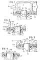
- a tube of a heat exchanger used, for example, in a motor vehicle air-conditioning system is indicated 10 and is mounted in a corresponding hole 12 in a plastics end plate 14.
- the end plate 14 has substantially frusto-conical collars 14a whose function will become clear from the following description.
- the tubes 10 are brought into the holes 12 so as to ensure that the joint has a predetermined mechanical strength.
- a cover 16 is joined to the end plate 14 by ultrasonic, vibration or hot-blade welding and defines a header chamber A divided by a vertical wall 18. If the header chamber A is not to be divided, rods may be used instead of the wall 18 to stiffen the header.
- the cover 16 has a side wall 16a which, in correspondence with an internal face, is provided with an annular shoulder 20 for cooperating with a peripheral edge 22a of a gasket-pressing plate 22 provided with holes 23 in which the ends 10a of the tubes 10 are housed.
- a gasket 24 of elastomeric material is interposed between the gasket-pressing plate 22 and the end plate 14 and is provided with holes 26 in correspondence with the ends 10a of the tubes 10.
- the gasket 24 has thickened edges 24a in correspondence with the holes 26.
- these thickened edges 24a are pressed into the space between the collar 14a and the respective tube 10 by means of the gasket-pressing plate 22 which is pushed by the annular shoulder 20 and by the wall 18.
- the deformation of the edge 24a therefore ensures a seal between the tube and the header, as well as "mechanical" fixing between the tube and the header.
- the frusto-conical collars may be formed at the edges 22b of the gasket-pressing plate 22 around the holes 23 ( Figure 4), instead of in the end plate.
- Figure 2 shows a second embodiment of the invention.
- the same reference numerals as in Figure 1 have been used for details which are substantially identical, whilst the same reference numerals as in Figure 1, but increased by 100, have been used for details which are similar.
- the end plate 114 has collars 114a with L-shaped sections so as to define an annular chamber B beside the end 10a of the tube 10.
- the gasket-pressing plate 122 has tubular portions 30 projecting from the plane of the plate so as to slide substantially telescopically relative to the collar 114a and compress the thickened edges 124a of the gasket 124. The deformation of the gasket is thus more easily controllable.
- the pressure between the gasket-pressing plate 222 and the end plate 214 is achieved by virtue of the engagement of pins 32 formed integrally with the plate 214 in corresponding auxiliary holes 34 formed in the gasket-pressing plate 222.
- the cooperation between the plate 222 and the pins 32 is achieved, for example, by upsetting the free ends 34a of the pins 34; if the end plate 214 is made of plastics, the ends 34a can be subjected to plastic deformation, for example, by means of ultrasound.
- the deformation of the thickened edges 224a of the gasket 224 is thus achieved independently of the fitting together of the cover 16 and the end plate 214.
Landscapes
- Engineering & Computer Science (AREA)
- General Engineering & Computer Science (AREA)
- Mechanical Engineering (AREA)
- Physics & Mathematics (AREA)
- Thermal Sciences (AREA)
- Lining Or Joining Of Plastics Or The Like (AREA)
Applications Claiming Priority (2)
| Application Number | Priority Date | Filing Date | Title |
|---|---|---|---|
| IT6726388 | 1988-03-24 | ||
| IT67263/88A IT1219145B (it) | 1988-03-24 | 1988-03-24 | Radiatore per autoveicoli |
Publications (1)
| Publication Number | Publication Date |
|---|---|
| EP0334817A1 true EP0334817A1 (fr) | 1989-09-27 |
Family
ID=11300960
Family Applications (1)
| Application Number | Title | Priority Date | Filing Date |
|---|---|---|---|
| EP89830099A Withdrawn EP0334817A1 (fr) | 1988-03-24 | 1989-03-07 | Radiateur pour véhicules motorisés |
Country Status (2)
| Country | Link |
|---|---|
| EP (1) | EP0334817A1 (fr) |
| IT (1) | IT1219145B (fr) |
Cited By (9)
| Publication number | Priority date | Publication date | Assignee | Title |
|---|---|---|---|---|
| DE4041671A1 (de) * | 1990-12-22 | 1992-06-25 | Behr Gmbh & Co | Waermetauscher |
| EP0736717A1 (fr) * | 1995-04-07 | 1996-10-09 | Regie Nationale Des Usines Renault S.A. | Dispositif de raccordement étanche pour circuit hydraulique |
| FR2783907A1 (fr) * | 1998-09-25 | 2000-03-31 | Valeo Thermique Moteur Sa | Echangeur de chaleur d'encombrement reduit, en particulier pour vehicule automobile |
| FR2803378A1 (fr) * | 1999-12-29 | 2001-07-06 | Valeo Climatisation | Echangeur de chaleur a tubes a plusieurs canaux, en particulier pour vehicule automobile |
| EP1273864A3 (fr) * | 2001-07-05 | 2003-06-11 | Modine Manufacturing Company | Echangeur de chaleur |
| WO2013076567A3 (fr) * | 2011-11-25 | 2015-02-19 | Pilosio Bruno | Échangeur de chaleur perfectionné et son procédé de production |
| CN105202963A (zh) * | 2015-09-29 | 2015-12-30 | 茂名重力石化机械制造有限公司 | 一种换热管与管板的非焊接强制性密封结构 |
| KR20160145137A (ko) * | 2014-05-05 | 2016-12-19 | 발레오 시스템므 떼르미끄 | 자동차의 열교환기를 위한 헤더 |
| CN111998718A (zh) * | 2020-09-10 | 2020-11-27 | 张春丽 | 一种换热器的双管板密封装置 |
Citations (7)
| Publication number | Priority date | Publication date | Assignee | Title |
|---|---|---|---|---|
| GB315934A (en) * | 1928-05-05 | 1929-07-25 | Henry Kirk | Improvements in and connected with tube radiators |
| GB431863A (en) * | 1934-01-15 | 1935-07-15 | Herbert Houlding | Improvements in or relating to radiators and like tubes, and in joints therefor |
| GB559981A (en) * | 1942-10-22 | 1944-03-14 | James Chew And Company Ltd | Improvements relating to tube joints |
| DE2004860A1 (de) * | 1969-02-03 | 1970-08-06 | S.A. des Usines Chausson, Asnieres, Seine (Frankreich) | Wärmetauscher zum Erhitzen oder Kühlen eines Strömungsmittels, insbesondere für Fahrzeuge |
| FR2214875A1 (fr) * | 1973-01-20 | 1974-08-19 | Sueddeutsche Kuehler Behr | |
| DE2930577A1 (de) * | 1979-07-27 | 1981-02-12 | Wiessner Gmbh | Waermetauscher |
| FR2512941A1 (fr) * | 1981-09-14 | 1983-03-18 | Valeo | Echangeur de chaleur a faisceau de tubes paralleles et procede d'assemblage de ses elements constitutifs |
-
1988
- 1988-03-24 IT IT67263/88A patent/IT1219145B/it active
-
1989
- 1989-03-07 EP EP89830099A patent/EP0334817A1/fr not_active Withdrawn
Patent Citations (7)
| Publication number | Priority date | Publication date | Assignee | Title |
|---|---|---|---|---|
| GB315934A (en) * | 1928-05-05 | 1929-07-25 | Henry Kirk | Improvements in and connected with tube radiators |
| GB431863A (en) * | 1934-01-15 | 1935-07-15 | Herbert Houlding | Improvements in or relating to radiators and like tubes, and in joints therefor |
| GB559981A (en) * | 1942-10-22 | 1944-03-14 | James Chew And Company Ltd | Improvements relating to tube joints |
| DE2004860A1 (de) * | 1969-02-03 | 1970-08-06 | S.A. des Usines Chausson, Asnieres, Seine (Frankreich) | Wärmetauscher zum Erhitzen oder Kühlen eines Strömungsmittels, insbesondere für Fahrzeuge |
| FR2214875A1 (fr) * | 1973-01-20 | 1974-08-19 | Sueddeutsche Kuehler Behr | |
| DE2930577A1 (de) * | 1979-07-27 | 1981-02-12 | Wiessner Gmbh | Waermetauscher |
| FR2512941A1 (fr) * | 1981-09-14 | 1983-03-18 | Valeo | Echangeur de chaleur a faisceau de tubes paralleles et procede d'assemblage de ses elements constitutifs |
Cited By (18)
| Publication number | Priority date | Publication date | Assignee | Title |
|---|---|---|---|---|
| DE4041671A1 (de) * | 1990-12-22 | 1992-06-25 | Behr Gmbh & Co | Waermetauscher |
| EP0736717A1 (fr) * | 1995-04-07 | 1996-10-09 | Regie Nationale Des Usines Renault S.A. | Dispositif de raccordement étanche pour circuit hydraulique |
| FR2732744A1 (fr) * | 1995-04-07 | 1996-10-11 | Renault | Dispositif de raccordement etanche pour circuit hydraulique |
| FR2783907A1 (fr) * | 1998-09-25 | 2000-03-31 | Valeo Thermique Moteur Sa | Echangeur de chaleur d'encombrement reduit, en particulier pour vehicule automobile |
| WO2000019163A1 (fr) * | 1998-09-25 | 2000-04-06 | Valeo Thermique Moteur | Enchangeur de chaleur d'encombrement reduit, en particulier pour vehicule automobile |
| US6296051B1 (en) | 1998-09-25 | 2001-10-02 | Valeo Termique Moteur | Heat exchanger with reduced space requirement, in particular for motor vehicle |
| JP4869530B2 (ja) * | 1999-12-29 | 2012-02-08 | ヴァレオ クリマチザション | 熱交換器 |
| FR2803378A1 (fr) * | 1999-12-29 | 2001-07-06 | Valeo Climatisation | Echangeur de chaleur a tubes a plusieurs canaux, en particulier pour vehicule automobile |
| WO2001050080A3 (fr) * | 1999-12-29 | 2002-01-31 | Valeo Climatisation | Echangeur de chaleur a tubes a plusieurs canaux |
| JP2003519356A (ja) * | 1999-12-29 | 2003-06-17 | ヴァレオ クリマチザション | 熱交換器 |
| EP1273864A3 (fr) * | 2001-07-05 | 2003-06-11 | Modine Manufacturing Company | Echangeur de chaleur |
| WO2013076567A3 (fr) * | 2011-11-25 | 2015-02-19 | Pilosio Bruno | Échangeur de chaleur perfectionné et son procédé de production |
| KR20160145137A (ko) * | 2014-05-05 | 2016-12-19 | 발레오 시스템므 떼르미끄 | 자동차의 열교환기를 위한 헤더 |
| JP2017515086A (ja) * | 2014-05-05 | 2017-06-08 | ヴァレオ システム テルミク | 自動車の熱交換器用ヘッダ |
| US10180290B2 (en) | 2014-05-05 | 2019-01-15 | Valeo Systemes Thermiques | Header for a heat exchanger of a motor vehicle |
| CN105202963A (zh) * | 2015-09-29 | 2015-12-30 | 茂名重力石化机械制造有限公司 | 一种换热管与管板的非焊接强制性密封结构 |
| CN105202963B (zh) * | 2015-09-29 | 2017-12-08 | 茂名重力石化装备股份公司 | 一种换热管与管板的非焊接强制性密封结构 |
| CN111998718A (zh) * | 2020-09-10 | 2020-11-27 | 张春丽 | 一种换热器的双管板密封装置 |
Also Published As
| Publication number | Publication date |
|---|---|
| IT8867263A0 (it) | 1988-03-24 |
| IT1219145B (it) | 1990-05-03 |
Similar Documents
| Publication | Publication Date | Title |
|---|---|---|
| SU1223830A3 (ru) | Металлическа труба дл теплообменника и способ ее изготовлени | |
| US5660419A (en) | Connecting member for exhaust pipe | |
| US4125280A (en) | Multitube heat exchanger | |
| US3931834A (en) | Expansion tank diaphragm assembly | |
| US5314021A (en) | Heat exchanger with a plurality of ranges of tubes, in particular for a motor vehicle | |
| US4534407A (en) | Heat exchangers | |
| US4233726A (en) | Method of joining a tube to a plate | |
| US6851468B2 (en) | Heat exchanger | |
| JP3316692B2 (ja) | 自動車用に適する管束付熱交換器 | |
| US5348082A (en) | Heat exchanger with tubes of oblong cross section, in particular for motor vehicles | |
| US3035614A (en) | Expansion tank | |
| EP0724128B1 (fr) | Procédé pour la fabrication d'un échangeur de chaleur | |
| JPH0660711B2 (ja) | 押し潰すことができる封止領域およびバンドクランプを備えた管重ね継手 | |
| US5233756A (en) | Method of making a heat exchanger having a tubular manifold with transverse baffles | |
| MXPA96005319A (en) | Heat exchanger with sectionally pipe or oblonga and mont procedure | |
| KR970062642A (ko) | 자동차용의 납땜된 헤더를 구비한 열교환기 | |
| US4600051A (en) | Tank-header plate connection | |
| US4324290A (en) | Heat exchanger comprising a core of tubes engaged inside end plates mechanically connected with header boxes | |
| US4625793A (en) | Header for a heat exchanger | |
| US6644385B2 (en) | Heat exchanger with improved sealing gasket, for a motor vehicle in particular | |
| EP3290848B1 (fr) | Collecteur pour un échangeur de chaleur et son procédé de fabrication | |
| JPS6115095A (ja) | タンクと管寄せ板との結合装置 | |
| US20150184778A1 (en) | Pipe Component and Method for Manufacturing a Pipe Component | |
| JPH1018844A (ja) | 熱交換器用ヘッダープレート | |
| GB1590032A (en) | Heat exchangers |
Legal Events
| Date | Code | Title | Description |
|---|---|---|---|
| PUAI | Public reference made under article 153(3) epc to a published international application that has entered the european phase |
Free format text: ORIGINAL CODE: 0009012 |
|
| AK | Designated contracting states |
Kind code of ref document: A1 Designated state(s): DE ES FR GB IT SE |
|
| 17P | Request for examination filed |
Effective date: 19900317 |
|
| 17Q | First examination report despatched |
Effective date: 19910131 |
|
| STAA | Information on the status of an ep patent application or granted ep patent |
Free format text: STATUS: THE APPLICATION IS DEEMED TO BE WITHDRAWN |
|
| 18D | Application deemed to be withdrawn |
Effective date: 19910813 |