EP0334832A1 - Dispositif pour appliquer des moyens d'écartement - Google Patents
Dispositif pour appliquer des moyens d'écartement Download PDFInfo
- Publication number
- EP0334832A1 EP0334832A1 EP89890019A EP89890019A EP0334832A1 EP 0334832 A1 EP0334832 A1 EP 0334832A1 EP 89890019 A EP89890019 A EP 89890019A EP 89890019 A EP89890019 A EP 89890019A EP 0334832 A1 EP0334832 A1 EP 0334832A1
- Authority
- EP
- European Patent Office
- Prior art keywords
- strip
- roller
- suction head
- hollow cylinder
- cutting device
- Prior art date
- Legal status (The legal status is an assumption and is not a legal conclusion. Google has not performed a legal analysis and makes no representation as to the accuracy of the status listed.)
- Granted
Links
- 125000006850 spacer group Chemical group 0.000 title claims abstract description 38
- 239000011521 glass Substances 0.000 claims abstract description 60
- 238000005520 cutting process Methods 0.000 claims abstract description 26
- 239000007799 cork Substances 0.000 claims abstract description 9
- 230000001681 protective effect Effects 0.000 claims abstract description 7
- 239000012790 adhesive layer Substances 0.000 claims abstract description 4
- 238000004519 manufacturing process Methods 0.000 claims description 11
- 238000003825 pressing Methods 0.000 claims description 4
- 238000007789 sealing Methods 0.000 claims description 3
- 230000037431 insertion Effects 0.000 claims 1
- 238000003780 insertion Methods 0.000 claims 1
- 239000011888 foil Substances 0.000 abstract 1
- 238000000034 method Methods 0.000 description 4
- 230000000694 effects Effects 0.000 description 2
- 239000002184 metal Substances 0.000 description 2
- 239000004033 plastic Substances 0.000 description 2
- 238000004804 winding Methods 0.000 description 2
- 241001136792 Alle Species 0.000 description 1
- 238000001816 cooling Methods 0.000 description 1
- 230000001419 dependent effect Effects 0.000 description 1
- 235000012054 meals Nutrition 0.000 description 1
- 239000007921 spray Substances 0.000 description 1
- 229920001169 thermoplastic Polymers 0.000 description 1
- 239000004416 thermosoftening plastic Substances 0.000 description 1
Images

Classifications
-
- E—FIXED CONSTRUCTIONS
- E06—DOORS, WINDOWS, SHUTTERS, OR ROLLER BLINDS IN GENERAL; LADDERS
- E06B—FIXED OR MOVABLE CLOSURES FOR OPENINGS IN BUILDINGS, VEHICLES, FENCES OR LIKE ENCLOSURES IN GENERAL, e.g. DOORS, WINDOWS, BLINDS, GATES
- E06B3/00—Window sashes, door leaves, or like elements for closing wall or like openings; Layout of fixed or moving closures, e.g. windows in wall or like openings; Features of rigidly-mounted outer frames relating to the mounting of wing frames
- E06B3/66—Units comprising two or more parallel glass or like panes permanently secured together
- E06B3/673—Assembling the units
-
- B—PERFORMING OPERATIONS; TRANSPORTING
- B65—CONVEYING; PACKING; STORING; HANDLING THIN OR FILAMENTARY MATERIAL
- B65G—TRANSPORT OR STORAGE DEVICES, e.g. CONVEYORS FOR LOADING OR TIPPING, SHOP CONVEYOR SYSTEMS OR PNEUMATIC TUBE CONVEYORS
- B65G49/00—Conveying systems characterised by their application for specified purposes not otherwise provided for
- B65G49/05—Conveying systems characterised by their application for specified purposes not otherwise provided for for fragile or damageable materials or articles
- B65G49/06—Conveying systems characterised by their application for specified purposes not otherwise provided for for fragile or damageable materials or articles for fragile sheets, e.g. glass
- B65G49/068—Stacking or destacking devices; Means for preventing damage to stacked sheets, e.g. spaces
- B65G49/069—Means for avoiding damage to stacked plate glass, e.g. by interposing paper or powder spacers in the stack
-
- B—PERFORMING OPERATIONS; TRANSPORTING
- B65—CONVEYING; PACKING; STORING; HANDLING THIN OR FILAMENTARY MATERIAL
- B65G—TRANSPORT OR STORAGE DEVICES, e.g. CONVEYORS FOR LOADING OR TIPPING, SHOP CONVEYOR SYSTEMS OR PNEUMATIC TUBE CONVEYORS
- B65G2249/00—Aspects relating to conveying systems for the manufacture of fragile sheets
- B65G2249/04—Arrangements of vacuum systems or suction cups
-
- Y—GENERAL TAGGING OF NEW TECHNOLOGICAL DEVELOPMENTS; GENERAL TAGGING OF CROSS-SECTIONAL TECHNOLOGIES SPANNING OVER SEVERAL SECTIONS OF THE IPC; TECHNICAL SUBJECTS COVERED BY FORMER USPC CROSS-REFERENCE ART COLLECTIONS [XRACs] AND DIGESTS
- Y10—TECHNICAL SUBJECTS COVERED BY FORMER USPC
- Y10T—TECHNICAL SUBJECTS COVERED BY FORMER US CLASSIFICATION
- Y10T156/00—Adhesive bonding and miscellaneous chemical manufacture
- Y10T156/12—Surface bonding means and/or assembly means with cutting, punching, piercing, severing or tearing
- Y10T156/1317—Means feeding plural workpieces to be joined
- Y10T156/1322—Severing before bonding or assembling of parts
-
- Y—GENERAL TAGGING OF NEW TECHNOLOGICAL DEVELOPMENTS; GENERAL TAGGING OF CROSS-SECTIONAL TECHNOLOGIES SPANNING OVER SEVERAL SECTIONS OF THE IPC; TECHNICAL SUBJECTS COVERED BY FORMER USPC CROSS-REFERENCE ART COLLECTIONS [XRACs] AND DIGESTS
- Y10—TECHNICAL SUBJECTS COVERED BY FORMER USPC
- Y10T—TECHNICAL SUBJECTS COVERED BY FORMER US CLASSIFICATION
- Y10T156/00—Adhesive bonding and miscellaneous chemical manufacture
- Y10T156/12—Surface bonding means and/or assembly means with cutting, punching, piercing, severing or tearing
- Y10T156/1317—Means feeding plural workpieces to be joined
- Y10T156/1322—Severing before bonding or assembling of parts
- Y10T156/1339—Delivering cut part in sequence to serially conveyed articles
-
- Y—GENERAL TAGGING OF NEW TECHNOLOGICAL DEVELOPMENTS; GENERAL TAGGING OF CROSS-SECTIONAL TECHNOLOGIES SPANNING OVER SEVERAL SECTIONS OF THE IPC; TECHNICAL SUBJECTS COVERED BY FORMER USPC CROSS-REFERENCE ART COLLECTIONS [XRACs] AND DIGESTS
- Y10—TECHNICAL SUBJECTS COVERED BY FORMER USPC
- Y10T—TECHNICAL SUBJECTS COVERED BY FORMER US CLASSIFICATION
- Y10T156/00—Adhesive bonding and miscellaneous chemical manufacture
- Y10T156/17—Surface bonding means and/or assemblymeans with work feeding or handling means
- Y10T156/1702—For plural parts or plural areas of single part
- Y10T156/1744—Means bringing discrete articles into assembled relationship
Definitions
- the invention relates to a device for attaching spacer plates on glass panes, in particular on insulating glass panes.
- Insulating glass panes are placed on trestles after their manufacture, the procedure being that initially insulating glass panes with larger dimensions are placed in front of which insulating glass panes with increasingly smaller dimensions are then placed.
- cork plates usually square cork plates, are glued by hand to the rear glass panes of the insulating glass panes. These cork plates must be attached to the back of the glass panes of the insulating glass panes, i.e.
- lifting devices which are equipped, for example, with suction heads, act on the front sides in order to lift the insulating glass panes off the production line and on turn off the bearing blocks.
- the invention has for its object to provide a device with which the attachment of spacer plates can be carried out without the need for manual activities.
- this object is achieved with a device for attaching spacer plates on glass panes, in particular glass panes of insulating glass panes, which is characterized by a supply spool for a strip of cork or the like, which is covered on one side with an adhesive layer which is covered by a protective film , by a drive for conveying the strip to a cutting device, by a pressing device provided in connection with the cutting device for the spacer plates cut to length by the cutting device, the pressing device having a suction head provided in the starting position on the delivery side of the cutting device for detecting the spacing plates, which on the surface of a glass pane facing him, on which a spacer is to be placed, can be pushed forward.
- spacer plates which consist for example of cork or pressed cork shot, can be processed mechanically, i.e. without manual intervention.
- the device according to the invention can be particularly advantageously integrated into the lateral support (roller field or the like) of a discharge conveyor of an insulating glass production line, it being preferred that several devices according to the invention are installed distributed over the lateral support of the discharge conveyor or the insulating glass sealing system.
- Such an outfeed conveyor which is integrated in a device for sealing insulating glass panes, is known, for example, from US Pat DE-PS 30 38 425 known.
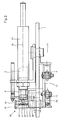
- a strip 2 of pressed cork meal which is provided on one side with an adhesive layer, which in turn is covered by a protective film 3, is fed in the direction of arrow 4 to a guide channel 5 consisting of two sheet metal strips 6 and 7.
- the drive 8 for the gradual advancement of the strip 2 consists of a friction roller 9 engaging the strip 2, a pressure roller 10 being arranged opposite.
- the rollers 9 and 10 are mounted on the base plate 1.
- a pressure medium cylinder 11 is provided, the piston 12 of which is articulated to a lever arm 13.
- the lever arm 13 is connected to the shaft of the friction roller 9 Freewheel 14 coupled so that the friction roller 9 is rotated only when the piston rod 12 is moved in the direction of arrow 15 in the sense of further transport of the strip 2 in the direction of arrow 4, whereas a return stroke of the piston rod 12 does not cause the friction roller 9 to rotate.
- a deflection 16 is provided, via which the protective film 3 is conveyed through a further guide channel 17 to a winding roller 18 after it has been pulled off the strip 2.
- a further rotary drive (not shown) is associated with the winding roller 18 in order to wind up the protective film 3.
- a cutting device 20 is provided after the deflection 16, by means of which two spacer plates 21 are cut to length from the strip.
- the cutting device 20 consists of a hollow cylinder 22 oriented perpendicular to the base plate 1 and fastened thereon, which has an inlet opening 23 and an outlet opening 24 for the strip 2.
- a partially cylindrical cutting knife 25 is received in the hollow cylinder 22 so as to be rotatable about an axis 26 perpendicular to the base plate 1.
- a pressure medium motor 27 is provided, the piston rod 28 of which is connected to a lever arm 29 pivotably mounted about the axis 26.
- a roller 30 is provided in the interior of the hollow cylinder 22 near the wall thereof, the strip 2 being passed between the surface of the cutting knife 25 facing the axis 26 and the roller 30.
- the roller 30 is mounted like the cutting knife 25 on the lever arm 29, which serves as a carrier for the components mentioned.
- a spacer plate 21 is cut to length from the strip 2 between the edge 31 of the opening 24 of the hollow cylinder 22 and the cutting edge 32 of the cutting knife 25.
- a suction head 40 is provided, which is carried by the piston rod 41 of a pressure medium cylinder 42.
- the piston rod 41 of the pressure medium cylinder 42 is hollow, so that the suction head 40 can be subjected to negative pressure.
- the pressure medium cylinder 42 is mounted on the base plate 1 so as to be freely pivotable about an axis 43 which is oriented perpendicular to the base plate 1.
- the suction head 40 By acting on the pressure medium cylinder 42, the suction head 40, which carries a spacer plate 21 cut to length from the strip 2, is moved onto the side of a glass pane of an insulating glass pane facing the device and presses the spacer plate 21 so that it sticks.
- the spacer plates 21 are placed on the side 44 of the insulating glass pane facing the device while the latter is moving in the direction of arrow 45.
- the pressure medium cylinder 42 can be freely pivoted about the axis 43 and so the suction head 40 can follow the movement of the insulating glass pane (arrow 45) during the attachment process.
- These movements are illustrated in FIG. 1 by the movement positions I, II and III of the suction head 40 shown. So that the spacer plate 21 can be placed flat on the side 44 of the insulating glass pane, the suction head 40 is movable relative to the axis 46 of the piston rod 41.
- a guide roller 50 is mounted in the vicinity of the suction head 40 on the piston rod 41 and can be freely rotated about an axis perpendicular to the base plate 1.
- the guide roller 50 is associated with a guide 51 mounted on the base plate 1 with a guide surface 52 which, when the guide roller 50 rolls along the guide surface 52, causes the suction head 40 to be moved back to the position I, starting from the position III.
- spacer plates 21 can be attached to the back of an insulating glass pane without stopping.
- the device according to the invention can also be integrated into the lateral support of a component of an insulating glass production line instead of with a horizontally oriented base plate 1 and with a substantially vertically oriented base plate.
- the suction head 40 can be briefly pressurized with compressed air in order to attach spacer plates 21 in order to attach the spacer plates 21 to the facing glass pane of an insulating glass pane under the effect of the compressed air. This measure supports the attachment of spacer plates 21.
- the suction head 40 does not have to be moved up to the facing glass pane of an insulating glass pane and can be moved with it (movement from position II to position III).
Landscapes
- Engineering & Computer Science (AREA)
- Civil Engineering (AREA)
- Structural Engineering (AREA)
- Securing Of Glass Panes Or The Like (AREA)
- Vehicle Body Suspensions (AREA)
- Circuits Of Receivers In General (AREA)
- Joining Of Glass To Other Materials (AREA)
- Laminated Bodies (AREA)
- Unwinding Webs (AREA)
- Lubricants (AREA)
- Eye Examination Apparatus (AREA)
- Soil Working Implements (AREA)
Applications Claiming Priority (2)
| Application Number | Priority Date | Filing Date | Title |
|---|---|---|---|
| AT0080188A AT390431B (de) | 1988-03-25 | 1988-03-25 | Vorrichtung zum ansetzen von distanzmitteln |
| AT801/88 | 1988-03-25 |
Publications (2)
| Publication Number | Publication Date |
|---|---|
| EP0334832A1 true EP0334832A1 (fr) | 1989-09-27 |
| EP0334832B1 EP0334832B1 (fr) | 1990-10-03 |
Family
ID=3500031
Family Applications (1)
| Application Number | Title | Priority Date | Filing Date |
|---|---|---|---|
| EP89890019A Expired - Lifetime EP0334832B1 (fr) | 1988-03-25 | 1989-01-25 | Dispositif pour appliquer des moyens d'écartement |
Country Status (5)
| Country | Link |
|---|---|
| US (1) | US4961816A (fr) |
| EP (1) | EP0334832B1 (fr) |
| AT (2) | AT390431B (fr) |
| DE (3) | DE58900016D1 (fr) |
| ES (1) | ES2018094B3 (fr) |
Cited By (4)
| Publication number | Priority date | Publication date | Assignee | Title |
|---|---|---|---|---|
| EP0873952A3 (fr) * | 1997-04-21 | 1998-12-30 | Tamglass Ltd Oy | Procédé d'intercalation de barres d'espacement entre des panneaux en verre prélaminés ainsi qu'une barre d'espacement |
| EP0997408A3 (fr) * | 1998-08-24 | 2000-08-23 | Gemtron Corporation | Procédé pour produire un tas de feuilles de verre avec éléments d'espace |
| WO2013040615A1 (fr) | 2011-09-22 | 2013-03-28 | Inova Lisec Technologiezentrum Gmbh | Dispositif pour insérer des fils espaceurs |
| CN108033054A (zh) * | 2017-11-03 | 2018-05-15 | 北京博驰自动化机械有限公司 | 一种玻璃贴垫装置及贴片方法 |
Families Citing this family (18)
| Publication number | Priority date | Publication date | Assignee | Title |
|---|---|---|---|---|
| FR2648179B1 (fr) * | 1989-06-12 | 1991-09-20 | Pont Audemer Vitrages Isolants | Procede et machine de pose automatique des joints intercalaires entre les elements d'un multiple vitrage |
| GB9022917D0 (en) * | 1990-10-22 | 1990-12-05 | Willian Design Ltd | Apparatus for turning a sheet-like workpiece |
| GB9819403D0 (en) * | 1998-09-05 | 1998-10-28 | Merritt Adrian L | Separating adhered plys |
| US6773537B2 (en) * | 2001-01-12 | 2004-08-10 | 3M Innovative Properties Company | Method for applying designs to a substrate |
| US6571849B2 (en) | 2001-01-12 | 2003-06-03 | 3M Innovative Properties Company | Tape applicator and methods of applying tape to a surface |
| US6984429B2 (en) * | 2001-01-12 | 2006-01-10 | 3M Innovative Properties Company | Laminate from which decorative films can be applied to a substrate |
| US6591988B2 (en) * | 2001-01-19 | 2003-07-15 | Cardinal Glass Industries, Inc. | Material handling for the insulating glass industry |
| US6739101B2 (en) * | 2001-01-19 | 2004-05-25 | Cardinal Ig Company | Methods and apparatus for manufacturing muntin bar assemblies |
| US6634401B2 (en) | 2001-09-27 | 2003-10-21 | 3M Innovative Properties Company | Tape applicator and methods of applying tape to a surface |
| US20030109946A1 (en) * | 2001-12-10 | 2003-06-12 | Erickson Leif O. | Computer-aided layout and application of tape |
| WO2003059790A1 (fr) * | 2002-01-15 | 2003-07-24 | Cardinal Ig Company | Procede et appareil pour manipuler des barres fragiles |
| US7712503B2 (en) * | 2005-09-12 | 2010-05-11 | Billco Manufacturing Incorporated | Automatic flexible spacer or sealant applicator for a glass work piece and method of applying flexible spacer or sealant to a glass workpiece |
| WO2009064919A1 (fr) | 2007-11-13 | 2009-05-22 | Infinite Edge Technologies, Llc | Écarteur sous forme de boîtier pourvu de parois latérales |
| DE202009008448U1 (de) | 2009-06-19 | 2009-09-03 | Grenzebach Maschinenbau Gmbh | Vorrichtung zum Entfernen der Zwischenlage senkrecht orientierter Glasplatten |
| DE102009025500B3 (de) * | 2009-06-19 | 2011-03-10 | Grenzebach Maschinenbau Gmbh | Verfahren und Vorrichtung zum Entfernen der Zwischenlage senkrecht orientierter Glasplatten |
| US8731699B2 (en) * | 2009-09-29 | 2014-05-20 | Hp3 Software, Inc. | Dynamic, lean insulated glass unit assembly line scheduler |
| IT1401245B1 (it) * | 2010-07-23 | 2013-07-12 | Nort S R L | Apparecchiatura per l'applicazione di elementi distanziali su lastre |
| CN112340455B (zh) * | 2020-11-10 | 2022-02-08 | 深圳市全洲自动化设备有限公司 | 一种为玻璃工件贴偏光片的贴片生产线 |
Citations (2)
| Publication number | Priority date | Publication date | Assignee | Title |
|---|---|---|---|---|
| DE1904875A1 (de) * | 1968-01-31 | 1969-09-11 | Triplex Safety Glass Co | Verfahren und Vorrichtung zur Gewaehrleistung des Einhaltens vorbestimmter Abstaende zwischen Glasplatten beim UEbereinanderstapeln zum Transport oder zur Lagerung |
| EP0176911A1 (fr) * | 1984-09-26 | 1986-04-09 | Karl Lenhardt | Procédé pour déposer des intercalaires sur la surface extérieure d'un vitrage multiple et dispositif pour sa mise en oeuvre |
Family Cites Families (2)
| Publication number | Priority date | Publication date | Assignee | Title |
|---|---|---|---|---|
| US2642116A (en) * | 1950-06-07 | 1953-06-16 | Johnson & Johnson | Bandage cutting and assembling machine |
| GB2130173B (en) * | 1982-11-12 | 1987-05-28 | Formost Packaging Machines Inc | Bag mouth closure and method and apparatus for making the same |
-
1988
- 1988-03-25 AT AT0080188A patent/AT390431B/de not_active IP Right Cessation
-
1989
- 1989-01-25 EP EP89890019A patent/EP0334832B1/fr not_active Expired - Lifetime
- 1989-01-25 AT AT89890019T patent/ATE57232T1/de not_active IP Right Cessation
- 1989-01-25 ES ES89890019T patent/ES2018094B3/es not_active Expired - Lifetime
- 1989-01-25 DE DE8989890019T patent/DE58900016D1/de not_active Expired - Fee Related
- 1989-02-03 DE DE8901230U patent/DE8901230U1/de not_active Expired
- 1989-02-23 US US07/313,880 patent/US4961816A/en not_active Expired - Lifetime
- 1989-02-28 DE DE3906258A patent/DE3906258A1/de active Granted
Patent Citations (2)
| Publication number | Priority date | Publication date | Assignee | Title |
|---|---|---|---|---|
| DE1904875A1 (de) * | 1968-01-31 | 1969-09-11 | Triplex Safety Glass Co | Verfahren und Vorrichtung zur Gewaehrleistung des Einhaltens vorbestimmter Abstaende zwischen Glasplatten beim UEbereinanderstapeln zum Transport oder zur Lagerung |
| EP0176911A1 (fr) * | 1984-09-26 | 1986-04-09 | Karl Lenhardt | Procédé pour déposer des intercalaires sur la surface extérieure d'un vitrage multiple et dispositif pour sa mise en oeuvre |
Cited By (10)
| Publication number | Priority date | Publication date | Assignee | Title |
|---|---|---|---|---|
| EP0873952A3 (fr) * | 1997-04-21 | 1998-12-30 | Tamglass Ltd Oy | Procédé d'intercalation de barres d'espacement entre des panneaux en verre prélaminés ainsi qu'une barre d'espacement |
| EP0997408A3 (fr) * | 1998-08-24 | 2000-08-23 | Gemtron Corporation | Procédé pour produire un tas de feuilles de verre avec éléments d'espace |
| US6220437B1 (en) | 1998-08-24 | 2001-04-24 | Gemtron Corporation | Stack of spaced sheets |
| US6488804B2 (en) | 1998-08-24 | 2002-12-03 | Gemtron Corporation | Method of manufacturing a stack of spaced lites |
| US6652945B2 (en) | 1998-08-24 | 2003-11-25 | Gemtron Corporation | Method of manufacturing a stack of spaced lites |
| US6773777B2 (en) | 1998-08-24 | 2004-08-10 | Gemtron Corporation | Method of manufacturing a stack of spaced lites |
| EP1445219A3 (fr) * | 1998-08-24 | 2004-08-25 | Gemtron Corporation | Tas de feuilles espacées |
| WO2013040615A1 (fr) | 2011-09-22 | 2013-03-28 | Inova Lisec Technologiezentrum Gmbh | Dispositif pour insérer des fils espaceurs |
| CN108033054A (zh) * | 2017-11-03 | 2018-05-15 | 北京博驰自动化机械有限公司 | 一种玻璃贴垫装置及贴片方法 |
| CN108033054B (zh) * | 2017-11-03 | 2022-05-10 | 北京博驰自动化机械有限公司 | 一种玻璃贴垫装置及贴片方法 |
Also Published As
| Publication number | Publication date |
|---|---|
| DE3906258C2 (fr) | 1991-02-14 |
| ATA80188A (de) | 1989-10-15 |
| AT390431B (de) | 1990-05-10 |
| DE3906258A1 (de) | 1989-10-12 |
| ES2018094B3 (es) | 1991-03-16 |
| DE58900016D1 (de) | 1990-11-08 |
| ATE57232T1 (de) | 1990-10-15 |
| EP0334832B1 (fr) | 1990-10-03 |
| US4961816A (en) | 1990-10-09 |
| DE8901230U1 (de) | 1989-03-30 |
Similar Documents
| Publication | Publication Date | Title |
|---|---|---|
| AT390431B (de) | Vorrichtung zum ansetzen von distanzmitteln | |
| DE69710099T2 (de) | Vorrichtung und verfahren zum automatisierten auftragen eines abstandhalters | |
| DE3637561C2 (fr) | ||
| DE69401659T2 (de) | Vorrichtung zum ankleben des freien endes einer rolle aus bahnmaterial | |
| DE19839924C2 (de) | Vorrichtung zur Abnahme von Folien von einem Folienstapel in einer Stapelstation und zur Ablage der abgenommenen Folien in einer Zusammenlegestation | |
| DE3636767C2 (fr) | ||
| DE2905841A1 (de) | Verfahren und vorrichtung zur herstellung von verbundplatten, insbesondere verbundglasscheiben | |
| DE68922482T2 (de) | Auflegevorrichtung für gummierte Bahnen. | |
| DE2731691C2 (de) | Vorrichtung zum Herstellen einer räumlich geformten Verkleidungsplatte | |
| CH540157A (de) | Einrichtung zum Ankleben eines Klebebandes an Artikeln | |
| EP0364837B1 (fr) | Dispositif d'étiquetage pour opposer une étiquette sur un support, en particulier une étiquette de grand format sur un rouleau de papier ainsi que méthode d'application | |
| CH679576A5 (fr) | ||
| DE3515729A1 (de) | Platteneinschiebevorrichtung zum einschieben von auf einem hubtisch abgelegten plattenfoermigen werkstuecken in plattenaufteilanlagen | |
| DE3601296A1 (de) | Vorrichtung zum automatischen ansetzen einer warenbahn in einer beschickungsvorrichtung | |
| DE69900525T2 (de) | Vorrichtung und Verfahren zum Entfernen des Verpackungsmaterials von einer Materialbahnrolle | |
| DE3217247C2 (fr) | ||
| DE1586093B2 (de) | Vorrichtung zum aufbringen von aufreisstreifen auf ein einschlagmaterialband | |
| DE2605197C2 (de) | Vorrichtung zum Stapeln von insbesondere gewölbten Glasscheiben mit Papierzwischenlagen | |
| DE3119109C2 (de) | Vorrichtung zum Wechseln von Vorratsrollen in einer Etikettiermaschine | |
| DE3730923A1 (de) | Aggregat zum zuschneiden und zusammensetzen von streifenmaterial | |
| DE2719957C3 (de) | Etikettiervorrichtung | |
| EP1422174B1 (fr) | Méthode et dispositif pour la préparation d'une bobine de papier pour collage au vol | |
| DE3503715C2 (fr) | ||
| DE3245154A1 (de) | Vorrichtung zur foerderung von etiketten | |
| DE19839923C2 (de) | Vorrichtung zur Abnahme von Folien von einem Folienstapel in einer Stapelstation und zur Ablage der abgenommenen Folien in einer Zusammenlegestation |
Legal Events
| Date | Code | Title | Description |
|---|---|---|---|
| PUAI | Public reference made under article 153(3) epc to a published international application that has entered the european phase |
Free format text: ORIGINAL CODE: 0009012 |
|
| AK | Designated contracting states |
Kind code of ref document: A1 Designated state(s): AT BE CH DE ES FR GB GR IT LI LU NL SE |
|
| 17P | Request for examination filed |
Effective date: 19891026 |
|
| 17Q | First examination report despatched |
Effective date: 19891212 |
|
| GRAA | (expected) grant |
Free format text: ORIGINAL CODE: 0009210 |
|
| ITF | It: translation for a ep patent filed | ||
| AK | Designated contracting states |
Kind code of ref document: B1 Designated state(s): AT BE CH DE ES FR GB GR IT LI LU NL SE |
|
| PG25 | Lapsed in a contracting state [announced via postgrant information from national office to epo] |
Ref country code: GR Free format text: LAPSE BECAUSE OF FAILURE TO SUBMIT A TRANSLATION OF THE DESCRIPTION OR TO PAY THE FEE WITHIN THE PRESCRIBED TIME-LIMIT Effective date: 19901003 |
|
| REF | Corresponds to: |
Ref document number: 57232 Country of ref document: AT Date of ref document: 19901015 Kind code of ref document: T |
|
| ET | Fr: translation filed | ||
| GBT | Gb: translation of ep patent filed (gb section 77(6)(a)/1977) | ||
| REF | Corresponds to: |
Ref document number: 58900016 Country of ref document: DE Date of ref document: 19901108 |
|
| ITTA | It: last paid annual fee | ||
| PLBE | No opposition filed within time limit |
Free format text: ORIGINAL CODE: 0009261 |
|
| STAA | Information on the status of an ep patent application or granted ep patent |
Free format text: STATUS: NO OPPOSITION FILED WITHIN TIME LIMIT |
|
| 26N | No opposition filed | ||
| EPTA | Lu: last paid annual fee | ||
| EAL | Se: european patent in force in sweden |
Ref document number: 89890019.6 |
|
| REG | Reference to a national code |
Ref country code: CH Ref legal event code: PFA Free format text: LISEC MASCHINENBAU GESELLSCHAFT M.B.H. |
|
| REG | Reference to a national code |
Ref country code: FR Ref legal event code: CD Ref country code: FR Ref legal event code: CA |
|
| NLT1 | Nl: modifications of names registered in virtue of documents presented to the patent office pursuant to art. 16 a, paragraph 1 |
Owner name: LISEC MASCHINENBAU GMBH |
|
| REG | Reference to a national code |
Ref country code: GB Ref legal event code: IF02 |
|
| PGFP | Annual fee paid to national office [announced via postgrant information from national office to epo] |
Ref country code: SE Payment date: 20031230 Year of fee payment: 16 Ref country code: FR Payment date: 20031230 Year of fee payment: 16 |
|
| PGFP | Annual fee paid to national office [announced via postgrant information from national office to epo] |
Ref country code: NL Payment date: 20040116 Year of fee payment: 16 |
|
| PGFP | Annual fee paid to national office [announced via postgrant information from national office to epo] |
Ref country code: ES Payment date: 20040123 Year of fee payment: 16 |
|
| PGFP | Annual fee paid to national office [announced via postgrant information from national office to epo] |
Ref country code: BE Payment date: 20040127 Year of fee payment: 16 |
|
| PGFP | Annual fee paid to national office [announced via postgrant information from national office to epo] |
Ref country code: LU Payment date: 20040130 Year of fee payment: 16 |
|
| PG25 | Lapsed in a contracting state [announced via postgrant information from national office to epo] |
Ref country code: IT Free format text: LAPSE BECAUSE OF NON-PAYMENT OF DUE FEES;WARNING: LAPSES OF ITALIAN PATENTS WITH EFFECTIVE DATE BEFORE 2007 MAY HAVE OCCURRED AT ANY TIME BEFORE 2007. THE CORRECT EFFECTIVE DATE MAY BE DIFFERENT FROM THE ONE RECORDED. Effective date: 20050125 Ref country code: LU Free format text: LAPSE BECAUSE OF NON-PAYMENT OF DUE FEES Effective date: 20050125 |
|
| PG25 | Lapsed in a contracting state [announced via postgrant information from national office to epo] |
Ref country code: ES Free format text: LAPSE BECAUSE OF NON-PAYMENT OF DUE FEES Effective date: 20050126 Ref country code: SE Free format text: LAPSE BECAUSE OF NON-PAYMENT OF DUE FEES Effective date: 20050126 |
|
| PG25 | Lapsed in a contracting state [announced via postgrant information from national office to epo] |
Ref country code: BE Free format text: LAPSE BECAUSE OF NON-PAYMENT OF DUE FEES Effective date: 20050131 |
|
| BERE | Be: lapsed |
Owner name: *MAWAK WARENHANDELS G.M.B.H. Effective date: 20050131 |
|
| PG25 | Lapsed in a contracting state [announced via postgrant information from national office to epo] |
Ref country code: NL Free format text: LAPSE BECAUSE OF NON-PAYMENT OF DUE FEES Effective date: 20050801 |
|
| EUG | Se: european patent has lapsed | ||
| PG25 | Lapsed in a contracting state [announced via postgrant information from national office to epo] |
Ref country code: FR Free format text: LAPSE BECAUSE OF NON-PAYMENT OF DUE FEES Effective date: 20050930 |
|
| NLV4 | Nl: lapsed or anulled due to non-payment of the annual fee |
Effective date: 20050801 |
|
| REG | Reference to a national code |
Ref country code: FR Ref legal event code: ST |
|
| PGFP | Annual fee paid to national office [announced via postgrant information from national office to epo] |
Ref country code: DE Payment date: 20060112 Year of fee payment: 18 |
|
| PGFP | Annual fee paid to national office [announced via postgrant information from national office to epo] |
Ref country code: CH Payment date: 20060113 Year of fee payment: 18 |
|
| PGFP | Annual fee paid to national office [announced via postgrant information from national office to epo] |
Ref country code: GB Payment date: 20060120 Year of fee payment: 18 |
|
| PGFP | Annual fee paid to national office [announced via postgrant information from national office to epo] |
Ref country code: AT Payment date: 20060124 Year of fee payment: 18 |
|
| REG | Reference to a national code |
Ref country code: ES Ref legal event code: FD2A Effective date: 20050126 |
|
| PG25 | Lapsed in a contracting state [announced via postgrant information from national office to epo] |
Ref country code: LI Free format text: LAPSE BECAUSE OF NON-PAYMENT OF DUE FEES Effective date: 20070131 Ref country code: CH Free format text: LAPSE BECAUSE OF NON-PAYMENT OF DUE FEES Effective date: 20070131 |
|
| PG25 | Lapsed in a contracting state [announced via postgrant information from national office to epo] |
Ref country code: DE Free format text: LAPSE BECAUSE OF NON-PAYMENT OF DUE FEES Effective date: 20070801 |
|
| REG | Reference to a national code |
Ref country code: CH Ref legal event code: PL |
|
| GBPC | Gb: european patent ceased through non-payment of renewal fee |
Effective date: 20070125 |
|
| PG25 | Lapsed in a contracting state [announced via postgrant information from national office to epo] |
Ref country code: AT Free format text: LAPSE BECAUSE OF NON-PAYMENT OF DUE FEES Effective date: 20070125 Ref country code: GB Free format text: LAPSE BECAUSE OF NON-PAYMENT OF DUE FEES Effective date: 20070125 |
|
| BERE | Be: lapsed |
Owner name: *MAWAK WARENHANDELS G.M.B.H. Effective date: 20050131 |
|
| PGFP | Annual fee paid to national office [announced via postgrant information from national office to epo] |
Ref country code: IT Payment date: 20060131 Year of fee payment: 18 |
|
| PGRI | Patent reinstated in contracting state [announced from national office to epo] |
Ref country code: IT Effective date: 20080301 |
|
| PGRI | Patent reinstated in contracting state [announced from national office to epo] |
Ref country code: IT Effective date: 20080301 |