EP0334909B1 - Engrenage reducteur pour vehicules a moteur - Google Patents
Engrenage reducteur pour vehicules a moteur Download PDFInfo
- Publication number
- EP0334909B1 EP0334909B1 EP88907614A EP88907614A EP0334909B1 EP 0334909 B1 EP0334909 B1 EP 0334909B1 EP 88907614 A EP88907614 A EP 88907614A EP 88907614 A EP88907614 A EP 88907614A EP 0334909 B1 EP0334909 B1 EP 0334909B1
- Authority
- EP
- European Patent Office
- Prior art keywords
- gear
- friction surface
- synchronising
- ring
- step reduction
- Prior art date
- Legal status (The legal status is an assumption and is not a legal conclusion. Google has not performed a legal analysis and makes no representation as to the accuracy of the status listed.)
- Expired - Lifetime
Links
- 230000000284 resting effect Effects 0.000 claims 1
- 238000000034 method Methods 0.000 abstract description 9
- 230000008569 process Effects 0.000 abstract description 9
- 230000001360 synchronised effect Effects 0.000 abstract description 7
- 230000002093 peripheral effect Effects 0.000 abstract description 4
- 230000005540 biological transmission Effects 0.000 description 9
- 238000006073 displacement reaction Methods 0.000 description 8
- 230000008901 benefit Effects 0.000 description 7
- 230000008859 change Effects 0.000 description 3
- 238000010586 diagram Methods 0.000 description 2
- 230000007257 malfunction Effects 0.000 description 2
- 230000007935 neutral effect Effects 0.000 description 2
- 230000009471 action Effects 0.000 description 1
- 210000000078 claw Anatomy 0.000 description 1
- 230000000295 complement effect Effects 0.000 description 1
- 230000006378 damage Effects 0.000 description 1
- 230000000694 effects Effects 0.000 description 1
- 238000012986 modification Methods 0.000 description 1
- 230000004048 modification Effects 0.000 description 1
- 238000003199 nucleic acid amplification method Methods 0.000 description 1
- 230000000717 retained effect Effects 0.000 description 1
Images
Classifications
-
- F—MECHANICAL ENGINEERING; LIGHTING; HEATING; WEAPONS; BLASTING
- F16—ENGINEERING ELEMENTS AND UNITS; GENERAL MEASURES FOR PRODUCING AND MAINTAINING EFFECTIVE FUNCTIONING OF MACHINES OR INSTALLATIONS; THERMAL INSULATION IN GENERAL
- F16D—COUPLINGS FOR TRANSMITTING ROTATION; CLUTCHES; BRAKES
- F16D23/00—Details of mechanically-actuated clutches not specific for one distinct type
- F16D23/02—Arrangements for synchronisation, also for power-operated clutches
- F16D23/04—Arrangements for synchronisation, also for power-operated clutches with an additional friction clutch
- F16D23/06—Arrangements for synchronisation, also for power-operated clutches with an additional friction clutch and a blocking mechanism preventing the engagement of the main clutch prior to synchronisation
-
- F—MECHANICAL ENGINEERING; LIGHTING; HEATING; WEAPONS; BLASTING
- F16—ENGINEERING ELEMENTS AND UNITS; GENERAL MEASURES FOR PRODUCING AND MAINTAINING EFFECTIVE FUNCTIONING OF MACHINES OR INSTALLATIONS; THERMAL INSULATION IN GENERAL
- F16D—COUPLINGS FOR TRANSMITTING ROTATION; CLUTCHES; BRAKES
- F16D23/00—Details of mechanically-actuated clutches not specific for one distinct type
- F16D23/02—Arrangements for synchronisation, also for power-operated clutches
- F16D23/04—Arrangements for synchronisation, also for power-operated clutches with an additional friction clutch
- F16D23/06—Arrangements for synchronisation, also for power-operated clutches with an additional friction clutch and a blocking mechanism preventing the engagement of the main clutch prior to synchronisation
- F16D2023/0631—Sliding sleeves; Details thereof
-
- F—MECHANICAL ENGINEERING; LIGHTING; HEATING; WEAPONS; BLASTING
- F16—ENGINEERING ELEMENTS AND UNITS; GENERAL MEASURES FOR PRODUCING AND MAINTAINING EFFECTIVE FUNCTIONING OF MACHINES OR INSTALLATIONS; THERMAL INSULATION IN GENERAL
- F16D—COUPLINGS FOR TRANSMITTING ROTATION; CLUTCHES; BRAKES
- F16D23/00—Details of mechanically-actuated clutches not specific for one distinct type
- F16D23/02—Arrangements for synchronisation, also for power-operated clutches
- F16D23/04—Arrangements for synchronisation, also for power-operated clutches with an additional friction clutch
- F16D23/06—Arrangements for synchronisation, also for power-operated clutches with an additional friction clutch and a blocking mechanism preventing the engagement of the main clutch prior to synchronisation
- F16D2023/0637—Details relating to the hub member on which the sliding is arranged
-
- F—MECHANICAL ENGINEERING; LIGHTING; HEATING; WEAPONS; BLASTING
- F16—ENGINEERING ELEMENTS AND UNITS; GENERAL MEASURES FOR PRODUCING AND MAINTAINING EFFECTIVE FUNCTIONING OF MACHINES OR INSTALLATIONS; THERMAL INSULATION IN GENERAL
- F16D—COUPLINGS FOR TRANSMITTING ROTATION; CLUTCHES; BRAKES
- F16D23/00—Details of mechanically-actuated clutches not specific for one distinct type
- F16D23/02—Arrangements for synchronisation, also for power-operated clutches
- F16D23/04—Arrangements for synchronisation, also for power-operated clutches with an additional friction clutch
- F16D23/06—Arrangements for synchronisation, also for power-operated clutches with an additional friction clutch and a blocking mechanism preventing the engagement of the main clutch prior to synchronisation
- F16D2023/0656—Details of the tooth structure; Arrangements of teeth
-
- F—MECHANICAL ENGINEERING; LIGHTING; HEATING; WEAPONS; BLASTING
- F16—ENGINEERING ELEMENTS AND UNITS; GENERAL MEASURES FOR PRODUCING AND MAINTAINING EFFECTIVE FUNCTIONING OF MACHINES OR INSTALLATIONS; THERMAL INSULATION IN GENERAL
- F16D—COUPLINGS FOR TRANSMITTING ROTATION; CLUTCHES; BRAKES
- F16D23/00—Details of mechanically-actuated clutches not specific for one distinct type
- F16D23/02—Arrangements for synchronisation, also for power-operated clutches
- F16D23/04—Arrangements for synchronisation, also for power-operated clutches with an additional friction clutch
- F16D23/06—Arrangements for synchronisation, also for power-operated clutches with an additional friction clutch and a blocking mechanism preventing the engagement of the main clutch prior to synchronisation
- F16D2023/0656—Details of the tooth structure; Arrangements of teeth
- F16D2023/0662—Details relating to special geometry of arrangements of teeth
-
- Y—GENERAL TAGGING OF NEW TECHNOLOGICAL DEVELOPMENTS; GENERAL TAGGING OF CROSS-SECTIONAL TECHNOLOGIES SPANNING OVER SEVERAL SECTIONS OF THE IPC; TECHNICAL SUBJECTS COVERED BY FORMER USPC CROSS-REFERENCE ART COLLECTIONS [XRACs] AND DIGESTS
- Y10—TECHNICAL SUBJECTS COVERED BY FORMER USPC
- Y10T—TECHNICAL SUBJECTS COVERED BY FORMER US CLASSIFICATION
- Y10T74/00—Machine element or mechanism
- Y10T74/19—Gearing
- Y10T74/19219—Interchangeably locked
- Y10T74/19284—Meshing assisters
Definitions
- the invention relates to a multi-step transmission for motor vehicles, with a first gear and a second gear, which are arranged next to one another on a common shaft, with synchronization means arranged between the gear wheels and axially displaceable relative to these for adjusting the speeds of the gear wheels, an actuating element of the synchronization means rotates with the first gear, this is rotatable by a limited angle and has a circumferential friction surface which can be brought into frictional engagement by axial displacement with a counter-friction surface of the second gear and furthermore has a first wedge surface inclined to the radial plane which bears against an assigned second wedge surface.
- Step gears of the type mentioned above are generally known as so-called lock-synchronized step gears.
- the first gearwheel is rotatably fixed and the second gearwheel is rotatably arranged on the shaft.
- the second gear meshes with a third gear which is arranged in a rotationally fixed manner on a second shaft parallel to the first shaft.
- the synchronization means are usually designed as synchronizer rings, which rotate with the first gear and can be rotated relative to the latter over a small range of rotation angles.
- a gearshift sleeve can be displaced by means of a gearshift fork over the external teeth of the gearwheels, the gearshift sleeve having internal teeth or internal claws which engage in a form-fitting manner in the external teeth of the first and second gearwheels and are therefore torsionally rigid connects with each other.
- the shift sleeve pushes the synchronizer ring with a usually conical friction surface against a counter surface on the second gear, so that when the speed difference between the first and second gear is generated, a friction torque is generated which relies on the synchronizer ring relative to the first gear finite angle of rotation twisted.
- the synchronizer ring blocks the further axial displacement of the shift sleeve, so that the gear in question cannot be engaged unless the speed of rotation is the same between the first and the second gear. Only when this is the case, i.e.
- the friction torque has become zero, can the synchronizer ring turn back to the untwisted starting position, for example under the force of a corresponding return spring, and the axial displacement path for the gearshift sleeve is free to now do the first and that bring the second gear in positive engagement with each other and thus engage the desired gear.
- the synchronization process largely depends on it depends on how the driver of the motor vehicle performs the gear change by operating the shift lever. If the shift sleeve is moved relatively vigorously and the synchronizer ring is consequently brought into contact with the counter surface of the second gearwheel with a high contact pressure, a relatively large frictional torque is produced immediately, and the speed adjustment takes place relatively quickly. Conversely, the speeds adjust very slowly to one another if the shift sleeve is deflected only with a small axial actuating force. Naturally, this has an impact on the shifting time, because the speed gradient of the wheel to be braked or accelerated depends on the magnitude of the frictional torque and directly influences the shifting time.
- the invention is based on the object of developing a step transmission of the type mentioned in such a way that the synchronization process takes place independently of the shifting force exerted by the driver and malfunctions are avoided.
- the second gear meshes with another, on a second shaft parallel to the second shaft rotatably arranged third gear that the first gear rotates with a synchronizer ring, that a first friction surface on the synchronizer ring with a counter-friction surface on second gear cooperates and that a shift sleeve can be slid positively over the first and second gear.
- the object underlying the invention is completely achieved in this way.
- the driver only needs the synchronization process when shifting the multi-step transmission by applying the Initiate friction surfaces against each other, because the resulting friction torque immediately leads to an axial deflection of the actuating element via the wedge gear provided according to the invention, and the axial deflection in turn increases the friction torque in a targeted manner.
- an automatically occurring friction torque curve can be preselected over time, which ensures that the synchronization process is always the same.
- the invention has the further advantage that a constant switching time can be specified, and the wear can also be set constantly, so that the life of the elements can be precisely calculated in advance.
- the invention has the advantage that a significant contribution to the automation of step gears with spur gear teeth and traction interruption is made, because in the self-regulation of the synchronization process described above, only the impetus to initiate the synchronization must be given, which o by a simple mechanical pulse generator . Like. depending on an electronic control unit can be easily achieved.
- the one synchronizer ring is now locked with respect to the other, so that there can be no malfunction and thus destruction of the synchronizing device.
- one synchronizer ring is locked against the other that is being moved, so that the stationary synchronizer ring cannot mechanically move out of its position.
- the invention can be integrated into existing gears without any problems, because only relatively minor modifications to the synchronizer ring and to the gears or the gearshift sleeve are required.
- synchronizer rings are arranged on both sides of the first gearwheel, and locking means are provided in order to axially lock the other synchronizer ring when a synchronizer ring is moved.
- This measure has the advantage that the advantages according to the invention are retained in the known arrangement of two synchronizer rings on both sides of a gear and a shift sleeve which can be displaced in both directions to the gear. Due to the self-regulating synchronization process with automatically increasing friction torque, care must be taken to ensure that none of the synchronizer rings with its friction surface, even if only briefly, comes into engagement with the counter-friction surface in order to avoid undesired synchronizations in the transmission. The features mentioned above provide a remedy here because the locking means reliably prevent the inadvertent axial displacement of the synchronizer rings.
- the locking means are designed as a ball lock, in which a ball is partially arranged in an opening in the synchronizing ring, the diameter of the ball being greater than the radial thickness of the synchronizing ring in the region of the opening, and further the ball in the rest either engages only in a radial recess of the first gear or only in a radial recess of the shift sleeve.
- the synchronizer rings are provided with an elastic ring on which the shift sleeve engages in order to bring one of the synchronizer rings into engagement with its friction surface on the counter surface.
- This measure has the advantage that a pre-synchronization is achieved because the engagement of the shift sleeve on the elastic ring also achieves a frictional torque between the synchronizer ring and the shift sleeve, over the already mentioned, limited, limited angle of rotation.
- the shift sleeve and the synchronizer ring are each provided with locking elements which at least partially overlap in the axial direction when the shift sleeve and the synchronizer ring are rotated relative to one another and block an axial displacement of the shift sleeve beyond a predetermined position how this is known per se.
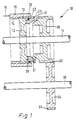
- Fig. 1 10 denotes a spur gear, lock-synchronized step transmission of a motor vehicle.
- a first shaft 11 On a first shaft 11 is a non-rotatable and axially fixed arranged first gear 12 which engages with its external toothing 13 in an internal toothing 14 of a shift sleeve 15, which is axially displaceable, as indicated by an arrow 16.
- a synchronizer ring 20 which rotates with the first gear 12 and is relatively rotatable relative to the latter by a certain angle of rotation.
- the synchronizer ring 20 has a conical friction surface 21 on the side facing away from the first gear 12.
- Locking elements 22 and 23 are respectively attached to the shift sleeve 15 and to the synchronizer ring 20.
- the locking elements 22, 23 are designed in the manner of teeth. They block an axial movement of the shift sleeve 15 beyond the right-hand end face of the synchronizer ring 20 in FIG. 1 when the synchronizer ring 20 is rotated relative to the first gear 12, while they are aligned with one another in the untwisted state and thus do not impede the axial path of the shift sleeve 15 .
- wedge surfaces are provided on the circumference, which are inclined to a radial plane of the shaft 11 and are in engagement with one another. These wedge surfaces form a circumferential wedge gearing, which is only indicated in FIG. 1 by 25.
- a second gear 30 is freely rotatable, but axially fixed, arranged on the first shaft 11, in FIG. 1 to the right of the synchronizer ring 20.
- the second gear 30 has a counter surface 31, which is also conical and parallel runs to the friction surface 21 of the synchronizer ring 20.
- the counter surface 31 is located at an axial distance from the friction surface 21, but this distance is shown exaggeratedly large in FIG. 1 for the sake of clarity.
- the second gearwheel 30 is provided with an external toothing 32 which meshes with a corresponding external toothing 33 of a third gearwheel 34 which is arranged in a rotationally fixed and axially fixed manner on a second shaft 35 which runs parallel to the first shaft 11.
- the shift sleeve 15 is displaced in the direction of the arrow 16 and takes the synchronizer ring 20 axially.
- a friction torque arises due to the speed difference between the gears 12 and 30.
- This friction torque rotates the synchronizer ring 20 with respect to the first gear 12.
- the locking elements 22, 23 prevent the shift sleeve 15 from being axially displaced from this point on, so that the only frictional connection between the first gear 12 and the second gear 30 is the frictional engagement of the friction surfaces 21/31.
- the speeds of the gear wheels 12, 30 adjust until the friction torque at the speed difference zero also becomes zero and the synchronizer ring 20 can turn back into the starting position.
- the locking elements 22, 23 are now aligned with one another and are no longer in the way of further axial displacement of the shift sleeve 15.
- the shift sleeve 15 can now be pushed to the right in FIG. 1 so that its internal toothing 14 also detects the external toothing 32 of the second gear 30 in its left half.
- the gears 12 and 30 are thus coupled in a torsionally rigid manner, so that a torque transmission from the first shaft 11 to the second shaft 35 takes place via the translation of the gears 30/34.
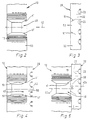
- the circumferential wedge gear 25 is provided, which will be explained below with reference to FIGS. 2 to 7.
- the first gear 12 is provided at one (or more) circumferential positions with a trapezoidal receptacle 40, which is limited in the circumferential direction by first peripheral wedge surfaces 41 and 41 '.
- the receptacle 40 runs symmetrically to a center line 42, which in turn runs parallel to the first shaft 11.
- Fig. 3 shows the associated section of the synchronizer ring 20, which is shaped with a complementary to the receptacle 40 Projection 50 is provided.
- the projection 50 is provided with second peripheral wedge surfaces 51 and 51 '.
- the first gear 12 and the synchronizer ring 20 axially partially overlap one another when they are idling or in a synchronized operating position.
- the synchronizer ring 20 is provided with a slightly reduced outer first running surface 52, while the first gear 12 is provided with a corresponding second, inner running surface 53.
- Fig. 3 shows the above-mentioned state when idling or synchronous running, in which the projection 50 fits positively into the receptacle 40 and the associated wedge surfaces 41/51 and 41 '/ 51' lie against each other. Seen in the circumferential direction, there is symmetry in relation to the common center line 42 in this case.
- FIG. 5 shows such an operating state in which the rotation (seen from the right in FIG. 5) takes place in such a way that the synchronizer ring 20 rotates in a clockwise direction with respect to the first gear 12.
- the first wedge surface 41 of the first gear wheel 12 now slides on the associated second wedge surface 51 of the synchronizer ring 20, which leads to an axial deflection z of the synchronizer ring 20 with respect to the axially rigid first gear wheel 12 when rotated relative to a circumferential section u.
- the center lines 42a, 42b are in in this case offset by the circumferential section u from one another.
- the function of the locking elements 22 and 23 can also be seen by comparing FIGS. 3 and 5.
- the locking elements 22 and 23 are on a gap, so that they do not stand in the way of an axial displacement of the shift sleeve 15.
- the locking elements 22, 23 partially overlap one another in the axial direction, so that a further displacement of the shift sleeve 15 beyond a predetermined axial position is not possible. In this way, unsynchronized switching errors are avoided because the internal toothing 14 of the shift sleeve 15 cannot be brought into engagement with the external toothing 32 of the second gear 30.
- a constant K can be set which is greater than 1.
- there is a self-amplification or positive feedback of the frictional torque which increases in a controlled manner to a maximum value until finally synchronous running between the first gear 12, the synchronizer ring 20 and the second gear 30 occurs.
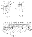
- Fig. 8 shows a detail of an embodiment in which on both sides of a first gear 12 'synchronizer rings 20a and 20b are arranged.
- a mutual locking is provided in order to avoid uncontrolled synchronizations that would occur if one of the synchronizer rings 20a or 20b accidentally came into frictional engagement with the respectively associated gear.
- the lock consists of a ball lock, which is formed by radial recesses 60a, 60b in the first gear 12 ', balls 61a, 61b, openings 62a, 62b in the synchronizer rings 20a, 20b and a common radial recess 64 in the shift sleeve 15'.
- the diameter of the balls 61a, 61b is significantly larger than the radial thickness of the synchronizer rings 20a, 20b in the area of the openings 62a, 62b.
- the path of the balls 61a, 61b upwards is blocked by an inner surface 63 of the shift sleeve 15 ', so that the balls 61a, 61b partially engage in the radial recesses 60a, 60b of the first gear 12' and thus axially lock both synchronizer rings 20a, 20b.
- the synchronizer ring 20b is now shifted to the left and reaches the associated counter surface 31b with its friction surface 21b, after which the synchronization process described in detail above occurs.
- the recess 64 takes the ball 61b and thus also the synchronizer ring 20b with a lateral boundary flank 67 until the ball 61b falls back into the radial recess 60b and the synchronizer ring 20b is thus locked again.
- the synchronizer ring can also be made for the synchronizer ring to rotate with the second gear 30 and to provide a counter-friction surface on the first gear 12. It is also conceivable to let the wedge transmission take effect between the shift sleeve and the synchronizer ring instead of between the first gear and the synchronizer ring. Furthermore, it is possible to divide the synchronizer ring into functions of an actuating element and a friction element, the actuating element rotating with a gearwheel and being rotatable relative to it and axially displaceable under the action of the wedge gear, while the friction element as a "floating" synchronizing ring between two counter surfaces is arranged on the actuating element and on the counter gear.
Landscapes
- Engineering & Computer Science (AREA)
- General Engineering & Computer Science (AREA)
- Mechanical Engineering (AREA)
- Mechanical Operated Clutches (AREA)
- Structure Of Transmissions (AREA)
Abstract
Claims (5)
Applications Claiming Priority (2)
| Application Number | Priority Date | Filing Date | Title |
|---|---|---|---|
| DE3732525 | 1987-09-26 | ||
| DE19873732525 DE3732525A1 (de) | 1987-09-26 | 1987-09-26 | Stufengetriebe fuer kraftfahrzeuge |
Publications (2)
| Publication Number | Publication Date |
|---|---|
| EP0334909A1 EP0334909A1 (fr) | 1989-10-04 |
| EP0334909B1 true EP0334909B1 (fr) | 1992-01-22 |
Family
ID=6336977
Family Applications (1)
| Application Number | Title | Priority Date | Filing Date |
|---|---|---|---|
| EP88907614A Expired - Lifetime EP0334909B1 (fr) | 1987-09-26 | 1988-09-21 | Engrenage reducteur pour vehicules a moteur |
Country Status (5)
| Country | Link |
|---|---|
| US (1) | US5003834A (fr) |
| EP (1) | EP0334909B1 (fr) |
| JP (1) | JPH02503592A (fr) |
| DE (2) | DE3732525A1 (fr) |
| WO (1) | WO1989002995A1 (fr) |
Families Citing this family (5)
| Publication number | Priority date | Publication date | Assignee | Title |
|---|---|---|---|---|
| US5544727A (en) * | 1993-12-27 | 1996-08-13 | Eaton Corporation | Synchronizer with self-energizing |
| DE19702541B4 (de) * | 1996-02-01 | 2005-04-07 | Volkswagen Ag | Zweiteiliges Gangrad für Schaltgetriebe |
| SE514231C2 (sv) * | 2000-01-28 | 2001-01-29 | Scania Cv Ab | Synkroniseringsanordning vid en planetväxel |
| JP4569261B2 (ja) * | 2004-10-28 | 2010-10-27 | 日産自動車株式会社 | 変速機の同期装置 |
| NZ734076A (en) | 2015-02-23 | 2022-10-28 | Dynomax Drilling Tools Inc Canada | Downhole flow diversion device with oscillation damper |
Family Cites Families (12)
| Publication number | Priority date | Publication date | Assignee | Title |
|---|---|---|---|---|
| US3414098A (en) * | 1966-10-05 | 1968-12-03 | Borg Warner | Positive clutch with multiple friction synchronizing disks |
| GB1273898A (en) * | 1969-12-29 | 1972-05-10 | Honda Motor Co Ltd | Improvements in or relating to change gear mechanisms incorporating synchromesh |
| FR2106789A5 (fr) * | 1970-09-24 | 1972-05-05 | Peugeot & Renault | |
| FR2250404A5 (en) * | 1973-10-31 | 1975-05-30 | Citroen Sa | Synchroniser for a gearbox - tension springs normally prevent contact between pinion and synchronising ring |
| DD111449A1 (fr) * | 1973-11-12 | 1975-02-12 | ||
| DE2659448C2 (de) * | 1976-12-30 | 1981-11-26 | Getrag Getriebe- Und Zahnradfabrik Gmbh, 7140 Ludwigsburg | Synchronisiereinrichtung für Schaltkupplungen, insbes. von Schaltgetrieben |
| DE2751699C3 (de) * | 1977-11-19 | 1981-03-12 | Volkswagenwerk Ag, 3180 Wolfsburg | Einrichtung zur geräuschlosen Schaltung eines Rückwärtsganges von Geschwindigkeitswechselgetrieben, insbesondere von Kraftfahrzeugen |
| DE3125424C2 (de) * | 1981-06-27 | 1984-10-25 | Zahnradfabrik Friedrichshafen Ag, 7990 Friedrichshafen | Sperr-Synchronisierung für Schaltgetriebe |
| DE3411351C1 (de) * | 1984-03-28 | 1985-11-07 | Getrag Getriebe- Und Zahnradfabrik Gmbh, 7140 Ludwigsburg | Synchronisiereinrichtungen fuer Schaltkupplungen |
| JPS612922A (ja) * | 1984-06-14 | 1986-01-08 | Honda Motor Co Ltd | イナ−シヤロツク型同期クラツチ装置 |
| DE3444670C1 (de) * | 1984-12-07 | 1986-07-17 | Getrag Getriebe- Und Zahnradfabrik Gmbh, 7140 Ludwigsburg | Synchronisiereinrichtung fuer Schaltkupplungen |
| JPS6367447A (ja) * | 1986-09-09 | 1988-03-26 | Mazda Motor Corp | 歯車式変速機のリバ−ス構造 |
-
1987
- 1987-09-26 DE DE19873732525 patent/DE3732525A1/de not_active Withdrawn
-
1988
- 1988-09-21 JP JP88507191A patent/JPH02503592A/ja active Pending
- 1988-09-21 DE DE8888907614T patent/DE3868050D1/de not_active Expired - Fee Related
- 1988-09-21 US US07/372,344 patent/US5003834A/en not_active Expired - Fee Related
- 1988-09-21 WO PCT/DE1988/000585 patent/WO1989002995A1/fr not_active Ceased
- 1988-09-21 EP EP88907614A patent/EP0334909B1/fr not_active Expired - Lifetime
Also Published As
| Publication number | Publication date |
|---|---|
| US5003834A (en) | 1991-04-02 |
| EP0334909A1 (fr) | 1989-10-04 |
| JPH02503592A (ja) | 1990-10-25 |
| WO1989002995A1 (fr) | 1989-04-06 |
| DE3868050D1 (de) | 1992-03-05 |
| DE3732525A1 (de) | 1989-04-06 |
Similar Documents
| Publication | Publication Date | Title |
|---|---|---|
| DE2512248C3 (de) | Sperrsynchronisationseinrichtung für ein Wechselgetriebe | |
| EP3472484B1 (fr) | Dispositif de synchronisation pour une boîte de vitesses manuelle | |
| DE4324814A1 (de) | Getriebeschaltung mit Sperrsynchronisierung | |
| EP2475906A1 (fr) | Dispositif de synchronisation pour boîte de vitesses | |
| EP0812398B1 (fr) | Synchronisation de disques | |
| DE102007022544B4 (de) | Schaltkupplungsanordnung | |
| DE1630457A1 (de) | Mehrganggetriebe mit von Hand betaetigter Synchronisiervorrichtung | |
| EP1199489B1 (fr) | Boîte de vitesses synchronisées et bague conique correspondant | |
| EP0334909B1 (fr) | Engrenage reducteur pour vehicules a moteur | |
| EP3339682A1 (fr) | Pignon baladeur pour un dispositif de boîte à pignons baladeurs | |
| EP0994267B1 (fr) | Anneau de blocage et de synchronisation pour boîtes de vitesses | |
| DE69703524T2 (de) | Bolzentyp Synchronisiereinrichtung | |
| DE3729818C2 (fr) | ||
| EP1101965A2 (fr) | Unité de synchronisation multiple pour transmission de véhicule automobile | |
| EP1460305A1 (fr) | Transmission | |
| DE69001750T2 (de) | Synchroeinrichtung eines getriebes. | |
| DE4203540A1 (de) | Synchronisiereinrichtung fuer schaltkupplungen | |
| DE102021128170A1 (de) | Klauenschaltung und Verfahren zum Schalten einer Klauenschaltung | |
| DE102010015471A1 (de) | Synchroneinheit für ein Schaltgetriebe | |
| DE19911274A1 (de) | Betätigungsvorrichtung für ein mehrgängiges Schaltgetriebe eines Kraftfahrzeuges | |
| WO1996018828A1 (fr) | Synchroniseur a auto-amplification | |
| DE102022105623B4 (de) | Kronenradgetriebe | |
| DE10335477A1 (de) | Ganghaltesystem | |
| EP1306583B1 (fr) | Dispositif de commande pour engagement de marche arrière dans une transmission à engrenages | |
| EP1193415B1 (fr) | Dispositif de synchronisation |
Legal Events
| Date | Code | Title | Description |
|---|---|---|---|
| PUAI | Public reference made under article 153(3) epc to a published international application that has entered the european phase |
Free format text: ORIGINAL CODE: 0009012 |
|
| 17P | Request for examination filed |
Effective date: 19890714 |
|
| AK | Designated contracting states |
Kind code of ref document: A1 Designated state(s): DE FR GB |
|
| 17Q | First examination report despatched |
Effective date: 19900925 |
|
| GRAA | (expected) grant |
Free format text: ORIGINAL CODE: 0009210 |
|
| AK | Designated contracting states |
Kind code of ref document: B1 Designated state(s): DE FR GB |
|
| REF | Corresponds to: |
Ref document number: 3868050 Country of ref document: DE Date of ref document: 19920305 |
|
| ITF | It: translation for a ep patent filed | ||
| RBV | Designated contracting states (corrected) |
Designated state(s): FR GB IT |
|
| GBT | Gb: translation of ep patent filed (gb section 77(6)(a)/1977) | ||
| ET | Fr: translation filed | ||
| PG25 | Lapsed in a contracting state [announced via postgrant information from national office to epo] |
Ref country code: GB Effective date: 19920921 |
|
| PLBE | No opposition filed within time limit |
Free format text: ORIGINAL CODE: 0009261 |
|
| STAA | Information on the status of an ep patent application or granted ep patent |
Free format text: STATUS: NO OPPOSITION FILED WITHIN TIME LIMIT |
|
| 26N | No opposition filed | ||
| GBPC | Gb: european patent ceased through non-payment of renewal fee |
Effective date: 19920921 |
|
| PG25 | Lapsed in a contracting state [announced via postgrant information from national office to epo] |
Ref country code: FR Effective date: 19930528 |
|
| REG | Reference to a national code |
Ref country code: FR Ref legal event code: ST |
|
| PG25 | Lapsed in a contracting state [announced via postgrant information from national office to epo] |
Ref country code: IT Free format text: LAPSE BECAUSE OF NON-PAYMENT OF DUE FEES Effective date: 20050921 |