EP0335077B1 - Système d'antenne à trois réflecteurs avec suppression de polarisation croisée - Google Patents
Système d'antenne à trois réflecteurs avec suppression de polarisation croisée Download PDFInfo
- Publication number
- EP0335077B1 EP0335077B1 EP89101694A EP89101694A EP0335077B1 EP 0335077 B1 EP0335077 B1 EP 0335077B1 EP 89101694 A EP89101694 A EP 89101694A EP 89101694 A EP89101694 A EP 89101694A EP 0335077 B1 EP0335077 B1 EP 0335077B1
- Authority
- EP
- European Patent Office
- Prior art keywords
- subreflector
- subreflectors
- main reflector
- primary radiator
- antenna system
- Prior art date
- Legal status (The legal status is an assumption and is not a legal conclusion. Google has not performed a legal analysis and makes no representation as to the accuracy of the status listed.)
- Expired
Links
Images

Classifications
-
- H—ELECTRICITY
- H01—ELECTRIC ELEMENTS
- H01Q—ANTENNAS, i.e. RADIO AERIALS
- H01Q19/00—Combinations of primary active antenna elements and units with secondary devices, e.g. with quasi-optical devices, for giving the antenna a desired directional characteristic
- H01Q19/10—Combinations of primary active antenna elements and units with secondary devices, e.g. with quasi-optical devices, for giving the antenna a desired directional characteristic using reflecting surfaces
- H01Q19/18—Combinations of primary active antenna elements and units with secondary devices, e.g. with quasi-optical devices, for giving the antenna a desired directional characteristic using reflecting surfaces having two or more spaced reflecting surfaces
- H01Q19/19—Combinations of primary active antenna elements and units with secondary devices, e.g. with quasi-optical devices, for giving the antenna a desired directional characteristic using reflecting surfaces having two or more spaced reflecting surfaces comprising one main concave reflecting surface associated with an auxiliary reflecting surface
- H01Q19/191—Combinations of primary active antenna elements and units with secondary devices, e.g. with quasi-optical devices, for giving the antenna a desired directional characteristic using reflecting surfaces having two or more spaced reflecting surfaces comprising one main concave reflecting surface associated with an auxiliary reflecting surface wherein the primary active element uses one or more deflecting surfaces, e.g. beam waveguide feeds
-
- H—ELECTRICITY
- H01—ELECTRIC ELEMENTS
- H01Q—ANTENNAS, i.e. RADIO AERIALS
- H01Q19/00—Combinations of primary active antenna elements and units with secondary devices, e.g. with quasi-optical devices, for giving the antenna a desired directional characteristic
- H01Q19/02—Details
- H01Q19/021—Means for reducing undesirable effects
- H01Q19/028—Means for reducing undesirable effects for reducing the cross polarisation
Definitions
- the present invention relates to an improvement of antenna system for use in a ground trunk system and so on.
- Fig. 1(a) and 1(b) which is provided with a conical horn 1 having a phase center F0 as a primary radiator, a first subreflector 2 having the phase center F0 of the conical horn 1 in common and further a focal point F1, a second subreflector 3 having the focal point F1 in common and further a focal point F2 and a main reflector 4 having a focal point F2 in common.
- the first and second subreflectors 2 and 3 are an ellipsoidal reflector and hyperboloidal reflector, respectively.
- the primary reflector is a paraboloidal reflector 4.
- each of these prior art antenna systems are constructed in a geometric optics sense such that the system of the reflectors is equivalent to a parabolic antenna as shown in Fig. 2.
- reference numeral 5 indicates a paraboloidal mirror.
- the cross-polarized component can be completely suppressed in case the frequency of a beam emitted therefrom is infinite because the system of the mirrors is geometro-optically designed as described above.
- the cross-polarized component generated due to the asymmetry of the reflectors cannot be completely eliminated.
- this conventional antenna system has further a drawback that the cross-polarization characteristics thereof is deteriorated in the working frequency band.
- the arrangement of the reflectors is limited in such a manner that they have common focal points.
- the geometro-optical technique of suppressing the cross-polarized component is carried out to eliminate the cross-polarized component in the frequency range of light and has a disadvantage in that, in the frequency range of microwave, such technique cannot suppress all of the cross-polarized components.
- an improved antenna system in which the system of the reflectors is constructed in such a manner to suppress the cross-polarized component generated due to the asymmetry of the reflectors at desired frequencies of beams emitted from the radiator.
- the antenna system of the present invention can provide preferable cross-polarization characteristics in the working frequency bands.
- the eccentricities e1 and e2 of the subreflectors which satisfy the conditions pursuant to the present invention are determined by not only the geometrical arrangement of the subreflectors (positions of which are represented by, for example, polar coordinates) but also the beam radii of the subreflectors as will be detailedly described hereinbelow. That is, the antenna system of the present invention is designed by taking the shapes or beam radii of the subreflectors, that is, by taking the wave nature of the electric wave. Thereby, the arrangement of the reflectors is not limited to that in which the focal points of the reflectors are in common with each other, resulting in increase of degrees of freedom in design of the antenna system.
- the technique of suppressing the cross-polarized component according to the present invention takes the wave nature into consideration and thus can suppress the cross-polarized component at a given frequency to be used in the antenna system.
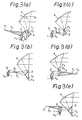
- a main reflector 4 is disposed on the upper side of a conical horn 1 and first and second subreflectors 2 and 3, as viewed therein.
- a phase center F0 of the conical horn 1 is one of focal points of the first subreflector 2.
- points F2 and F3 are focal points of the second subreflector 3 and a point F4 is that of the main reflector 4.
- reference characters N1, N2 and N indicate a point at which a beam emitted from the phase center of the conical horn 1 and propagated along a central axis of the conical horn 1 strikes on the first subreflector 2, a point at which the beam strikes on the second subreflector 3 and a point at which the beam strikes on the main reflector 4, respectively.
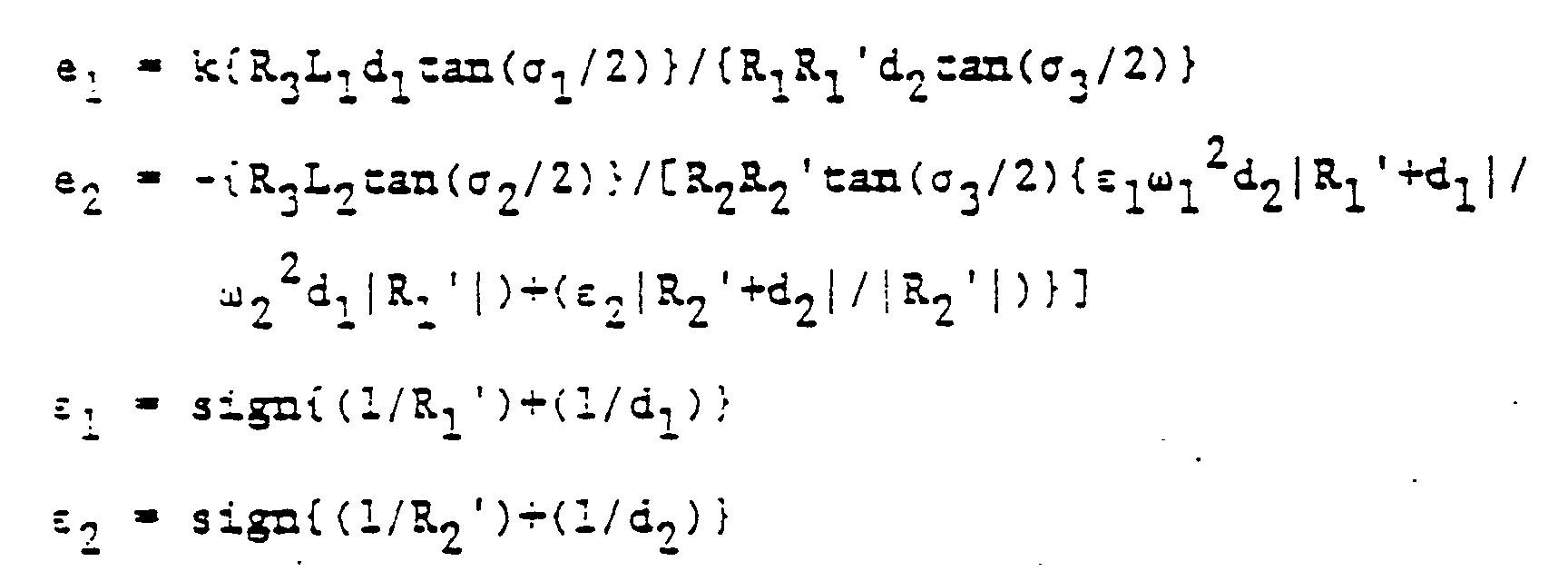
- ⁇ 1, ⁇ 2 and ⁇ 3 are angles formed by the incident wave to and the waves reflected from the first subreflector 2, the second subreflector 3 and the main reflector 4, respectively.
- L1 and L2 are a distance between the points F0 and F1 and that between the points F2 and F3.
- d1 and d2 are a distance between the points N1 and N2 and that between the points N2 and N, respectively.
- R1, R2 and R3 are radii of the curvatures of the wave surface of the incident ray or beam on the first and second subreflectors and main reflectors 2, 3 and 4, respectively.
- R1′ and R2′ are radii of the curvature of the wave surfaces of the beam reflected from the first and second subreflectors 2 and 3, respectively.
- these equations (1) and (2) can be essentially derived in the following way from an equation (17) described in the article (hereinunder referred to simply as Nakajima) entitled “4, 5, 6 GHz Band Offset Antenna Featuring Low Sidelobe and High Cross Polarization Discrimination” (by Nobuo Nakajima et al., Japan Denshi-Tsushin Gakkai Ronbunshi, vol., J67-B No. 2 (February, 1984), pp. 194-201) by using the results of study described in the article (hereinunder referred to simply as Mizusawa) entitled “Equalizing Parabolic Representation of Multiple Reflector Type Antenna and its Application” (by M. Mizusawa and T.
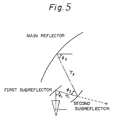
- the beam radii of the first and second subreflectors and main reflectors are denoted by ⁇ 1, ⁇ 2 and ⁇ 3 (corresponding to ⁇ 1, ⁇ 2, ⁇ 3) respectively.
- angles ⁇ 1, ⁇ 2 and ⁇ 3 are defined as shown in Fig. 5.
- the maximum magnitude C of the electric field of the cross-polarized component is obtained from the results of study described by using the results of study described in "Nakajima” [especially, equations (16) and (17); described therein] on the basis of the maximum value of the electric field of the primary polarized wave of the emitted pattern as follows:
- K i corresponds to ⁇ of equation (3).
- ⁇ denotes the wavelentgh of the beam in free space and ⁇ 1 and ⁇ 2 (corresponding to d1, d2) indicate a distance between the first and second subreflectors which is measured along the path of the central beam and a distance between the second subreflector and the main reflector which is also measured along the path of the central beam.
- equation (d2) can be modified by using the equation (d3) as follows:
- ⁇ 1 and D1 are obtained as functions of other parameters as follows:
- focal lengths ⁇ 1 and ⁇ 2 of the first and second subreflectors are derived from the equations (d5) and (d6) as follows:
- the corresponding subreflector is a concave mirror. Further, if negative, the corresponding subreflector is a convex mirror.
- the eccentricities e 1 and e 2 (each including its sign) of the first and second subreflectors are given by where L1 and L2 denote the distance between the focal points of the first subreflector and the distance between the focal points of the second subreflector, respectively.
- the parameter ⁇ (corresponding to ⁇ ) is + 1 in case the subreflector is a hyperboloidal reflector while - 1 in case a ellipsoidal reflector.
- the parameter ⁇ (corresponding to ⁇ i) is + 1 in case the subreflector is a concave mirror and is - 1 in case the subreflector is a convex mirror.
- the focal length ⁇ 3 of the main reflector can be approximately obtained by the following equations:
- equations (d11) are equivalent to the equations (1) and (2) under the condition expressed by the equation (d13).
- the derivation of the equations (1) and (2) are thus completed.
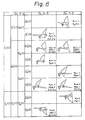
- Figs. 3(a) through (h) show an embodiment of the present invention corresponding to the combination of the parameters Pi and ⁇ i described in the leftmost column of Table 1.
- Figs 3(b) and (d) show embodiments of the invention corresponding to the second column from the left side of Table 1.
- Fig. 3(b) shows the configuration of the reflectors of the embodiment in case X1 > X2 while Fig. 3(d) shows that of the reflectors in case X1 ⁇ X2.
- Figs 3(c) and (e) show enbodiments corresponding to the third and fourth columns from the left side of Table 1, respectively. Further, Figs.
- FIG. 3(f) and (h) show embodiments corresponding to the fifth column from the left side of Table 1. Moreover, Fig. 3(f) shows the embodiment in case X1 ⁇ X2 while Fig. 3(h) shows that in case X1 > X2. Finally, Fig. 3(g) shows an embodiment corresponding to the rightmost column of Table 1.
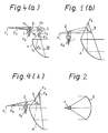
- FIG. 4(a) there is shown another embodiment in which a main reflector 4 is disposed on the lower side of a conical horn 1 and subreflectors 2 and 3.
- points F0, F1, F2, F3, N1, N2, N and W are defined in the same way as in Fig. 3(a).
- the eccentricity e1 should satisfy the following condition (1′).
- ⁇ 1, ⁇ 3, L1, d1, d2, R1 and R3 are defined in the same manner as in the description of the condition (1).
- ⁇ i is given by the above equation (3).
- the focal length f1 of the first subreflector is given by the following equation (4′).
- f1 - ⁇ f3 d1 tan( ⁇ 1/2) ⁇ / ⁇ d2 tan( ⁇ 3/2) ⁇
- focal point f2 of the second subreflector 3 is given by the above equation (5).
- Equation (6') is thus obtained from the equations (1′), (2), (4′) and (5) in place of the equation (6) above described.
- Figs. 4(a) and 4(b) Two examples of the antenna system according to the present invention corresponding to Table 2 are shown in Figs. 4(a) and 4(b).
- Fig. 4(a) shows an embodiment corresponding to the leftmost column of Table 2, that is, in case X1 ⁇ X2 while Fig. 4(b) shows that corresponding to the rightmost column of Table 2.
- the antenna system was assumed to use a conical horn as a primary radiator, the antenna system can be provided with any horn having a central axis as a primary radiator.
- each of the main and subreflectors of the antenna system is assumed to have a rotary quadratic surface
- the antenna system can be provided with what is called shaped reflectors as the main and subreflectors.
Landscapes
- Aerials With Secondary Devices (AREA)
- Variable-Direction Aerials And Aerial Arrays (AREA)
Claims (1)
le-dit système d'antenne étant construit de telle manière que l'excentricité (e1) du premier sous-réflecteur (2) et l'excentricité (e2) du second sous-réflecteur (3) sont respectivement exprimées comme suit:


Applications Claiming Priority (4)
| Application Number | Priority Date | Filing Date | Title |
|---|---|---|---|
| JP2413288 | 1988-02-04 | ||
| JP24132/88 | 1988-02-04 | ||
| JP24133/88 | 1988-02-04 | ||
| JP2413388 | 1988-02-04 |
Publications (2)
| Publication Number | Publication Date |
|---|---|
| EP0335077A1 EP0335077A1 (fr) | 1989-10-04 |
| EP0335077B1 true EP0335077B1 (fr) | 1991-09-18 |
Family
ID=26361617
Family Applications (1)
| Application Number | Title | Priority Date | Filing Date |
|---|---|---|---|
| EP89101694A Expired EP0335077B1 (fr) | 1988-02-04 | 1989-02-01 | Système d'antenne à trois réflecteurs avec suppression de polarisation croisée |
Country Status (5)
| Country | Link |
|---|---|
| US (1) | US5075692A (fr) |
| EP (1) | EP0335077B1 (fr) |
| JP (1) | JPH0720012B2 (fr) |
| DE (1) | DE68900266D1 (fr) |
| NO (1) | NO178449C (fr) |
Families Citing this family (3)
| Publication number | Priority date | Publication date | Assignee | Title |
|---|---|---|---|---|
| US5485168A (en) * | 1994-12-21 | 1996-01-16 | Electrospace Systems, Inc. | Multiband satellite communication antenna system with retractable subreflector |
| US5790077A (en) * | 1996-10-17 | 1998-08-04 | Space Systems/Loral, Inc. | Antenna geometry for shaped dual reflector antenna |
| JP2003277191A (ja) * | 2002-03-26 | 2003-10-02 | Japan Science & Technology Corp | Yb混晶酸化物単結晶からなるシンチレータ用発光材料 |
Family Cites Families (9)
| Publication number | Priority date | Publication date | Assignee | Title |
|---|---|---|---|---|
| US4109253A (en) * | 1977-02-22 | 1978-08-22 | Bell Telephone Laboratories, Incorporated | Method and apparatus for substantially reducing cross polarized radiation in offset reflector antennas |
| US4166276A (en) * | 1977-12-05 | 1979-08-28 | Bell Telephone Laboratories, Incorporated | Offset antenna having improved symmetry in the radiation pattern |
| US4298877A (en) * | 1979-01-26 | 1981-11-03 | Solar Energy Technology, Inc. | Offset-fed multi-beam tracking antenna system utilizing especially shaped reflector surfaces |
| JPS5991708A (ja) * | 1982-11-17 | 1984-05-26 | Mitsubishi Electric Corp | アンテナ装置 |
| JPS6128247A (ja) * | 1984-07-19 | 1986-02-07 | Nec Corp | 多方向マイクロ回線における同期伝送方式 |
| JPS6129570A (ja) * | 1984-07-20 | 1986-02-10 | Tokyo Electric Co Ltd | 紙送り装置 |
| JPS6129569A (ja) * | 1984-07-20 | 1986-02-10 | Tokyo Electric Co Ltd | 印字機の紙送り装置 |
| JP6129569B6 (ja) | 2013-02-04 | 2017-08-02 | 株式会社トーキン | 導電性高分子溶液及びその製造方法、導電性高分子材料並びに固体電解コンデンサ |
| JP6128247B2 (ja) | 2016-03-10 | 2017-05-17 | 信越化学工業株式会社 | 有機ケイ素化合物、並びにそれを用いたゴム用配合剤およびゴム組成物 |
-
1989
- 1989-02-01 EP EP89101694A patent/EP0335077B1/fr not_active Expired
- 1989-02-01 JP JP2349889A patent/JPH0720012B2/ja not_active Expired - Lifetime
- 1989-02-01 DE DE8989101694T patent/DE68900266D1/de not_active Expired - Lifetime
- 1989-02-02 NO NO890422A patent/NO178449C/no unknown
-
1991
- 1991-01-16 US US07/642,183 patent/US5075692A/en not_active Expired - Fee Related
Also Published As
| Publication number | Publication date |
|---|---|
| NO890422L (no) | 1989-08-07 |
| JPH0720012B2 (ja) | 1995-03-06 |
| NO890422D0 (no) | 1989-02-02 |
| US5075692A (en) | 1991-12-24 |
| NO178449B (no) | 1995-12-18 |
| NO178449C (no) | 1996-03-27 |
| DE68900266D1 (de) | 1991-10-24 |
| JPH0220902A (ja) | 1990-01-24 |
| EP0335077A1 (fr) | 1989-10-04 |
Similar Documents
| Publication | Publication Date | Title |
|---|---|---|
| US3828352A (en) | Antenna system employing toroidal reflectors | |
| Hasselmann et al. | Asymptotic analysis of parabolic reflector antennas | |
| US4223316A (en) | Antenna structure with relatively offset reflectors for electromagnetic detection and space telecommunication equipment | |
| Ashmead et al. | The use of spherical reflectors as microwave scanning aerials | |
| EP0335077A1 (fr) | Système d'antenne à trois réflecteurs avec suppression de polarisation croisée | |
| US4166276A (en) | Offset antenna having improved symmetry in the radiation pattern | |
| JPS603210A (ja) | 多周波帯域共用アンテナ | |
| US3112483A (en) | Wide angle scanning reflector | |
| RU2260230C1 (ru) | Антенна бортового радиолокатора | |
| JPH0221169B2 (fr) | ||
| Chu et al. | An experimental broadband imaging feed | |
| JP2822768B2 (ja) | アンテナ装置 | |
| Özdemir | Analysis of ring focus reflectors | |
| JPS60157302A (ja) | 複反射鏡アンテナ | |
| JP2712922B2 (ja) | 複反射鏡アンテナ | |
| JP2001156539A (ja) | アンテナ装置 | |
| Aoki et al. | A design method of an offset trireflector antenna whose main reflector is of an offset parabola type with high efficiency and low cross polarization characteristics | |
| JPS60157303A (ja) | 複反射鏡アンテナ | |
| JPS6128247B2 (fr) | ||
| SU951494A1 (ru) | Антенна СВЧ | |
| JPS6129569B2 (fr) | ||
| JP2001156540A (ja) | アンテナ装置 | |
| JPH01141405A (ja) | アンテナ装置 | |
| JP2001292022A (ja) | 四枚反射鏡形集束ビーム給電系 | |
| JP2001156541A (ja) | アンテナ装置 |
Legal Events
| Date | Code | Title | Description |
|---|---|---|---|
| PUAI | Public reference made under article 153(3) epc to a published international application that has entered the european phase |
Free format text: ORIGINAL CODE: 0009012 |
|
| AK | Designated contracting states |
Kind code of ref document: A1 Designated state(s): DE FR GB |
|
| 17P | Request for examination filed |
Effective date: 19891103 |
|
| 17Q | First examination report despatched |
Effective date: 19891211 |
|
| GRAA | (expected) grant |
Free format text: ORIGINAL CODE: 0009210 |
|
| AK | Designated contracting states |
Kind code of ref document: B1 Designated state(s): DE FR GB |
|
| REF | Corresponds to: |
Ref document number: 68900266 Country of ref document: DE Date of ref document: 19911024 |
|
| ET | Fr: translation filed | ||
| PLBE | No opposition filed within time limit |
Free format text: ORIGINAL CODE: 0009261 |
|
| STAA | Information on the status of an ep patent application or granted ep patent |
Free format text: STATUS: NO OPPOSITION FILED WITHIN TIME LIMIT |
|
| 26N | No opposition filed | ||
| REG | Reference to a national code |
Ref country code: GB Ref legal event code: 746 Effective date: 19951026 |
|
| REG | Reference to a national code |
Ref country code: FR Ref legal event code: D6 |
|
| PGFP | Annual fee paid to national office [announced via postgrant information from national office to epo] |
Ref country code: GB Payment date: 19990204 Year of fee payment: 11 |
|
| PGFP | Annual fee paid to national office [announced via postgrant information from national office to epo] |
Ref country code: DE Payment date: 19990205 Year of fee payment: 11 |
|
| PGFP | Annual fee paid to national office [announced via postgrant information from national office to epo] |
Ref country code: FR Payment date: 19990209 Year of fee payment: 11 |
|
| PG25 | Lapsed in a contracting state [announced via postgrant information from national office to epo] |
Ref country code: GB Free format text: LAPSE BECAUSE OF NON-PAYMENT OF DUE FEES Effective date: 20000201 |
|
| GBPC | Gb: european patent ceased through non-payment of renewal fee |
Effective date: 20000201 |
|
| PG25 | Lapsed in a contracting state [announced via postgrant information from national office to epo] |
Ref country code: FR Free format text: LAPSE BECAUSE OF NON-PAYMENT OF DUE FEES Effective date: 20001031 |
|
| PG25 | Lapsed in a contracting state [announced via postgrant information from national office to epo] |
Ref country code: DE Free format text: LAPSE BECAUSE OF NON-PAYMENT OF DUE FEES Effective date: 20001201 |
|
| REG | Reference to a national code |
Ref country code: FR Ref legal event code: ST |