EP0335162B1 - Procédé et dispositif de décontamination de couches du sol - Google Patents
Procédé et dispositif de décontamination de couches du sol Download PDFInfo
- Publication number
- EP0335162B1 EP0335162B1 EP89104468A EP89104468A EP0335162B1 EP 0335162 B1 EP0335162 B1 EP 0335162B1 EP 89104468 A EP89104468 A EP 89104468A EP 89104468 A EP89104468 A EP 89104468A EP 0335162 B1 EP0335162 B1 EP 0335162B1
- Authority
- EP
- European Patent Office
- Prior art keywords
- chamber
- tube
- soil
- chambers
- borehole
- Prior art date
- Legal status (The legal status is an assumption and is not a legal conclusion. Google has not performed a legal analysis and makes no representation as to the accuracy of the status listed.)
- Expired - Lifetime
Links
- 239000002689 soil Substances 0.000 title claims description 62
- 238000000034 method Methods 0.000 title claims description 49
- 239000003344 environmental pollutant Substances 0.000 claims description 21
- 231100000719 pollutant Toxicity 0.000 claims description 21
- 239000002245 particle Substances 0.000 claims description 10
- 239000010802 sludge Substances 0.000 claims description 8
- 239000000203 mixture Substances 0.000 claims description 7
- 230000008878 coupling Effects 0.000 claims description 6
- 238000010168 coupling process Methods 0.000 claims description 6
- 238000005859 coupling reaction Methods 0.000 claims description 6
- 239000003673 groundwater Substances 0.000 claims description 6
- 239000011230 binding agent Substances 0.000 claims description 2
- 239000000126 substance Substances 0.000 claims description 2
- 238000000746 purification Methods 0.000 claims 7
- 238000003780 insertion Methods 0.000 claims 1
- 230000037431 insertion Effects 0.000 claims 1
- 238000011403 purification operation Methods 0.000 claims 1
- 239000012629 purifying agent Substances 0.000 claims 1
- XLYOFNOQVPJJNP-UHFFFAOYSA-N water Substances O XLYOFNOQVPJJNP-UHFFFAOYSA-N 0.000 claims 1
- 238000004140 cleaning Methods 0.000 description 68
- 230000008569 process Effects 0.000 description 17
- 239000007787 solid Substances 0.000 description 7
- 230000000694 effects Effects 0.000 description 5
- 230000009471 action Effects 0.000 description 3
- 230000008901 benefit Effects 0.000 description 3
- 125000006850 spacer group Chemical group 0.000 description 3
- 239000012459 cleaning agent Substances 0.000 description 2
- 239000003795 chemical substances by application Substances 0.000 description 1
- 238000010276 construction Methods 0.000 description 1
- 239000000356 contaminant Substances 0.000 description 1
- 239000003599 detergent Substances 0.000 description 1
- 238000010586 diagram Methods 0.000 description 1
- 238000006073 displacement reaction Methods 0.000 description 1
- 238000005553 drilling Methods 0.000 description 1
- 238000003912 environmental pollution Methods 0.000 description 1
- 238000000605 extraction Methods 0.000 description 1
- 230000035515 penetration Effects 0.000 description 1
- 230000000704 physical effect Effects 0.000 description 1
- 230000002250 progressing effect Effects 0.000 description 1
- 230000000750 progressive effect Effects 0.000 description 1
- 230000009467 reduction Effects 0.000 description 1
- 238000000638 solvent extraction Methods 0.000 description 1
Images




Classifications
-
- B—PERFORMING OPERATIONS; TRANSPORTING
- B09—DISPOSAL OF SOLID WASTE; RECLAMATION OF CONTAMINATED SOIL
- B09C—RECLAMATION OF CONTAMINATED SOIL
- B09C1/00—Reclamation of contaminated soil
- B09C1/02—Extraction using liquids, e.g. washing, leaching, flotation
-
- E—FIXED CONSTRUCTIONS
- E21—EARTH OR ROCK DRILLING; MINING
- E21B—EARTH OR ROCK DRILLING; OBTAINING OIL, GAS, WATER, SOLUBLE OR MELTABLE MATERIALS OR A SLURRY OF MINERALS FROM WELLS
- E21B37/00—Methods or apparatus for cleaning boreholes or wells
-
- E—FIXED CONSTRUCTIONS
- E21—EARTH OR ROCK DRILLING; MINING
- E21B—EARTH OR ROCK DRILLING; OBTAINING OIL, GAS, WATER, SOLUBLE OR MELTABLE MATERIALS OR A SLURRY OF MINERALS FROM WELLS
- E21B41/00—Equipment or details not covered by groups E21B15/00 - E21B40/00
- E21B41/0078—Nozzles used in boreholes
Definitions
- the invention relates to a method for cleaning contaminated soil layers, in which the pollutants are separated in place from the loosened soil particles with a cleaning medium introduced into the soil layers under high pressure and discharged with the cleaning medium returned to the soil surface.
- a cleaning medium introduced into the soil layers under high pressure and discharged with the cleaning medium returned to the soil surface.
- the invention further relates to a device for cleaning pollutant-containing soil layers by means of a cleaning medium which is introduced into the soil layers through a drill pipe and which absorbs the pollutants and which may be suctioned off from the soil layers together with soil particles and subsequently processed, the drill pipe at its lower end having a drill bit and has an outlet nozzle located slightly above for the cleaning medium under high pressure.
- a method described in DE-U-8,804,344 (filing date: March 31, 2008) for cleaning contaminated soil layers uses a drill pipe which consists of a core tube leading the cleaning medium into the soil layers and a jacket tube surrounding the core tube. At its lower end, the core tube is provided with a drill bit, above which there is an outlet nozzle for the cleaning medium, which is under high pressure.
- the jacket tube is sealed above the outlet nozzle with respect to the core tube and has a suction opening for the polluting cleaning medium in the region of its lower end.
- the pollutant-laden cleaning medium returns to the earth's surface under the action of a suction pump via an annular space formed between the casing tube and the core tube, where it is fed to a treatment facility.
- the floor cleaning method which can be carried out with the known device is carried out either when lowering or extending the rotating drill pipe.
- the cleaning medium supplied via the core tube leaves the outlet nozzle under high pressure and penetrates horizontally as a cutting jet into the floor layer to be cleaned. In this way, the grains of the soil are hosed down and pollutants are removed. Due to the progressive axial movement of the drill pipe, the floor layers soaked with cleaning medium subsequently reach the effective area of the suction opening of the casing pipe, are conveyed from there to the surface of the earth and then processed.
- a disadvantage of the method of DE-U-8,804,344 is that the soil column detected by the cleaning process can have a different diameter, since depending on the structure of the soil layer, the depth of penetration of the cutting jet and the size of the area cleaned around the drill pipe vary. This can have an undesirable influence on already cleaned or pollutant-free floor areas.
- the invention has for its object to provide a method for cleaning contaminated soil layers, which allows a targeted definition of the floor area affected by the respective cleaning process and ensures an overview of the course of the boundary between contaminated and cleaned floor areas at all times, and a suitable device therefor .
- the cleaning process proceeding in the vertical direction is carried out in each case within a tubular chamber which is introduced into the floor and is introduced into the soil offset in the horizontal direction for the progress of the cleaning.
- the method according to the invention has the advantage of enabling the user to precisely determine the course of the boundary between contaminated and cleaned floor areas, so that a targeted determination of the floor areas still to be cleaned can be carried out.
- the cleaning medium loaded with pollutants gets into adjacent, already cleaned or pollutant-free areas.
- At least parts of the chamber used for this purpose are removed from the floor and placed in a region of the floor which has not yet been cleaned after the respective cleaning process has ended. It is particularly advantageous to move the chambers or parts of the chambers so that the chambers form a horizontally progressing honeycomb pattern. When using this "wandering" working method, larger areas can also be systematically cleaned, whereby the course of the boundary between contaminated and cleaned floor areas is clearly defined at all times.
- a technical solution to the problem is proposed in a chamber which is open at the bottom and surrounds the drill pipe and projects at least to the depth of the drill bit into the bottom layers.
- the chamber can be formed by a cylindrical tube or can be composed of a plurality of vertically extending shells, as a result of which the chamber can be designed in particular in the form of a polygon.
- connection of the shells to one another can be achieved by coupling pieces which can be pushed into one another, as a result of which the partitioning against the escape of contaminated cleaning medium is additionally improved.
- the drill pipe can be either axially immovable or displaceable relative to the chamber. If the drill pipe is displaceable relative to the chamber, it is advantageous to provide a radial guide for the drill pipe in the region of the chamber and in this way to ensure the centering of the drill pipe.
- the top of the chamber is closed in a pressure-tight manner and is provided with a connection to a pressure pump. In this way, the inflow of the cleaning medium to the suction opening is supported with simple technical means.
- the invention also proposes that the drill pipe is composed of a core pipe having the drill bit and the outlet nozzle and a jacket pipe surrounding the core pipe, which is sealed above the outlet nozzle from the core pipe and in the region of its lower end with at least one suction opening for the pollutant-laden Cleaning medium and is provided at its upper end with a drain opening for the polluted cleaning medium conveyed to the earth's surface in the annular space between the core tube and the jacket tube.
- the suction port of a suction pump is connected to the drain opening of the casing tube.
- the suction pump is mainly used when the pollutant-laden cleaning medium is sucked out from not too great depths.
- the suction opening is provided with a cylindrical sieve surrounding the core tube. This ensures that only the cleaning medium loaded with pollutants, but not parts of the floor, are suctioned off.
- a sludge mixture within the chamber cannot be separated into soil and pollutant / detergent mixture. Therefore, according to a further embodiment, it is provided to additionally arrange a solids pump within the chamber, with which a sludge mixture of soil particles, pollutants and cleaning agents can also be safely conveyed from greater depths.
- the delivery rate of the solids pump is controlled so that the open groundwater level within the chamber does not fall below a predetermined low level, in order to avoid a hydraulic break at the foot of the chamber.
- the sludge mixture is processed in a cleaning system and the cleaned soil particles are reinstalled in the chamber, the soil inside the chamber being either mechanically compacted and / or optimized by adding binders and / or adding other substances, depending on requirements .
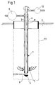
- the device shown in FIG. 1 for cleaning deep-lying, contaminant-containing soil layers projects with a drill pipe 1 into the floor 2 to be cleaned.
- the drill pipe 1 consists primarily of a core pipe 3 and a jacket pipe 4 surrounding it.
- the core pipe 3 and the casing tube 4 is sealed against one another at its lower end, the end face of the core tube 3 protruding from the casing tube 4 being provided with a drill bit 5 which bears against the core tube 3 with the interposition of a spacer 5a.
- the core tube 3 has at least one lateral outlet nozzle 6.
- a suction opening 7 above the outlet nozzle 6 is connected via an annular space 8 formed between the core tube 3 and the casing tube 4 to a suction pump 9, which in turn is connected to a treatment device (not shown).
- the drill pipe 1 can be rotated and subjected to an axial force via a device, not shown, so that the drill pipe can be driven axially into the ground.
- the displacement of the soil takes place through the drill bit 5 provided with corresponding work surfaces.
- cleaning medium is conveyed into the interior of the core tube 3, from where the cleaning medium under high pressure drop, but at high speed penetrates through the outlet nozzle 6 into the respective soil layer.
- the strongly bundled cleaning medium flows around the soil grains and removes the pollutants in the floor.
- Due to the very high pressure in the core tube 3, the effect of the emerging cleaning medium is similar to that of a cutting jet, which additionally loosens the applied layers of soil.
- the diameter of the floor column 11 depends on the range of the cutting beam, which in turn is influenced by the nature of the floor.
- the cleaning medium already loaded with rinsed pollutants is sucked off via the suction opening 7.
- This is preferably done in such a way that when the drill pipe 1 is rotated into the ground, the respective floor layers are first soaked by the cutting jet emerging from the outlet nozzle 6 and, after the corresponding floor layers come into the effective range of the suction opening 7, the loaded cleaning medium is drawn off by the action of the suction pump 9 and fed to a subsequent treatment.
- the distance between the suction opening 7 and the outlet nozzle 6 can be adjusted by appropriately selecting the thickness of the spacer 5a.
- the suction opening 7 is provided with a cylindrical sieve 12 which surrounds the core tube 3 and which prevents soil particles from being sucked out of the soil layer surrounding the sieve 12.
- a cylindrical sieve 12 which surrounds the core tube 3 and which prevents soil particles from being sucked out of the soil layer surrounding the sieve 12.
- an edge 13 is formed on the lower end face of the casing tube 4, which cleans with a relative movement between the casing tube 4 and the core tube 3 cleaning over the outer jacket surface 14 of the screen 12 firmly connected to the core tube 3 in the exemplary embodiment and this freed from unwanted deposits.
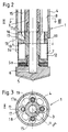
- FIGS. 2 and 3 there is at least one pressure line 15 in the annular space 8 between the casing tube 4 and the core tube 3.
- the mouth 16 of the pressure line 15 is located somewhat above the suction opening 7 and is directed towards the bottom 17 of a blind hole 17a, so that incoming compressed air is deflected via the pressure line 15 and flows again via the annular space 8 to the upper end of the drill pipe 1.
- the blind hole 17a is located in the top of an annular flange 18 which is connected to the core tube 3 and axially pierced by through openings 19.
- the blind holes 17a of the ring flange 18 are in each case an extension of the pressure lines 15, while the passage openings 19 are arranged in between.
- gas flowing in under pressure in particular compressed air
- the pressure lines 15 at the bottom 17 by 180 ° and is returned to the upper end of the drill pipe 1 by creating a negative pressure next to the passage openings 19.
- the cross-sectional area of the free annular space 8 is larger than the total cross-sectional area of the pressure lines 15, a negative pressure is created in the area of the suction openings 7.
- This suction effect is used in order to generate the vacuum necessary for suction of the cleaning medium laden with pollutants without the suction pump 9 shown in FIG. 1.
- This last-mentioned possibility of returning the cleaning medium is to be used above all if a suction pump can no longer be used due to the large suction head.
- the drill pipe 1 is guided within a chamber 20 which is embedded in the bottom and is designed as a cylindrical pipe.
- the chamber 20 is sealed on its upper side by a cover 21, a centrally arranged opening 22 in the cover 21 guiding the drill pipe 1 radially.
- the chamber 20 is lowered so far into the bottom 2 that its lower edge is lower than the outlet nozzle 6 of the drill pipe 1 in its lowest working position.
- the chamber 20 and the drill pipe 1 are arranged to be axially displaceable with respect to one another.
- the chamber 20 is introduced vertically into the base 2, which can be accomplished, for example, with the aid of appropriate hydraulic devices. The cleaning process already described then begins when the drill pipe 1 is retracted.
- the lid 21 of the chamber 20 is connected via a pressure connection 23a to a pressure pump 23b, preferably for generating compressed air, so that a pressure cushion is generated on the surface of the bottom enclosed by the chamber 20 to support the suction effect of the suction opening 7.
- the inner diameter of the chamber 20 should be matched to the strength of the cleaning medium emerging in the form of a cutting jet from the outlet nozzle 6, whereby it must be ensured that the cutting jet safely reaches the inner wall of the chamber 20 so that the entire inside the chamber 20 Soil layers are washed through.
- the size of the suction effect via the suction opening 7 should also be coordinated so that a safe suction of loaded cleaning medium is also ensured from the areas of the chamber 20 close to the wall.
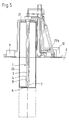
- the embodiment of the invention shown in FIG. 5 differs from the embodiment shown in FIG. 4 by the axially immovable arrangement of drill pipe 1 and chamber 20 relative to one another.
- the drill pipe 1 and the chamber 20 are thus simultaneously introduced into the base 2. This can be done either by screwing in both parts at the same time or by ramming the chamber 20 while taking the rotating drill pipe 1 with it.
- the actual cleaning process can be carried out both when lowering and when catching up the chamber 20 and the drill pipe 1.
- the method for cleaning contaminated soil layers is advantageously carried out according to the flow diagram shown in three stages in FIG. 6.
- FIG. 6 In the upper part of FIG. 6 it can be seen how the cleaning process has already been completed in the hatched row of chambers 20a, while almost two further rows of unshaded chambers 20b have already been lowered into the floor without the cleaning process having already started . Chambers still to be set in central axes are identified in FIG. 6 by a small cross.
- the chambers do not have to be designed as cylindrical tubes, but they can also have the shape of polygons, which are composed of several shells 24 inserted vertically into the floor. From Fig. 7 it can be seen that a chamber having the cross section of a hexagon can be composed of four shells 24 each, these shells 24 having the shape of a trapezoid open on its long side.
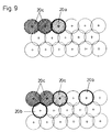
- FIG. 9 shows that the individual tubular chambers can also be arranged such that the areas to be cleaned overlap.
- the cleaning process has already been completed in the double hatched chambers 20c and the chamber tube has been removed again, whereas cleaning is carried out in the chamber tube 20a shown next to it.
- the center axes of the chambers to be placed are marked with a small cross, the outlines of the chambers are indicated with a thinner line width.
- the entire cleaning process is carried out only with a tubular chamber tube, which is implemented in each case.
- FIG. 9 it is shown schematically that two or more chamber pipes can be in use at the same time, the places of use being chosen so that the areas to be cleaned can overlap to a predetermined extent.
- a solids pump 27 with a delivery line 28 is arranged, which can be controlled in such a way that the delivery rate of the solids pump 27 only conveys so much sludge mixture of soil particles, pollutants and cleaning agents that within the chamber 20 existing groundwater level 31 can not drop below a predetermined low level.
- the solids pump 27 conveys the sludge mixture into the above-ground cleaning system 29 through the delivery line 28.
Landscapes
- Life Sciences & Earth Sciences (AREA)
- Engineering & Computer Science (AREA)
- Geology (AREA)
- Mining & Mineral Resources (AREA)
- Environmental & Geological Engineering (AREA)
- Physics & Mathematics (AREA)
- Fluid Mechanics (AREA)
- General Life Sciences & Earth Sciences (AREA)
- Geochemistry & Mineralogy (AREA)
- Soil Sciences (AREA)
- Processing Of Solid Wastes (AREA)
- Earth Drilling (AREA)
Claims (29)
- Procédé de décontamination de couches du sol renfermant des substances nocives, selon lequel, à l'aide d'un agent de décontamination introduit sous une pression élevée dans les couches du sol, les substances nocives sont séparées sur place des particules de sol ameublies, et sont évacuées avec l'agent de décontamination ramené à la surface du sol,
caractérisé en ce que l'opération de décontamination qui progresse en direction verticale, s'effectue respectivement à l'intérieur d'une chambre (20) de forme tubulaire qui a été introduite dans le sol, et qui pour la progression de la décontamination est introduite dans le terrain en étant décalée en direction horizontale. - Procédé selon la revendication 1, caractérisé en ce qu'après l'achèvement de chaque opération de décontamination, au moins des parties des chambres (20) utilisées à cet effet, sont extraites du sol (2) et sont décalées vers une zone du sol (2) n'ayant pas encore été décontaminée.
- Procédé selon la revendication 2, caractérisé en ce que les chambres (20) ou des parties des chambres (20) sont décalées de telle sorte que les chambres (20) forment un motif en nid d'abeilles progressant en direction horizontale.
- Procédé selon la revendication 3, caractérisé en ce que les chambres (20) ou des parties des chambres (20) sont décalées de telle sorte que les zones décontaminées et non décontaminées du sol (2), sont séparées les unes des autres.
- Procédé selon la revendication 1, caractérisé en ce que la chambre (20) est introduite dans les couches du sol, en même temps qu'un tube de forage (1) conduisant l'agent de décontamination.
- Procédé selon la revendication 1, caractérisé en ce que les chambres de forme tubulaire introduites dans le sol, sont disposées successivement de manière à ce que les zones à décontaminer se chevauchent.
- Procédé selon les revendications 1 et 6, caractérisé en ce que l'on travaille uniquement avec un seul tube de chambre, et en ce que le tube de chambre, après l'opération de décontamination, est à nouveau réintroduit dans le terrain après avoir été décalé en direction horizontale.
- Procédé selon les revendications 1 et 6, caractérisé en ce que l'on travaille avec deux ou plusieurs tubes de chambre, la mise en place des tubes de chambre, la décontamination du sol et l'extraction des tubes de chambre s'effectuant de manière séparée.
- Procédé selon la revendication 1, caractérisé en ce que pour l'extraction d'un mélange de boues renfermant, mis à part les substances nocives et l'agent de décontamination, également des particules de sol, on utilise une pompe à substances solides, qui refoule le mélange de boues au travers d'une conduite de refoulement, vers une installation de décontamination.
- Procédé selon la revendication 9, caractérisé en ce que le débit de la pompe à substances solides est commandé de manière à ce que le niveau des eaux souterraines dans la chambre, ne passe pas endessous d'une profondeur prédéfinie.
- Procédé selon la revendication 9 ou 10, caractérisé en ce que pour commander le niveau des eaux souterraines dans la chambre, de l'eau est envoyée en supplément dans la chambre, par le haut.
- Procédé selon la revendication 9 ou 11, caractérisé en ce que dans l'installation de décontamination, des particules de sol décontaminées sont séparées du mélange de boues et sont à nouveau réintroduites dans la chambre.
- Procédé selon l'une des revendications 1 et 9 à 12, caractérisé en ce que suivant les besoins, le sol décontaminé est comprimé mécaniquement à l'intérieur de la chambre.
- Procédé selon l'une des revendications 1 et 9 à 13, caractérisé en ce que le sol décontaminé est optimisé par l'addition de liant.
- Procédé selon l'une des revendications 1 et 9 à 14, caractérisé en ce le sol décontaminé est optimisé par l'addition d'autres substances.
- Dispositif pour la décontamination de couches du sol renfermant des substances nocives, au moyen d'un agent de décontamination qui absorbe les substances nocives et est introduit dans les couches du sol à l'aide d'un tube de forage (1), et qui est aspiré hors des couches du sol et ensuite traité, le tube de forage (1) comportant à son extrémité inférieure, une couronne de forage (5) et, disposée légèrement au-dessus de celui-ci, une buse de sortie (6) pour l'agent de décontamination se trouvant sous forte pression, notamment pour la mise en oeuvre du procédé selon les revendications 1 à 5,
caractérisé par une chambre (20), ouverte vers le bas, entourant le tube de forage (1) et s'engageant dans les couches du sol au moins jusqu'à la profondeur du trépan de forage (5). - Dispositif selon la revendication 16, caractérisé en ce que la chambre (20) est réalisée sous la forme d'un tube cylindrique.
- Dispositif selon la revendication 16, caractérisé en ce que la chambre (20) est réalisée par l'assemblage de plusieurs coques (24) s'étendant verticalement.
- Dispositif selon la revendication 17 ou 18, caractérisé en ce que la chambre (20) présente en section droite, une forme de polygone.
- Dispositif selon la revendication 18, caractérisé en ce que les coques (24) sont reliées entre-elles par l'intermédiaire de pièces d'accouplement (25, 26) pouvant être emboîtées l'une dans l'autre par coulissement.
- Dispositif selon la revendication 16, caractérisé en ce que le tube de forage (1) est réalisé de manière à ne pas pouvoir coulisser axialement par rapport à la chambre (20).
- Dispositif selon la revendication 16, caractérisé en ce que le tube de forage (1) est réalisé de manière à pouvoir coulisser axialement par rapport à la chambre (20).
- Dispositif selon la revendication 22, caractérisé par un guidage radial pour le tube de forage (1) dans la zone supérieure de la chambre (20).
- Dispositif selon la revendication 23, caractérisé en ce que la chambre (20) est fermée de manière étanche à la pression, sur son côté supérieur, au moyen d'un couvercle (21), et est raccordée à une pompe refoulante (23b) à l'aide d'un raccord de pression (23a).
- Dispositif selon la revendication 16, caractérisé en ce que le tube de forage (1) est constitué d'un tube central (3) portant la couronne de forage (5) ainsi que la buse de sortie (6), et d'un tube-enveloppe (4) qui entoure le tube central (3), qui, au-dessus de la buse de sortie (6) est rendu étanche par rapport au tube central (3), qui au niveau de son extrémité inférieure, est pourvu d'au moins un orifice d'aspiration (7) pour l'agent de décontamination chargé en substances nocives, et qui à son extrémité supérieure est pourvu d'un orifice d'évacuation pour l'agent de décontamination chargé en substances nocives, ayant été transporté jusqu'à la surface du sol dans l'espace annulaire (8) entre le tube central (3) et le tube-enveloppe (4).
- Dispositif selon la revendication 25, caractérisé en ce qu'à l'orifice d'évacuation du tube-enveloppe (4) est branché le raccord d'aspiration d'une pompe aspirante (9).
- Dispositif selon la revendication 25, caractérisé en ce que dans le tube de forage (1) est disposée au moins une conduite sous pression (15) qui débouche, au-dessus de l'orifice d'aspiration (7), dans l'espace annulaire (8) entre le tube central (3) et le tube-enveloppe (4).
- Dispositif selon l'une des revendications 25 à 27, caractérisé en ce que l'orifice d'aspiration (7) est muni d'un tamis cylindrique (12) entourant le tube central (3).
- Dispositif selon la revendication 28, caractérisé en ce que le tamis (12) est fixé sur le tube central (3) ou sur le tube-enveloppe (4) et qu'un bord de l'autre tube respectif (4, 3) peut être guidé au-dessus de la surface extérieure du tamis (12) en vue de la nettoyer, par suite d'un mouvement relatif entre les tubes (3, 4).
Priority Applications (1)
| Application Number | Priority Date | Filing Date | Title |
|---|---|---|---|
| AT89104468T ATE81601T1 (de) | 1988-03-31 | 1989-03-14 | Verfahren sowie vorrichtung zur reinigung von bodenschichten. |
Applications Claiming Priority (4)
| Application Number | Priority Date | Filing Date | Title |
|---|---|---|---|
| DE3810941 | 1988-03-31 | ||
| DE3810941 | 1988-03-31 | ||
| DE3843836A DE3843836A1 (de) | 1988-03-31 | 1988-12-24 | Verfahren sowie vorrichtung zur reinigung von bodenschichten |
| DE3843836 | 1988-12-24 |
Publications (3)
| Publication Number | Publication Date |
|---|---|
| EP0335162A2 EP0335162A2 (fr) | 1989-10-04 |
| EP0335162A3 EP0335162A3 (en) | 1990-08-08 |
| EP0335162B1 true EP0335162B1 (fr) | 1992-10-21 |
Family
ID=25866578
Family Applications (1)
| Application Number | Title | Priority Date | Filing Date |
|---|---|---|---|
| EP89104468A Expired - Lifetime EP0335162B1 (fr) | 1988-03-31 | 1989-03-14 | Procédé et dispositif de décontamination de couches du sol |
Country Status (5)
| Country | Link |
|---|---|
| US (1) | US5069725A (fr) |
| EP (1) | EP0335162B1 (fr) |
| DE (2) | DE3843836A1 (fr) |
| DK (1) | DK156889A (fr) |
| ES (1) | ES2035398T3 (fr) |
Cited By (1)
| Publication number | Priority date | Publication date | Assignee | Title |
|---|---|---|---|---|
| DE102015108704B4 (de) | 2015-06-02 | 2019-05-02 | Henning & Quade Berlin GmbH & Co. KG | Spüllanze |
Families Citing this family (13)
| Publication number | Priority date | Publication date | Assignee | Title |
|---|---|---|---|---|
| DE4003362A1 (de) * | 1990-02-05 | 1991-08-08 | Keller Grundbau Gmbh | Verfahren und vorrichtung zur in-situ-sanierung kontaminierter bereiche |
| FR2678021B1 (fr) * | 1991-06-21 | 1999-01-15 | Inst Francais Du Petrole | Appareil et installation pour le nettoyage de drains, notamment dans un puits de production petroliere. |
| US5855668A (en) * | 1994-03-25 | 1999-01-05 | Kabushiki Kaisha Shinkosha | Surface treating method of single crystal |
| US5535836A (en) * | 1994-05-25 | 1996-07-16 | Ventura Petroleum Services , Inc. | Total recovery drill |
| DE19836240C2 (de) * | 1997-08-07 | 2002-01-10 | Wilko Werner | Verfahren zur on-site Reinigung von schadstoffhaltigen Bodenschichten in Grundwasser führenden Bodenformationen |
| DE19753305A1 (de) * | 1997-12-02 | 1998-05-14 | Emil Dipl Ing Gansloser | Verfahren zum Sanieren von Umweltschäden |
| US20040020001A1 (en) * | 2002-06-03 | 2004-02-05 | Lorincz Thomas A. | Apparatus and method for washing the inside of wine barrels |
| US20090080979A1 (en) * | 2007-09-21 | 2009-03-26 | Fruits & Associates, Inc. | System and method for decontaminating soil and groundwater |
| CN103639083B (zh) * | 2013-12-26 | 2016-04-06 | 江苏盖亚环境工程有限公司 | 一种污染土壤喷淋修复系统 |
| EP3106238A1 (fr) * | 2015-06-19 | 2016-12-21 | CDM Smith Consult GmbH | Procédé d'assainissement de zones contaminées comme des dépôts anciens ou décharges |
| CN107096349B (zh) * | 2017-06-28 | 2022-12-30 | 陕西澄合山阳煤矿有限公司 | 一种煤矿用密集浅孔捕尘器 |
| FR3100142B1 (fr) | 2019-08-28 | 2021-11-05 | Rmv Equipement | Dispositif d’extraction et de décontamination de substances organiques et/ou inorganiques à partir de matières solides ou semi-solides sous le contrôle de plusieurs paramètres |
| EP4537947A1 (fr) * | 2023-10-13 | 2025-04-16 | Hilti Aktiengesellschaft | Buse combinée de pulvérisation et d'aspiration pour un dispositif de fourniture d'eau, procédé de nettoyage d'un puits de forage et produit programme informatique |
Family Cites Families (7)
| Publication number | Priority date | Publication date | Assignee | Title |
|---|---|---|---|---|
| US2239586A (en) * | 1940-02-29 | 1941-04-22 | Peter W Appleby | Well washing apparatus |
| US3432348A (en) * | 1966-11-28 | 1969-03-11 | Battelle Development Corp | Fluid distributor for vertical vessels |
| DE2047684C3 (de) * | 1970-09-28 | 1980-09-04 | Texaco Trinidad Inc., New York, N.Y. (V.St.A.) | Verfahren zur Behandlung von asphaltische Ablagerungen enthaltenden Bohrungen und Formationen |
| US4447541A (en) * | 1983-06-06 | 1984-05-08 | Galson Research Corporation | Methods for decontaminating soil |
| US4582611A (en) * | 1984-08-09 | 1986-04-15 | Brian Watt Associates, Inc. | Soil decontamination with wick drains |
| AU4809685A (en) * | 1984-09-04 | 1986-03-24 | Manchak, F. | In situ waste impoundment treating apparatus and method of using same |
| DE8804344U1 (de) * | 1988-03-31 | 1988-06-09 | Philipp Holzmann Ag, 6000 Frankfurt | Vorrichtung zur Reinigung von Bodenschichten |
-
1988
- 1988-12-24 DE DE3843836A patent/DE3843836A1/de active Granted
-
1989
- 1989-03-14 ES ES198989104468T patent/ES2035398T3/es not_active Expired - Lifetime
- 1989-03-14 EP EP89104468A patent/EP0335162B1/fr not_active Expired - Lifetime
- 1989-03-14 DE DE8989104468T patent/DE58902477D1/de not_active Expired - Fee Related
- 1989-03-31 US US07/332,260 patent/US5069725A/en not_active Expired - Lifetime
- 1989-03-31 DK DK156889A patent/DK156889A/da not_active Application Discontinuation
Cited By (1)
| Publication number | Priority date | Publication date | Assignee | Title |
|---|---|---|---|---|
| DE102015108704B4 (de) | 2015-06-02 | 2019-05-02 | Henning & Quade Berlin GmbH & Co. KG | Spüllanze |
Also Published As
| Publication number | Publication date |
|---|---|
| DE3843836C2 (fr) | 1990-07-26 |
| DE3843836A1 (de) | 1989-10-12 |
| DK156889D0 (da) | 1989-03-31 |
| EP0335162A3 (en) | 1990-08-08 |
| US5069725A (en) | 1991-12-03 |
| DK156889A (da) | 1989-10-01 |
| DE58902477D1 (de) | 1992-11-26 |
| ES2035398T3 (es) | 1993-04-16 |
| EP0335162A2 (fr) | 1989-10-04 |
Similar Documents
| Publication | Publication Date | Title |
|---|---|---|
| EP2998037B1 (fr) | Dispositif destiné au nettoyage d'une semelle d'un trou de forage et procédé de création d'un élément de fondation | |
| DE19737831C2 (de) | Verfahren zur Ausbildung einer Kiespackung in einem Bohrloch | |
| DE69412497T2 (de) | Verfahren und vorrichtung zum bohren eines horizontalen loches | |
| DE3843836C2 (fr) | ||
| DE3874695T2 (de) | Verfahren und vorrichtung zum entfernen von alten pfaehlen. | |
| DE9007432U1 (de) | Brunnenregeneriergerät | |
| DE8804344U1 (de) | Vorrichtung zur Reinigung von Bodenschichten | |
| DE3108331C2 (de) | Verfahren und Vorrichtung zur Ausbildung eines Gesteinsfilters in einem der Grundwassergewinnung oder -absenkung dienenden Bohrbrunnen | |
| DE4217184A1 (de) | Verfahren zum Ausbringen von Ölresten oder ölhaltigen Flüssigkeiten aus verseuchten Bodenschichten | |
| WO2009052791A2 (fr) | Dispositif et procédé d'activation ou de nettoyage de puits | |
| DE3844689C2 (en) | Cleaning contaminated ground in successive vertical operations | |
| DE102008055623B4 (de) | Vorrichtung und Verfahren zum Aktivieren oder Reinigen von Brunnen | |
| DE3920800C1 (en) | Detoxifying soil in-situ - by introducing cleansing medium and vibrating using cylindrical chamber with 3 radial plate carrying tubes | |
| DE2807917A1 (de) | Verfahren und vorrichtung zum reinigen der bei erdaushubarbeiten verwendeten fluessigkeiten | |
| EP0562301B1 (fr) | Méthode de configuration des puits d'eau | |
| WO2005007980A1 (fr) | Puits, et procede de regeneration d'un puits | |
| DE3904328C1 (en) | Method and apparatus for cleaning soil layers | |
| EP3643872B1 (fr) | Procédé de réduction de la porosité hydrauliquement active d'une matrice solide poreuse | |
| DE3034746C2 (de) | Verfahren und Vorrichtung zum Herstellen von Grundwasserdurchlässen in Dichtungswänden | |
| EP3061875B1 (fr) | Dispositif et procede d'activation ou de nettoyage de puits | |
| DE102022109822A1 (de) | Verfahren und Vorrichtung zur Regenerierung eines Versickerungsbrunnens in einem ungesättigten porösen Medium | |
| DE102007009037A1 (de) | Horizontalfilterbrunnen | |
| DE10258963B4 (de) | Vorrichtung zum Spülbohren von Bohrlöchern in Böden | |
| EP0982470A2 (fr) | Methode pour construire un puits | |
| WO2000035812A2 (fr) | Procede et reacteur pour la decontamination d'eaux souterraines |
Legal Events
| Date | Code | Title | Description |
|---|---|---|---|
| PUAI | Public reference made under article 153(3) epc to a published international application that has entered the european phase |
Free format text: ORIGINAL CODE: 0009012 |
|
| AK | Designated contracting states |
Kind code of ref document: A2 Designated state(s): AT BE CH DE ES FR GB IT LI LU NL |
|
| PUAL | Search report despatched |
Free format text: ORIGINAL CODE: 0009013 |
|
| AK | Designated contracting states |
Kind code of ref document: A3 Designated state(s): AT BE CH DE ES FR GB IT LI LU NL |
|
| 17P | Request for examination filed |
Effective date: 19900718 |
|
| 17Q | First examination report despatched |
Effective date: 19910829 |
|
| GRAA | (expected) grant |
Free format text: ORIGINAL CODE: 0009210 |
|
| AK | Designated contracting states |
Kind code of ref document: B1 Designated state(s): AT BE CH DE ES FR GB IT LI LU NL |
|
| REF | Corresponds to: |
Ref document number: 81601 Country of ref document: AT Date of ref document: 19921115 Kind code of ref document: T |
|
| ET | Fr: translation filed | ||
| GBT | Gb: translation of ep patent filed (gb section 77(6)(a)/1977) | ||
| REF | Corresponds to: |
Ref document number: 58902477 Country of ref document: DE Date of ref document: 19921126 |
|
| ITF | It: translation for a ep patent filed | ||
| REG | Reference to a national code |
Ref country code: ES Ref legal event code: FG2A Ref document number: 2035398 Country of ref document: ES Kind code of ref document: T3 |
|
| PLBE | No opposition filed within time limit |
Free format text: ORIGINAL CODE: 0009261 |
|
| STAA | Information on the status of an ep patent application or granted ep patent |
Free format text: STATUS: NO OPPOSITION FILED WITHIN TIME LIMIT |
|
| 26N | No opposition filed | ||
| EPTA | Lu: last paid annual fee | ||
| PGFP | Annual fee paid to national office [announced via postgrant information from national office to epo] |
Ref country code: GB Payment date: 19990315 Year of fee payment: 11 Ref country code: FR Payment date: 19990315 Year of fee payment: 11 |
|
| PGFP | Annual fee paid to national office [announced via postgrant information from national office to epo] |
Ref country code: AT Payment date: 19990324 Year of fee payment: 11 |
|
| PGFP | Annual fee paid to national office [announced via postgrant information from national office to epo] |
Ref country code: CH Payment date: 19990326 Year of fee payment: 11 |
|
| PGFP | Annual fee paid to national office [announced via postgrant information from national office to epo] |
Ref country code: NL Payment date: 19990329 Year of fee payment: 11 Ref country code: ES Payment date: 19990329 Year of fee payment: 11 |
|
| PGFP | Annual fee paid to national office [announced via postgrant information from national office to epo] |
Ref country code: LU Payment date: 19990406 Year of fee payment: 11 |
|
| PGFP | Annual fee paid to national office [announced via postgrant information from national office to epo] |
Ref country code: BE Payment date: 19990414 Year of fee payment: 11 |
|
| PG25 | Lapsed in a contracting state [announced via postgrant information from national office to epo] |
Ref country code: LU Free format text: LAPSE BECAUSE OF NON-PAYMENT OF DUE FEES Effective date: 20000314 Ref country code: GB Free format text: LAPSE BECAUSE OF NON-PAYMENT OF DUE FEES Effective date: 20000314 Ref country code: AT Free format text: LAPSE BECAUSE OF NON-PAYMENT OF DUE FEES Effective date: 20000314 |
|
| PG25 | Lapsed in a contracting state [announced via postgrant information from national office to epo] |
Ref country code: ES Free format text: LAPSE BECAUSE OF NON-PAYMENT OF DUE FEES Effective date: 20000315 |
|
| PG25 | Lapsed in a contracting state [announced via postgrant information from national office to epo] |
Ref country code: LI Free format text: LAPSE BECAUSE OF NON-PAYMENT OF DUE FEES Effective date: 20000331 Ref country code: CH Free format text: LAPSE BECAUSE OF NON-PAYMENT OF DUE FEES Effective date: 20000331 Ref country code: BE Free format text: LAPSE BECAUSE OF NON-PAYMENT OF DUE FEES Effective date: 20000331 |
|
| BERE | Be: lapsed |
Owner name: PHILIPP HOLZMANN A.G. Effective date: 20000331 |
|
| PG25 | Lapsed in a contracting state [announced via postgrant information from national office to epo] |
Ref country code: NL Free format text: LAPSE BECAUSE OF NON-PAYMENT OF DUE FEES Effective date: 20001001 |
|
| GBPC | Gb: european patent ceased through non-payment of renewal fee |
Effective date: 20000314 |
|
| REG | Reference to a national code |
Ref country code: CH Ref legal event code: PL |
|
| PG25 | Lapsed in a contracting state [announced via postgrant information from national office to epo] |
Ref country code: FR Free format text: LAPSE BECAUSE OF NON-PAYMENT OF DUE FEES Effective date: 20001130 |
|
| NLV4 | Nl: lapsed or anulled due to non-payment of the annual fee |
Effective date: 20001001 |
|
| REG | Reference to a national code |
Ref country code: FR Ref legal event code: ST |
|
| REG | Reference to a national code |
Ref country code: ES Ref legal event code: FD2A Effective date: 20011010 |
|
| PGFP | Annual fee paid to national office [announced via postgrant information from national office to epo] |
Ref country code: DE Payment date: 20020513 Year of fee payment: 14 |
|
| PG25 | Lapsed in a contracting state [announced via postgrant information from national office to epo] |
Ref country code: DE Free format text: LAPSE BECAUSE OF NON-PAYMENT OF DUE FEES Effective date: 20031001 |
|
| PG25 | Lapsed in a contracting state [announced via postgrant information from national office to epo] |
Ref country code: IT Free format text: LAPSE BECAUSE OF NON-PAYMENT OF DUE FEES;WARNING: LAPSES OF ITALIAN PATENTS WITH EFFECTIVE DATE BEFORE 2007 MAY HAVE OCCURRED AT ANY TIME BEFORE 2007. THE CORRECT EFFECTIVE DATE MAY BE DIFFERENT FROM THE ONE RECORDED. Effective date: 20050314 |