EP0335373A2 - Système d'entrée pour la commande de commutation de l'état d'un matériel - Google Patents
Système d'entrée pour la commande de commutation de l'état d'un matériel Download PDFInfo
- Publication number
- EP0335373A2 EP0335373A2 EP89105544A EP89105544A EP0335373A2 EP 0335373 A2 EP0335373 A2 EP 0335373A2 EP 89105544 A EP89105544 A EP 89105544A EP 89105544 A EP89105544 A EP 89105544A EP 0335373 A2 EP0335373 A2 EP 0335373A2
- Authority
- EP
- European Patent Office
- Prior art keywords
- key
- cpu
- timer
- selection
- response
- Prior art date
- Legal status (The legal status is an assumption and is not a legal conclusion. Google has not performed a legal analysis and makes no representation as to the accuracy of the status listed.)
- Withdrawn
Links
Images

Classifications
-
- G—PHYSICS
- G06—COMPUTING OR CALCULATING; COUNTING
- G06F—ELECTRIC DIGITAL DATA PROCESSING
- G06F9/00—Arrangements for program control, e.g. control units
- G06F9/06—Arrangements for program control, e.g. control units using stored programs, i.e. using an internal store of processing equipment to receive or retain programs
- G06F9/30—Arrangements for executing machine instructions, e.g. instruction decode
-
- G—PHYSICS
- G06—COMPUTING OR CALCULATING; COUNTING
- G06F—ELECTRIC DIGITAL DATA PROCESSING
- G06F3/00—Input arrangements for transferring data to be processed into a form capable of being handled by the computer; Output arrangements for transferring data from processing unit to output unit, e.g. interface arrangements
- G06F3/01—Input arrangements or combined input and output arrangements for interaction between user and computer
- G06F3/02—Input arrangements using manually operated switches, e.g. using keyboards or dials
- G06F3/023—Arrangements for converting discrete items of information into a coded form, e.g. arrangements for interpreting keyboard generated codes as alphanumeric codes, operand codes or instruction codes
Definitions
- the present invention relates to a key input control system, and more particularly to a hardware status switching control system for switching a hardware status at an arbitrary time, by using a function key.
- Such a personal computer may be required to switch its hardware status.
- a CPU clock must be changed. More specifically, when an application to be executed must be processed at high speed such as a single user multitask or a multiuser multitask, the CPU clock must be higher. On the contrary, when a game program for example is executed at the same speed as that of the multitask, an operator cannot play correct severelyly. In this case, the CPU clock must be changed to a low speed in response to an operator,s request.
- a personal computer is which is provided a plasma display (a liquid crystal display) as a standard and which is connectable to a CRT display as an option.
- a plasma display a liquid crystal display
- Such computer is required to change the displays depending on an application program to be executed.
- the application program uses the CRT display, the computer must change the plasma display to the CRT display and vice versa.
- the hardware status described above may preferably be switched under an operating system program (OS) or an application program being executed.
- OS operating system program
- First method uses a keyboard interrupt. More specifically, in response to a specified function key, a CPU (a sub CPU) incorporated into a keyboard unit interrupts a main CPU. In response to the interrupt, the main CPU executes a keyboard interrupt routine, determines which key is depressed, and executes a processing corresponding to the depressed key.
- a keyboard interrupt routine determines which key is depressed, and executes a processing corresponding to the depressed key.
- this method has two drawbacks. First, the switching control is carried out only under an application program being executed. Second, the switching control is performed by depressing a function key. However, when the function key is assigned to a specific use in the application program, the switching control cannot be performed.
- the second method uses a timer interrupt.
- a main CPU is interrupted at a predetermined period by a time out signal from the timer.
- the main CPU inquires of a sub CPU incorporated in a keyboard if a predetermined function key is depressed. If the predetermined function key is depressed, a predetermined processing (switching control) assigned to the function key is executed by a basic input and output program (BIOS).
- BIOS basic input and output program
- the main CPU operate a synchronous with the sub CPU.
- the main CPU cannot respond to the inquiry promptly.
- the main CPU must wait several hundred microseconds, usually. Such delay may cause the main CPU to operate erroneously.
- the main CPU has been executing a communication program before interrupted.
- one character is transmitted at an interval of 100 - 200 microseconds. Accordingly, the main CPU fails to receive the transmitted character.
- An object of the present invention is to provide a key input control system which can eliminate the wait time and prevent an erroneous operation of the main CPU when a specific key is detected by using a timer interrupt.
- a key input control system comprises: keyboard means provided with at least one key assigned to a specific function, for outputting key selection data; storage means for storing the key selection data output from said keyboard means; timer means for outputting an interrupt signal at a predetermined interval; and central processing unit means for, in response to the interrupt signal from said timer means, referring the key selection data stored in said storage means, recognizing which key is depressed, and performing a processing corresponding to a function assigned to the key.
- a switching status register is provided.
- the sub CPU detects the function key and stores the key selection data in the switching status register through a data bus.
- the main CPU Upon receiving an interrupt signal from a timer, the main CPU refers the switching status register to recognize that a function key is depressed (or which function key is depressed) without inquiring of the sub CPU. Accordingly, the wait time described above can be eliminated and the interrupted program may cause no erroneous operation.
- Fig. 1 is a block diagram showing an embodiment of the present invention.
- a key input unit 1 is provided with function keys 2, 3, 4, 5, 6, and 8 which are assigned to switch hardware statuses, respectively.
- the key input unit 1 is connected to a key input controller 7.
- the key input controller 7 incorporates a sub CPU 9, and detects which key is depressed in response to a key depressed signal from the key input unit 1, and load a key selection signal in a switched status register 13 through a data bus 11.
- the switched status register 13 holds status data of the input key. In this embodiment, register 13 holds data indicating whether a function key is depressed or not and data indicating which key is depressed.
- the register 13 may hold only the data indicating that a key is depressed, and a BIOS to be described later may detect which key is depressed.
- a timer 15 outputs a time out signal at a predetermined interval, and supplies it to the main CPU 17 through a data bus 11.
- the CPU 17 controls input and output units connected to the data bus 11.
- the BIOS ROM 19 stores a basic control program of the input and output units.
- the sub CPU 9 operates a synchronous with the main CPU 17.
- Fig. 2 is a flowchart showing the key input control.
- the sub CPU 9 incorporated in the key input controller 7 determines in step 21 if a key is input. If no key is input, the CPU 9 waits in step 21 until a key is input. Upon determining in step 21 that a key is input, the CPU 9 determines in step 23 if the input key is a specific function key assigned to change a hardware status. If the input key is not the specific function key, the CPU 9 performs a key input processing operation for other keys in step 25. Since the key input processing of step 25 is not directly related to the present invention, and therefore a description thereof is omitted.
- step 23 if a function for switching a hardware status is determined to be depressed in step 23, the CPU 9 loads key input status data indicating which function key is depressed, in the switched status register 13.
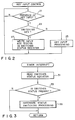
- Fig. 3 is a flowchart showing an operation of the main CPU 17.
- the timer 15 interrupts the main CPU 17.
- the CPU 17 reads, in step 31, the key input status stored in the switched status register 13.
- the CPU 17 determines from the key input status data if a function key indicating a switching of a hardware status is depressed. If the function key indicating the switching of the hardware status is not depressed, the CPU executes a timer interrupt processing operation in step 37.
- the CPU 17 executes a hardware status switching operation in step 35. More specifically, if a function key to switch a CPU clock is depressed, the CPU 17 changes the CPU clock. If a function key indicating a switching among the CRT display, the plasma display, and the liquid crystal display is depressed, the CPU 17 changes the display. If a function key indicating a switching of a display resolution (640 ⁇ 200, 640 ⁇ 350, and 640 ⁇ 480 and the like) of the plasma display is depressed, the CPU 17 changes the display resolution. Furthermore, if a function key indicating a switching between the single font and the double font, the CPU 17 changes the font. Thereafter, the CPU 17 clears the contents of the switched status register 13.
- a key to be detected may be any key other than the function keys.
- any function may be assigned to any key.
Landscapes
- Engineering & Computer Science (AREA)
- Theoretical Computer Science (AREA)
- General Engineering & Computer Science (AREA)
- Physics & Mathematics (AREA)
- General Physics & Mathematics (AREA)
- Software Systems (AREA)
- Human Computer Interaction (AREA)
- Input From Keyboards Or The Like (AREA)
Applications Claiming Priority (2)
| Application Number | Priority Date | Filing Date | Title |
|---|---|---|---|
| JP63074539A JP2597637B2 (ja) | 1988-03-30 | 1988-03-30 | ハードウェア状態切替え制御方式 |
| JP74539/88 | 1988-03-30 |
Publications (2)
| Publication Number | Publication Date |
|---|---|
| EP0335373A2 true EP0335373A2 (fr) | 1989-10-04 |
| EP0335373A3 EP0335373A3 (fr) | 1990-11-28 |
Family
ID=13550180
Family Applications (1)
| Application Number | Title | Priority Date | Filing Date |
|---|---|---|---|
| EP19890105544 Withdrawn EP0335373A3 (fr) | 1988-03-30 | 1989-03-29 | Système d'entrée pour la commande de commutation de l'état d'un matériel |
Country Status (3)
| Country | Link |
|---|---|
| EP (1) | EP0335373A3 (fr) |
| JP (1) | JP2597637B2 (fr) |
| KR (1) | KR920003181B1 (fr) |
Cited By (1)
| Publication number | Priority date | Publication date | Assignee | Title |
|---|---|---|---|---|
| EP0556295A4 (fr) * | 1990-11-09 | 1994-01-12 | Ast Research, Inc. |
Family Cites Families (2)
| Publication number | Priority date | Publication date | Assignee | Title |
|---|---|---|---|---|
| US4684934A (en) * | 1983-02-28 | 1987-08-04 | Data General Corporation | Method and apparatus for storing and retrieving keyboard LED data |
| JPS60225927A (ja) * | 1984-04-25 | 1985-11-11 | Ascii Corp | 複合機能cpuにおけるキ−ボ−ドインタフエ−ス |
-
1988
- 1988-03-30 JP JP63074539A patent/JP2597637B2/ja not_active Expired - Lifetime
-
1989
- 1989-03-29 EP EP19890105544 patent/EP0335373A3/fr not_active Withdrawn
- 1989-03-30 KR KR1019890004162A patent/KR920003181B1/ko not_active Expired
Cited By (1)
| Publication number | Priority date | Publication date | Assignee | Title |
|---|---|---|---|---|
| EP0556295A4 (fr) * | 1990-11-09 | 1994-01-12 | Ast Research, Inc. |
Also Published As
| Publication number | Publication date |
|---|---|
| KR890015126A (ko) | 1989-10-28 |
| JP2597637B2 (ja) | 1997-04-09 |
| JPH01248255A (ja) | 1989-10-03 |
| KR920003181B1 (ko) | 1992-04-23 |
| EP0335373A3 (fr) | 1990-11-28 |
Similar Documents
| Publication | Publication Date | Title |
|---|---|---|
| CA1268556A (fr) | Systeme d'affichage a fenetres pour processus multiples | |
| US4703414A (en) | Programmable controller | |
| JPH0221622B2 (fr) | ||
| US5241646A (en) | Systems for changing hardware parameters using sub-CPU for sensing specialized key inputs and main CPU for changes | |
| US6018336A (en) | Computer system having digitizing tablet | |
| EP0186872B1 (fr) | Protocoles pour terminal | |
| US4841454A (en) | Display controller with a variable scrolling speed, and method for operating same | |
| EP0335373A2 (fr) | Système d'entrée pour la commande de commutation de l'état d'un matériel | |
| JPS62285127A (ja) | マルチウインドウ表示機能を有する表示装置 | |
| JPH09282054A (ja) | 情報処理装置 | |
| JPH0218616A (ja) | コンピュータシステム | |
| JPS6235933A (ja) | カ−ソル移動キ−入力制御方式 | |
| JPS63263515A (ja) | カ−ソル移動キ−制御方式 | |
| KR100205110B1 (ko) | 키보드 제어 시스템 | |
| JPH024004B2 (fr) | ||
| JPS60105034A (ja) | 座標値入力装置 | |
| KR100230240B1 (ko) | 복합 무선호출 장치 및 그 장치의 무선호출 신호처리 방법 | |
| JPH04199213A (ja) | キー入力装置 | |
| JPH06161624A (ja) | 割り込み制御方法 | |
| KR20000015017A (ko) | 키보드에서의 특수기능 구동장치 및 그 구동방법 | |
| JPS63293631A (ja) | 画面分割制御装置 | |
| JPS6235932A (ja) | タイパマチツクキ−ボ−ド入力制御方式 | |
| KR19990084405A (ko) | 다중 사용자 지원 컴퓨터 및 그 방법 | |
| JPH04153739A (ja) | 情報処理装置 | |
| JPH01177628A (ja) | ファンクションキー機能表示方式 |
Legal Events
| Date | Code | Title | Description |
|---|---|---|---|
| PUAI | Public reference made under article 153(3) epc to a published international application that has entered the european phase |
Free format text: ORIGINAL CODE: 0009012 |
|
| 17P | Request for examination filed |
Effective date: 19890426 |
|
| AK | Designated contracting states |
Kind code of ref document: A2 Designated state(s): DE FR GB |
|
| PUAL | Search report despatched |
Free format text: ORIGINAL CODE: 0009013 |
|
| AK | Designated contracting states |
Kind code of ref document: A3 Designated state(s): DE FR GB |
|
| 17Q | First examination report despatched |
Effective date: 19930614 |
|
| STAA | Information on the status of an ep patent application or granted ep patent |
Free format text: STATUS: THE APPLICATION IS DEEMED TO BE WITHDRAWN |
|
| 18D | Application deemed to be withdrawn |
Effective date: 19940419 |