EP0335436A1 - System zum Bewegen einer Schranktür von einer geöffneten in eine geschlossene Position - Google Patents
System zum Bewegen einer Schranktür von einer geöffneten in eine geschlossene Position Download PDFInfo
- Publication number
- EP0335436A1 EP0335436A1 EP89200686A EP89200686A EP0335436A1 EP 0335436 A1 EP0335436 A1 EP 0335436A1 EP 89200686 A EP89200686 A EP 89200686A EP 89200686 A EP89200686 A EP 89200686A EP 0335436 A1 EP0335436 A1 EP 0335436A1
- Authority
- EP
- European Patent Office
- Prior art keywords
- door
- elbow
- extremity
- fixed frame
- shaped horizontal
- Prior art date
- Legal status (The legal status is an assumption and is not a legal conclusion. Google has not performed a legal analysis and makes no representation as to the accuracy of the status listed.)
- Withdrawn
Links
- 238000006073 displacement reaction Methods 0.000 claims abstract description 4
- 210000003414 extremity Anatomy 0.000 claims description 39
- 230000005484 gravity Effects 0.000 claims description 5
- 210000003141 lower extremity Anatomy 0.000 claims description 2
- 210000001364 upper extremity Anatomy 0.000 claims 1
- 238000010276 construction Methods 0.000 description 4
- 210000000056 organ Anatomy 0.000 description 4
- 230000001154 acute effect Effects 0.000 description 1
- 230000000903 blocking effect Effects 0.000 description 1
- 230000003203 everyday effect Effects 0.000 description 1
- 230000007257 malfunction Effects 0.000 description 1
Images




Classifications
-
- E—FIXED CONSTRUCTIONS
- E05—LOCKS; KEYS; WINDOW OR DOOR FITTINGS; SAFES
- E05D—HINGES OR SUSPENSION DEVICES FOR DOORS, WINDOWS OR WINGS
- E05D15/00—Suspension arrangements for wings
- E05D15/28—Suspension arrangements for wings supported on arms movable in horizontal plane
- E05D15/32—Suspension arrangements for wings supported on arms movable in horizontal plane with two pairs of pivoted arms
- E05D15/34—Suspension arrangements for wings supported on arms movable in horizontal plane with two pairs of pivoted arms with wings opening parallel to themselves
-
- E—FIXED CONSTRUCTIONS
- E05—LOCKS; KEYS; WINDOW OR DOOR FITTINGS; SAFES
- E05Y—INDEXING SCHEME ASSOCIATED WITH SUBCLASSES E05D AND E05F, RELATING TO CONSTRUCTION ELEMENTS, ELECTRIC CONTROL, POWER SUPPLY, POWER SIGNAL OR TRANSMISSION, USER INTERFACES, MOUNTING OR COUPLING, DETAILS, ACCESSORIES, AUXILIARY OPERATIONS NOT OTHERWISE PROVIDED FOR, APPLICATION THEREOF
- E05Y2900/00—Application of doors, windows, wings or fittings thereof
- E05Y2900/20—Application of doors, windows, wings or fittings thereof for furniture, e.g. cabinets
Definitions
- the present invention refers to a system for moving the door of a cabinet from an open to a closed position.
- FR-A-2551795 describes a system for moving a door of a cabinet which is essentially constituted by two bracket-shaped horizontal arms in which the two orthogonal branches which form each bracket have the same length and said length is substantially equal to one half of the width of the door to which the two arms are connected. It is evident that for each pair of said arms the cabinet shall have to be constructed exactly since the difference of even one centimetre more or less in the width of the door shall cause serious malfunctions in the door moving system.
- the object of the present invention is the accomplishment of a system which satisfies the above need.
- said cabinet comprising at least one door and one fixed frame constituted by at least one first and one second vertical upright as well as by at least one upper and one lower horizontal shelf, in which said door can be moved in relation to said fixed frame so that the vertical edge of the door next to said first vertical upright when said door is open will then be next to said second vertical upright when said door is closed, said door being moreover connected to said fixed frame by means of two elbow-shaped horizontal arms, each of which is constituted by two branches, by an elbow and by two extremities rotatable round respective pivots, and being the first extremity of one and the other elbow-shaped horizontal arms mounted rotatably on the upper and lower part, respectively, of said fixed frame while the second extremity of one and the other elbow-shaped horizontal arms is mounted rotatably on said door on an upper and a lower point, respectively, arranged on the vertical line which passes through the centre of gravity of said door, characterized in that in each elbow-shaped
- the horizontal arm according to the present invention can move doors having a width which differs by some centimetres from that planned.
- the said first extremity can be fitted in different positions on the fixed frame provided that the distance between the pivot on which rotates said first extremity and the closest point of the door in the closed position is not greater than the length of the first branch of the arm itself.
- the first rotatable extremity of the arms is preferably mounted either on the upper or on the lower extremity, respectively, of the first vertical upright or above said upper or below said lower horizontal shelf, respectively, but very close to said first vertical upright.
- the angle of the elbow is fixed, this is preferably of 90°.
- Said arms can, however, also be made so that the angle of the elbopw is of variable amplitude. This may be obtained, for example, by having a pivot or a bearing between the two branches of the arm.
- This type of construction has the advantage that the branch of the arm between the elbow and the door can be even longer than it can be when angle of the elbow is 90°.
- the angle of the elbow is acute when the door is closed and is 90° when the door is completely open; in this position the further greater length of the second branch of the arm allows for a greater displacement of the door in relation to the second vertical upright so that the entire inner part of the cabinet can be reached even more easily.
- the ratio between the length of the second branch of the horizontal arm and the distance from the pivot of the second rotatable extremity of said horizontal arm to the edge of said door which is next to said second vertical upright in the closed position is equal to or greater than 0.70.
- said ratio has a value between 1 and 1.10, so that the cabinet's access opening is wholly accessible. This result can be attained, in addition to the case with the articulated joint as described above, in several other ways. For example, by having the second branch of the arm between the elbow and the door to telescope along its axis or by moving the centre of gravity of the door towards the second upright.
- both horizontal arms support the weight of the door, so that the weight is uniformly distributed on them.
- the connecting points of the two horizontal arms are arranged on the vertical line which passes through the centre of gravity of said door makes for such balancing of the system which cannot, on the other hand, be obtained in the case of the well-known system constituted by slides and bearings.
- Another feature of the system according to the present invention is that it is almost entirely exempt from failures since its movement is ensured by two pairs of simple pivots.
- a type of guide with a rigid bar suitable for the purpose is described below and is illustrated in the enclosed drawings. Many variations or alternatives may be made to said guide without, however, impairing the required function of permitting the user to open and close the door with one hand only.
- a door 13 equipped with a handle 15 is mounted in a movable way, with respect to said fixed frame, so that the part 14′ of the door 13 which is next to said first vertical upright 11 is subsequently next to said second vertical upright 11′ when the door 13 is closed.
- Fig. 1 also shows part of the rigid bar of the guide 4 whereby the door 13 can be kept in a position that is substantially parallel to the fixed frame during the closing and opening operations.
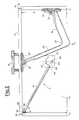
- Fig. 2 shows the position of the elbow-shaped horizontal arm 2, in cross-section, of the guide 4 and of the connecting device 51 and 52, when the door 13 is closed.
- the elbow-shaped horizontal arm 2 according to the present invention is constituted by two branches 24 and 25, by an elbow 23 and by two extremities 21 and 21′, equipped with radial ball bearings, rotatable on their respective pivots 22 and 22′.
- the branch 25 is longer than the branch 24, i.e. their ratio is greater than 1.
- the rotating extremity 21 is, by screws or other suitable fastening means, integral with the vertical upright 11 while the rotatable extremity 21′, is, by screws or other suitable fastening means, integral with the door 13.
- the position and the conformation of the elbow-shaped horizontal arm 2′ under the shelf 12′ has not been illustrated as it is substantially identical with that of arm 2.
- the centre of gravity of the door 13 is on the centre line of the door itself.
- the rotatable extremity 21′ and the corresponding rotatable extremity of the elbow-shaped horizontal arm 2′ are thus mounted on said centre line.
- the distance between the pivot 22, on which the first rotatable extremity 21 rotates, and the elbow 23 is greater than the distance A between said pivot 22 and the closest point of the door 13 in the closed position (Fig. 2), i.e. their ratio is greater than 1.
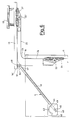
- Said branch 24 will therefore protrude, in the open position (Fig. 6), beyond the fixed frame so that the second branch 25 can line up with the fixed frame. If the door 13 were to be wider than that illustrated, the extremity 21 would be mounted in a position closer to the edge 16 of the upright 11. In which case the distance A would be shorter than that illustrated in Fig.s 2 - 6.
- the ratio between the distance from the elbow 23 to the pivot 22′ of the second extremity of the elbow-shaped horizontal arm (i.e. the length of the second branch 25) and the distance from said pivot 22′ to the vertical edge 14′ of said door which is next to said second upright 11′ in the closed position is about 0.8. This means that about 10% of the cabinet's access opening is still taken up by the door 13 in the open position (Fig. 6).
- Fig.s 2 - 6 also illustrate the structure and the function of the guide 4.
- Said guide is essentially constituted by a housing 42 and by a rigid bar 41 one of whose extremities 47 is connected in a rotatable way to the door 13 while the other extremity 49 is connected to the housing 42 by means of a first pin 44 which is integral with said rigid bar 41 and by means of a second pin 45 which is integral with said housing 42; in addition, said housing 42 has a slit 43 in which said first pin 44 is obliged to move thus determining the displacement of said rigid bar 41 and thus of the door 13, in relation to said second pin 45.
- the upper plate of the housing 42 is connected to another base plate (not illustrated) which, in turn, is fastened to the shelf 12 by screws or other suitable fastening means.
- the two plates are held at a certain distance from one another by suitable means (not illustrated) arranged in any suitable position whatever which does not interfere with the movement of said rigid bar 41.
- the extremity 49 of the rigid bar 41 is equipped with a slot 46 and is mounted in a rotatable and slidable way in relation to the second pin 45 before the upper plate 45 of the housing 42 is made integral with the base plate (not illustrated).
- the rigid bar 41 is also equipped with a pin 44 which, during the assembly operations of the guide 4, is inserted in the slit 43 which defines its path.
- first extremity 47 of the rigid bar 41 is connected in a rotatable way to a pin 50 which is integral with a support 48 fastened to the door by screws or other suitable fastening means and said support 48 is integral with a bracket 51 which, during the closing phase, is superimposed on a small plate 52 fastened to the second vertical upright 11′ of the fixed frame thus causing the connection of said door to said fixed frame (Fig.s 2 and 9).
- the bracket 51 and the small plate 52 have a very important role during the opening phase as well.
- the small plate 52 exerts a certain braking action on the bracket 51 and the vertical edge 14 of the door 13 thus moves away from the vertical upright 11 before the edge 14′ moves away from the vertical upright 11′ (Fig. 3). This allows the door 13 to overlap any adjacent door in a cabinet with more than one door and to superimpose itself on the same.
- Fig. 7, enlarged with respect to Fig.s 2 - 6, illustrates the housing 42 of the guide 4 with the rigid bar 41.
- a spring 40 mounted compressed between the pins 44 and 45. Said spring tends to move the pin 44 away from the pin 45 and this is particularly important in the closed position (Fig.s 2 and 9) because the action of the spring 40 determines the superimposition of the bracket 51 on the small plate 52 and the subsequent blocking of the door 13.
- the pressure exerted on the door 13 by the rigid bar 41 forces the edge 14 to come close to the edge 16 of the upright 11 of the frame so that the cabinet is properly closed.
- Fig. 8 shows a cross-section of the housing 42 and of the terminal part 49 of the rigid bar 41 along the axis B-B′ of Fig. 7 and illustrates its construction details. It can thus be seen that said terminal part 49 is mounted in a rotatable and slidable way, thanks to the slot 46, in relation to the pin 45.
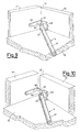
- Fig.s 9 and 10 represent, enlarged and in perspective, the connection device 51 and 52 between the door and the cabinet's fixed frame when the system according to the present invention is in the positions illustrated in Fig.s 2 and 3, respectively.
- the bracket 51 is integral with a support 48 fastened to the door 13 by screws or other suitable fastening means; said support 48 is also equipped with a pin 50 on which the extremity 47 of the rigid bar 41 is mounted in a rotatable way.
- the small plate 52 is the projection of a bracket fastened to the second vertical upright 11′ of the fixed frame by screws or other suitable fastening means.
- the assembly of the branch 25 of the arm 2 on the door may be accomplished, instead of with the rotatable extremity 21′, by equipping the extremity of the arm 25 with a hinge and fastening a suitable device equipped with its female counterpart to the door 13.
Landscapes
- Engineering & Computer Science (AREA)
- Mechanical Engineering (AREA)
- Cabinets, Racks, Or The Like Of Rigid Construction (AREA)
- Hinges (AREA)
Applications Claiming Priority (2)
| Application Number | Priority Date | Filing Date | Title |
|---|---|---|---|
| IT8820012A IT1216642B (it) | 1988-03-29 | 1988-03-29 | Sistema per spostare un'anta di un mobile da una posizione aperta ad una chiusa. |
| IT2001288 | 1988-03-29 |
Publications (1)
| Publication Number | Publication Date |
|---|---|
| EP0335436A1 true EP0335436A1 (de) | 1989-10-04 |
Family
ID=11163109
Family Applications (1)
| Application Number | Title | Priority Date | Filing Date |
|---|---|---|---|
| EP89200686A Withdrawn EP0335436A1 (de) | 1988-03-29 | 1989-03-20 | System zum Bewegen einer Schranktür von einer geöffneten in eine geschlossene Position |
Country Status (4)
| Country | Link |
|---|---|
| US (1) | US4917446A (de) |
| EP (1) | EP0335436A1 (de) |
| JP (1) | JPH02176086A (de) |
| IT (1) | IT1216642B (de) |
Cited By (4)
| Publication number | Priority date | Publication date | Assignee | Title |
|---|---|---|---|---|
| EP0742334A1 (de) * | 1995-05-09 | 1996-11-13 | Modesto Pratolongo | Verbesserte Bewegungsvorrichtung zum Öffnen und Schliessen einer Kleiderschranktür |
| DE202008000760U1 (de) * | 2008-01-18 | 2009-05-28 | Liebherr-Hausgeräte Ochsenhausen GmbH | Kühl- und/oder Gefriergerät |
| WO2009068974A2 (en) | 2007-11-28 | 2009-06-04 | Ezio Terragni | Improved rototranslation mechanism of a shutter of a containment element |
| EP3226723A1 (de) * | 2014-12-03 | 2017-10-11 | Grass GmbH & Co. KG | Vorrichtung zur bewegungskontrolle eines an einem moebelkorpus bewegbar aufgenommenen moebelteils sowie ein moebel mit einer solchen vorrichtung |
Families Citing this family (17)
| Publication number | Priority date | Publication date | Assignee | Title |
|---|---|---|---|---|
| IT1228769B (it) * | 1989-03-29 | 1991-07-03 | Mariani Enrico | Dispositivo per la connessione girevole e regolabile di un braccio ad una piatra di fissaggio. |
| US6282847B1 (en) * | 1999-05-27 | 2001-09-04 | Genesis Systems Group, Ltd. | Workcell door and wall assembly |
| US7988398B2 (en) | 2002-07-22 | 2011-08-02 | Brooks Automation, Inc. | Linear substrate transport apparatus |
| US7959395B2 (en) | 2002-07-22 | 2011-06-14 | Brooks Automation, Inc. | Substrate processing apparatus |
| US6922874B2 (en) * | 2003-03-31 | 2005-08-02 | Phonak Ag | Housing cover for electronic microdevices |
| US7735261B2 (en) * | 2007-09-27 | 2010-06-15 | Strike Industries, Inc. | Self-locking door assembly |
| GB2472243A (en) * | 2009-07-30 | 2011-02-02 | Usystems Limied | A cabinet door which slides outwardly in a horizontal plane |
| US8602706B2 (en) * | 2009-08-17 | 2013-12-10 | Brooks Automation, Inc. | Substrate processing apparatus |
| DE102010007129A1 (de) * | 2010-02-05 | 2011-08-11 | Heinrich J. Kesseböhmer KG, 49152 | Beschlag für Eckschränke |
| EP2353436B1 (de) * | 2010-02-05 | 2012-11-14 | Hetal-Werke Franz Hettich GmbH & Co. | Beschlag für einen Eckschrank und Eckschrank |
| US20120037051A1 (en) * | 2010-08-16 | 2012-02-16 | Pi-Liang Wang | Computer Table That Is Folded and Expanded Easily And Quickly |
| KR101704817B1 (ko) * | 2010-08-20 | 2017-02-08 | 엘지전자 주식회사 | 냉장고 |
| EP2713816B1 (de) * | 2011-05-23 | 2016-01-27 | Kesseböhmer Holding e.K. | Beschlag für eckschränke |
| ITTV20110070A1 (it) * | 2011-05-23 | 2012-11-24 | Bortoluzzi Lab S R L | Dispositivo per ante scorrevoli a chiusura complanare, particolarmente per mobili e simili |
| US8794722B2 (en) * | 2013-01-08 | 2014-08-05 | General Electric Company | Drawer assembly for an appliance |
| US10876341B2 (en) * | 2018-07-24 | 2020-12-29 | Brose Fahrzeugteile Gmbh & Co. Kommanditgesellschaft, Bamberg | Door drive system |
| US20220389743A1 (en) * | 2021-06-02 | 2022-12-08 | Magna BOCO GmbH | Power door linkage system for b-pillarless door system for motor vehicles |
Citations (4)
| Publication number | Priority date | Publication date | Assignee | Title |
|---|---|---|---|---|
| CH318747A (de) * | 1956-03-29 | 1957-01-31 | Kaessbohrer Fahrzeug Karl | Schwingtüre, insbesondere für Fahrzeuge |
| FR2219686A5 (de) * | 1973-02-24 | 1974-09-20 | Kloeckner Humboldt Deutz Ag | |
| DE2722251A1 (de) * | 1977-05-17 | 1978-11-23 | Interluebke Kg | Beschlag fuer tueren o.dgl. |
| FR2551795A1 (fr) * | 1983-09-09 | 1985-03-15 | Lespingal Jean Pierre | Charniere pour porte et porte equipee de cette charniere |
Family Cites Families (5)
| Publication number | Priority date | Publication date | Assignee | Title |
|---|---|---|---|---|
| US2161323A (en) * | 1938-08-15 | 1939-06-06 | Om Edwards Co Inc | Latch mechanism for desk tops |
| US2919966A (en) * | 1957-04-01 | 1960-01-05 | Acme Appliance Mfg Company | Retractable shelf |
| US3175761A (en) * | 1964-03-16 | 1965-03-30 | R F D Archie L Moore | Door balancer construction |
| CH442077A (de) * | 1964-03-20 | 1967-08-15 | Bofors Ab | Vorrichtung zum Befestigen eines Deckels an einer Wand, insbesondere eines Deckels einer Einsteigöffnung einer fahrbaren Kanone oder dergleichen |
| DE2950857C2 (de) * | 1979-12-18 | 1985-02-14 | Team Form Ag, Hinwil | Türbeschlag zur Parallelführung einer Tür |
-
1988
- 1988-03-29 IT IT8820012A patent/IT1216642B/it active
-
1989
- 1989-03-20 EP EP89200686A patent/EP0335436A1/de not_active Withdrawn
- 1989-03-27 US US07/329,164 patent/US4917446A/en not_active Expired - Fee Related
- 1989-03-29 JP JP1075240A patent/JPH02176086A/ja active Pending
Patent Citations (4)
| Publication number | Priority date | Publication date | Assignee | Title |
|---|---|---|---|---|
| CH318747A (de) * | 1956-03-29 | 1957-01-31 | Kaessbohrer Fahrzeug Karl | Schwingtüre, insbesondere für Fahrzeuge |
| FR2219686A5 (de) * | 1973-02-24 | 1974-09-20 | Kloeckner Humboldt Deutz Ag | |
| DE2722251A1 (de) * | 1977-05-17 | 1978-11-23 | Interluebke Kg | Beschlag fuer tueren o.dgl. |
| FR2551795A1 (fr) * | 1983-09-09 | 1985-03-15 | Lespingal Jean Pierre | Charniere pour porte et porte equipee de cette charniere |
Cited By (5)
| Publication number | Priority date | Publication date | Assignee | Title |
|---|---|---|---|---|
| EP0742334A1 (de) * | 1995-05-09 | 1996-11-13 | Modesto Pratolongo | Verbesserte Bewegungsvorrichtung zum Öffnen und Schliessen einer Kleiderschranktür |
| WO2009068974A2 (en) | 2007-11-28 | 2009-06-04 | Ezio Terragni | Improved rototranslation mechanism of a shutter of a containment element |
| WO2009068974A3 (en) * | 2007-11-28 | 2009-09-03 | Ezio Terragni | Improved rototranslation mechanism of a shutter of a containment element |
| DE202008000760U1 (de) * | 2008-01-18 | 2009-05-28 | Liebherr-Hausgeräte Ochsenhausen GmbH | Kühl- und/oder Gefriergerät |
| EP3226723A1 (de) * | 2014-12-03 | 2017-10-11 | Grass GmbH & Co. KG | Vorrichtung zur bewegungskontrolle eines an einem moebelkorpus bewegbar aufgenommenen moebelteils sowie ein moebel mit einer solchen vorrichtung |
Also Published As
| Publication number | Publication date |
|---|---|
| JPH02176086A (ja) | 1990-07-09 |
| IT1216642B (it) | 1990-03-08 |
| IT8820012A0 (it) | 1988-03-29 |
| US4917446A (en) | 1990-04-17 |
Similar Documents
| Publication | Publication Date | Title |
|---|---|---|
| US4917446A (en) | System for moving the door of a cabinet from an open to a closed position | |
| US4644690A (en) | Sliding door structure | |
| US3912350A (en) | Anti-tip mechanism for appliance | |
| US10488882B2 (en) | Electronic device hinge assembly | |
| EP1327841B1 (de) | Kühlschrank mit zweiachsigem Türscharnier | |
| US6318824B1 (en) | Hinged tracking system | |
| US6336246B1 (en) | Door mounting mechanism and assembly for door opening-closing with movements at right angles | |
| US10092094B2 (en) | Fitting for a corner cupboard and corner cupboard with fitting | |
| US4236272A (en) | Hinge comprising a compression spring, which is adapted to balance the weight of a hinged leaf | |
| JPS61130584A (ja) | 回転ドアの自動閉扉および開扉保持装置 | |
| US4132034A (en) | Refrigerator door with double acting hinge | |
| JP3408819B2 (ja) | 配電箱のための作業プレート | |
| US11441346B2 (en) | Hinged door leaves for wardrobes, walk-in closets and pieces of furniture in general, provided with magnetic damping and return devices | |
| US10526827B2 (en) | Hinge for furniture leaves that open downwardly | |
| US5493759A (en) | Articulated furniture hinge having a pivotally adjustable hinge arm producing lateral or vertical member translation | |
| US6007171A (en) | Cabinet with over-the-top door | |
| US5368377A (en) | Flip-top computer workstation | |
| KR102586942B1 (ko) | 가구 도어의 움직임을 위한 기구 | |
| US6094866A (en) | System for opening and closing doors in furniture, rooms and the like | |
| US5231711A (en) | Apparatus for opening and closing folding bed | |
| US1700201A (en) | Sectional roll-top desk | |
| US4139116A (en) | Cabinet with two or more drawers | |
| EP4350112A1 (de) | Vorrichtung zum öffnen und schliessen von falttüren eines möbelschranks und mit falttüren versehener möbelschrank | |
| US4382644A (en) | Bearing device for sliding panels, particularly for a piece of furniture | |
| US4108512A (en) | Cabinet mounting unit for free arm sewing machine |
Legal Events
| Date | Code | Title | Description |
|---|---|---|---|
| PUAI | Public reference made under article 153(3) epc to a published international application that has entered the european phase |
Free format text: ORIGINAL CODE: 0009012 |
|
| AK | Designated contracting states |
Kind code of ref document: A1 Designated state(s): AT BE CH DE ES FR GB GR IT LI LU NL SE |
|
| 17P | Request for examination filed |
Effective date: 19900207 |
|
| 17Q | First examination report despatched |
Effective date: 19920320 |
|
| STAA | Information on the status of an ep patent application or granted ep patent |
Free format text: STATUS: THE APPLICATION IS DEEMED TO BE WITHDRAWN |
|
| 18D | Application deemed to be withdrawn |
Effective date: 19920731 |