EP0335531B1 - Couplage de fibres optiques - Google Patents
Couplage de fibres optiques Download PDFInfo
- Publication number
- EP0335531B1 EP0335531B1 EP89302594A EP89302594A EP0335531B1 EP 0335531 B1 EP0335531 B1 EP 0335531B1 EP 89302594 A EP89302594 A EP 89302594A EP 89302594 A EP89302594 A EP 89302594A EP 0335531 B1 EP0335531 B1 EP 0335531B1
- Authority
- EP
- European Patent Office
- Prior art keywords
- coupling
- plug
- panel
- housing
- end portion
- Prior art date
- Legal status (The legal status is an assumption and is not a legal conclusion. Google has not performed a legal analysis and makes no representation as to the accuracy of the status listed.)
- Expired - Lifetime
Links
Images



Classifications
-
- G—PHYSICS
- G02—OPTICS
- G02B—OPTICAL ELEMENTS, SYSTEMS OR APPARATUS
- G02B6/00—Light guides; Structural details of arrangements comprising light guides and other optical elements, e.g. couplings
- G02B6/24—Coupling light guides
- G02B6/36—Mechanical coupling means
- G02B6/38—Mechanical coupling means having fibre to fibre mating means
- G02B6/3807—Dismountable connectors, i.e. comprising plugs
- G02B6/3873—Connectors using guide surfaces for aligning ferrule ends, e.g. tubes, sleeves, V-grooves, rods, pins, balls
- G02B6/3874—Connectors using guide surfaces for aligning ferrule ends, e.g. tubes, sleeves, V-grooves, rods, pins, balls using tubes, sleeves to align ferrules
-
- G—PHYSICS
- G02—OPTICS
- G02B—OPTICAL ELEMENTS, SYSTEMS OR APPARATUS
- G02B6/00—Light guides; Structural details of arrangements comprising light guides and other optical elements, e.g. couplings
- G02B6/24—Coupling light guides
- G02B6/36—Mechanical coupling means
- G02B6/38—Mechanical coupling means having fibre to fibre mating means
- G02B6/3807—Dismountable connectors, i.e. comprising plugs
- G02B6/381—Dismountable connectors, i.e. comprising plugs of the ferrule type, e.g. fibre ends embedded in ferrules, connecting a pair of fibres
- G02B6/3826—Dismountable connectors, i.e. comprising plugs of the ferrule type, e.g. fibre ends embedded in ferrules, connecting a pair of fibres characterised by form or shape
- G02B6/3831—Dismountable connectors, i.e. comprising plugs of the ferrule type, e.g. fibre ends embedded in ferrules, connecting a pair of fibres characterised by form or shape comprising a keying element on the plug or adapter, e.g. to forbid wrong connection
-
- G—PHYSICS
- G02—OPTICS
- G02B—OPTICAL ELEMENTS, SYSTEMS OR APPARATUS
- G02B6/00—Light guides; Structural details of arrangements comprising light guides and other optical elements, e.g. couplings
- G02B6/24—Coupling light guides
- G02B6/36—Mechanical coupling means
- G02B6/38—Mechanical coupling means having fibre to fibre mating means
- G02B6/3807—Dismountable connectors, i.e. comprising plugs
- G02B6/3833—Details of mounting fibres in ferrules; Assembly methods; Manufacture
- G02B6/3851—Ferrules having keying or coding means
-
- G—PHYSICS
- G02—OPTICS
- G02B—OPTICAL ELEMENTS, SYSTEMS OR APPARATUS
- G02B6/00—Light guides; Structural details of arrangements comprising light guides and other optical elements, e.g. couplings
- G02B6/24—Coupling light guides
- G02B6/36—Mechanical coupling means
- G02B6/38—Mechanical coupling means having fibre to fibre mating means
- G02B6/3807—Dismountable connectors, i.e. comprising plugs
- G02B6/389—Dismountable connectors, i.e. comprising plugs characterised by the method of fastening connecting plugs and sockets, e.g. screw- or nut-lock, snap-in, bayonet type
- G02B6/3891—Bayonet type
-
- G—PHYSICS
- G02—OPTICS
- G02B—OPTICAL ELEMENTS, SYSTEMS OR APPARATUS
- G02B6/00—Light guides; Structural details of arrangements comprising light guides and other optical elements, e.g. couplings
- G02B6/24—Coupling light guides
- G02B6/36—Mechanical coupling means
- G02B6/38—Mechanical coupling means having fibre to fibre mating means
- G02B6/3807—Dismountable connectors, i.e. comprising plugs
- G02B6/3897—Connectors fixed to housings, casing, frames or circuit boards
Definitions
- This invention relates to an optical fiber coupling.
- a local area network system or loop distribution plant is effective to connect each telephone customer to a central office through a transmission medium.
- the transmission medium commonly is a twisted pair of insulated copper conductors which, for most of its length, is disposed in a multipair cable.
- W086/00423 discloses a coupling as defined in the preamble of claim 1.
- DE-A-27 41 585 discloses a coupling to be mounted in a housing.
- the coupling serves to provide termination for an optical fiber, and comprises first and second end portions.
- optical fiber interface electronic devices which are required for an optical fiber loop are not yet generally available.
- loop architecture and media also should be available so that devices can be connected immediately into the loop. Accordingly, it becomes important to provide a system which will provide service from those optical devices now in development to customer premises.
- each remote terminal is designated to provide service to a plurality of distribution points.
- Optical fiber is to be extended from optical units of the remote terminal to an interconnection portion whereat it is connected to runs which extend to branch-outs.
- an incoming optical fiber is connected, for example, by a prealigned rotary splice shown in U.S. Patent 4,691,986 which issued on September 9,1987 in the names of J.A. Aberson, et al. to a distribution drop. From a distribution drop, service is provided by a drop cable to each of a plurality of homes in a subdivision, for example.
- each frame adapted to receive a plurality of cards.
- Each card which includes a laser, a splitter and a detector, for example, is adapted to be connected through a coupling which is mounted in a panel to a jumper cable which extends to the interconnection portion of the remote terminal.
- a panel is referred to commonly as a backplane.
- the card may be provided with a modified ST® connector, for example.
- ST® connector for example.
- the optical connection portion allows interconnections and/or cross connections of a connector end of each jumper cable to an optical fiber of a cable which extends outwardly to the branch-outs of the loop plant.
- the outgoing cable from the interconnection portion of the remote terminal extends to a primary closure. From the primary closure, smaller cables extend to intermediate closures and thence to drop closures. Each of the drop closures is adapted to provide service to a plurality of customer premises.
- each home will be provided with a service unit mounted on the exterior of the home.
- Each of these units will include a panel-mounted backplane coupling adapted to receive an ST® connector, for example, at one end thereof.
- An opposite end of the backplane coupling which may be the same as that coupling which is mounted in the remote terminal, is adapted to receive a modified ST® connector which terminates a lead from a card-mounted splitter.
- the center-to-center spacing may be as low as 1.12 cm.
- Each card must be capable of being inserted repeatedly to provide a low-loss, low reflection optical connection, and yet there is very little room in which a craftsman can make a connection.
- the sought-after coupling also must be rugged and must insure that alignment of the ST® connectors occurs albeit accomplished in the confines of a congested backplane.
- each card is connected to the backplane coupling by a craftsman who causes the card to be moved into a slotted opening in a frame.
- the card is caused to be moved toward the coupling until the modified ST® connector at it leading end is inserted into one end of its associated coupling and then into one end of an alignment sleeve which is disposed within the coupling.
- the connector insertion is a blind one, that is the craftsman cannot view directly the coupling as the card connector is moved toward it.
- Blind insertion raises two problems. First, a physical insertion must take place, otherwise the end face of the connector could be damaged, and/or no optical connection will take place. Also, a frequent happening is an excessively angled insertion of the connector plug into the coupling which may cause the sleeve to break. Further, the canting of the connector with respect to the sleeve results in misalignment with the connector plug at an opposite end of the coupling as well as excessive reflection.
- the coupling includes a housing comprising a first end portion and a second end portion with a flange being disposed between the first and second end portions.
- the first end portion is adapted to receive a plug which terminates an optical fiber.
- a sleeve is disposed in the housing and is recessed therewithin. The sleeve is adapted to receive in each of its ends a plug which terminates an optical fiber.
- the coupling has an entrance to the second end portion thereof which is tapered from a large diameter portion at the entrance to a small diameter adjacent to the sleeve.
- the housing is mounted in a support panel in a manner which permits movement of the housing.
- Mounting facilities are provided for supporting the housing in the panel in such a manner as to permit movement in any one or more of three dimensions as a plug is inserted into the second end portion of the housing. Also, the mounting facilities cause the housing to be biased toward its second end portion and the flange to become seated in engagement with the panel. The mounting facilities are effective to cause insertion of the plug into the second end portion of the housing to be accomplished in a manner so that the plug at worst engages the tapered entrance thereby avoiding damage to the end face of the plug: particularly to the optical fiber terminated therein.
- the mounting facilities are effective to minimize any turning movement of the coupling about an axis transverse to its longitudinal axis and to cause any movement of the coupling during insertion of a plug into the second end portion to be substantially translatory with respect to its longitudinal axis.
- the just-described arrangement is advantageous in that as a plug end of a card, for example, is inserted into the housing, the plug is cammed by the tapered wall into the sleeve. Also, the mounting of the housing allows the housing to be moved by the plug to accommodate the insertion. Advantageously, substantially all the movement of the coupling is translatory with respect to the longitudinal axis.
- FIG. 1 there is shown a schematic view of a distribution and service cable system which includes an optical fiber coupling 20 of this invention.
- This system which is designated generally the numeral 22, is adapted to provide optical fiber cable service to customers' premises. It is intended to be used instead of or to replace prior art metallic conductor communications distribution systems.
- an area has been subdivided into a plurality of lots or customer using units 21-21 with a plurality of lots comprising a unit 23.
- Front lot lines of opposing lots are spaced apart by a roadway 24.
- a plurality of units 23-23 are separated from another plurality by a right-of-way designated with a numeral 25.
- the distribution system includes a remote terminal and/or serving area interface 26. From the remote terminal 26 along a right-of-way to a branch-out 27 extends a cable 28 adapted to provide communications service for a plurality of the units 23-23. In order to accomplish this, a plurality of distribution cable segments 29-29 extend from each branch-out to a plurality of secondary closures 30-30.
- Each of the remote terminals 26-26 includes a connecting panel 32 and an interconnection portion 34.
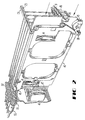
- a frame 36 (see FIG. 2) to one side of the connecting panel or backplane 32 is provided with a plurality of slots 38-38, each adapted to receive a card 40.
- Each card 40 is provided with a laser 41, detector 44 and splitter (not shown) with the splitter connected to a plug or ferrule, as it is often called, of a connector 48 such as a modified ST® connector.
- An ST® connector is disclosed in U.S. patent 4,634,214.
- Each card 40 includes a plurality of electrical contacts 42-42 which are adapted to be received in a connector 46 which is connected through other equipment (not shown) to a central office.
- FIG. 2 Facilities are provided for securing each card 40 in the frame 36.
- an installer moves a pivotally mounted member 45 in a counterclockwise direction as viewed in FIG. 2 to cause a portion 43 to engage a portion 47 of the frame 36. Also, this causes a latch portion (not shown) to latch to a keeper 49 of the card.
- the installer compresses furcations of a bifurcated portion 51 to release the latch portion and moves pivotally the portion 43 from locking engagement with the portion 47 of the frame.
- each card 40 is adapted to be inserted into one end 49 of the coupling 20 (see FIGS. 3 and 4) of this invention which also is referred to herein as the backplane coupling and which is mounted on the panel 32.
- An opposite end 52 of the backplane coupling 20 is adapted to receive a plug 54 of an ST® connector 55, for example, which terminates one end of a jumper 56 (see FIG. 1).
- the other end of the jumper 56 also may be terminated with an ST® connector which is received on one portion of the interconnection portion 34 of the remote terminal 26.
- Optical fibers of the cable 28 are terminated in another portion of the interconnection portion 34 of the remote terminal 26 and then connected to selected ones of the terminated jumper ends.
- the cable 28 is routed to the primary closure or branch-out 27 from which the smaller cables 29-29 extend to the closures 30-30.
- Each closure 30 is adapted to be connected to a drop closure 58 which provides service to two customer units 21-21 which may be homes, for example.
- an enclosure attached to the outside wall houses another card 40 which mounts to another backplane coupling 20.
- Another end of the coupling receives a connector which terminates an end of a service cable which extends from the drop closure 58 to the customer unit.
- the coupling 20 is adapted to couple together two cylindrical plug type connectors such as, for example, the well known ST® connector. It should be understood that the coupling 20 could be used to couple together other cylindrical plug connectors as well.
- the coupling 20 includes a housing 70 which includes the card end 49 and the jumper end 52.
- the housing 70 includes a flared opening 76 which communicates with a cylindrical bore 78.
- the cylindrical bore 78 has a diameter which is slightly greater than that of a plug 80 of the connector 48 to be received therein.
- the cylindrical bore 78 opens to an enlarged passageway 82 of the housing in which is received a cylindrical alignment sleeve 84.
- the alignment sleeve 84 is adapted to receive a connector plug in each end and to cause the end portions thereof to be aligned. Accordingly, the transverse cross section of the sleeve as defined by its inner diameter is such as to provide an interference fit with the plugs to be received therein.
- a split retaining ring 86 having diametrically opposed ears 88-88 (see FIG. 4) is seated in engagement with an annular shoulder 89 formed between the passageway 82 and a cavity 91. As the split retaining ring is moved along the cavity 91 and into engagement with the shoulder 89, the ears 88-88 of the ring, which had been compressed, spring outwardly into openings 93-93 in the housing to lock the sleeve within the housing.
- the ring 86 is sized so that it projects inwardly beyond a surface 95 which defines the passageway 82 and hence prevents the sleeve from being moved inadvertently out of the housing.
- the opening in the ring is equal substantially to that of the sleeve to permit a plug of another connector, which in the preferred embodiment is connected to a jumper cable 56, to be moved into the sleeve to abut the leading end of the plug 80 of the card 40.
- the coupling 20 is mounted in the opening 99 of the backplane panel 32.
- a compression spring 102 which is held thereon by a retaining ring 104 seated in a groove 105 of the housing.
- the spring 102 causes a flange 107 of the coupling to be held in engagement in the panel 32.
- each end of the spring 102 engages a washer 103 which is made of a material which has a relatively low coefficient of friction with respect to the material of the spring 102.
- the washers 103-103 preferably are made of an acetal material such as, for example, DELRIN® resin which has a relatively low coefficient of friction relative to that of stainless steel.
- DELRIN is a registered trademark of the E.I. DuPont de Nemours Company.
- One of the washers 103-103 is disposed between the spring 102 and the panel 32 and one between the spring and the retaining ring 104.
- the washers 103-103 are advantageous in causing the connection through the coupling to be one which is relatively low loss, low reflection. Without the washers 103-103 or with washers having a high coefficient of friction, insertion of the plug 80 could result in an undue amount of turning of the coupling 20 about an axis transverse to a longitudinal axis 106 of the coupling.
- the washers 103-103 are able readily to slide with respect to the spring 102 and thereby help to cause any movement of the coupling to be substantially translatory.
- the opening 99 through the backplane panel 32 is sized to be about 0.15 cm larger than the housing (see FIG. 5) thereby permitting movement of the housing of 0.15 cm, for example, in each of two directions.
- the disposition of the spring 102 about the housing 70 allows a third dimensional movement of the housing in a direction axially of the longitudinal axis of the housing.
- the spring is such as to allow an axial movement of about 0.15 cm.
- the housing is provided with a longitudinally extending key 108 (see FIG. 5) that is received in a slot 109 extending radially from the oversize opening 99 in the panel.
- the insertion of the card plug into the backplane coupling is a blind one. With so many cards to be mounted on the couplings 20-20 in the panel 32 and with the center-to-center spacing therebetween being only about 1.12 cm, provisions must be made to facilitate such insertions and to prevent damage to the coupling sleeve.
- Provisions of the backplane coupling 20 of this invention facilitate card plug insertion and prevent damage during each insertion.
- the entrance to the card end 49 of the coupling housing 70 is flared.
- the tolerances of the card and of the coupling and its mounting are such that, at worst, the plug 80 if not aligned with the sleeve opening upon insertion of the card engages the flared portion 76 of the coupling entrance (see FIG. 3).
- the plug 80 cams against the flared wall eliminating the possibility of damage to the optical fiber which terminates in an end face of the plug.
- the camming of the card plug against this flared wall applies forces to the coupling. Because of the oversize opening 99 in the panel 32 in which the housing 70 is received, the housing is able to be moved by the card 40 to accommodate the plug 80 of the card. Further, the spring mounting of the housing 70 allows longitudinal movement of the housing as the plug 80 is being inserted.
- the coupling 20 is configured to minimize canting of the plug 80 as the plug is inserted therewithin (see FIGS. 6 and 7).
- the length of the cylindrical bore 78 longitudinally of the housing 70 is designated L and the diameter of the bore is designated D. It has been found that by controlling the ratio of D/L, the degree of canting of the plug 80 of the card 40 that is inserted into the housing 70 is controlled. Preferably, the ratio D/L is about 2.5.
- any turning of the coupling 20 as the card plug is inserted is about 1 ° or less.
- reflection and insertion loss are minimized.
- the probability of sleeve damage during insertion of the plug becomes substantially zero.
- the card plug 80 may be inserted into the sleeve 84 either before or after a plug which terminates a jumper 56, for example, is inserted into the opposite end 52 of the housing. After both plugs have been inserted into the sleeve 84, the end faces of the plugs engage each other (see FIGS. 4 and 8).
Landscapes
- Physics & Mathematics (AREA)
- General Physics & Mathematics (AREA)
- Optics & Photonics (AREA)
- Mechanical Coupling Of Light Guides (AREA)
- Optical Couplings Of Light Guides (AREA)
Claims (10)
- Couplage (20) gui est adapté pour être monté dans un panneau, ledit couplage comprenant un logement (70) comprenant des première et seconde parties d'extrémité (49), chaque dite partie d'extrémité étant adaptée pour recevoir une fiche gui termine une fibre optique ledit logement comprenant en outre un manchon (84) qui est disposé dans ledit logement, en retrait par rapport au moins à la seconde partie d'extrémité de celui-ci et adapté pour recevoir dans chaque partie d'extrémité de celui-ci une fiche gui termine une fibre optique, caractérisé en ce qu'au niveau de ladite seconde partie d'extrémité ledit logement a une ouverture (76) qui est conique depuis une partie de grand diamètre à l'entrée jusqu'à une partie de petit diamètre contiguë audit manchon (84), ladite partie de petit diamètre ayant une section transversale qui est égale ou supérieure à la section transversale définie par un diamètre interne dudit manchon et dans lequel ladite partie de petit diamètre de ladite ouverture comporte un alésage cylindrique (78) s'étendant entre ladite partie conique et ledit manchon, la section transversale dudit alésage cylindrique étant égale ou supérieure à la section transversale définie par le diamètre interne dudit manchon; et
des moyens de montage (102,103) sont fournis pour soutenir ledit logement (70) dans une ouverture d'un panneau de façon à permettre le déplacement dans l'une quelconque ou plusieurs de trois directions orthogonales quand une fiche est insérée dans ladite seconde partie d'extrémité dudit logement, le rapport diamètre/longueur de l'alésage cylindrique étant tel que l'alésage cylindrique et le moyen de montage coopèrent de façon à minimiser tout déplacement tournant dudit couplage autour d'un axe transversal à son axe longitudinal et à faire en sorte que tout déplacement dudit couplage durant l'insertion d'une fiche dans ladite seconde partie d'extrémité soit substantiellement un déplacement de translation dans la direction de l'axe longitudinal. - Couplage selon la revendication 1, dans lequel ledit manchon (84) est maintenu au sein dudit logement par un anneau de retenue (86-89) qui est disposé contigu à ladite première partie d'extrémité dudit logement.
- Couplage selon la revendication 1, dans lequel ledit moyen de montage comporte une bride (107) entourant ledit logement entre lesdites première et seconde parties d'extrémité de celui-ci, ladite bride étant adaptée pour engager un panneau ayant une ouverture dans laquelle ledit couplage est inséré.
- Couplage selon la revendication 3, dans lequel ledit couplage est adapté pour être monté dans un panneau, ledit couplage s'étendant à travers une ouverture dans le panneau, ledit couplage comportant en outre un moyen d'accumulation d'énergie (102) qui est disposé autour d'une partie dudit couplage entre le panneau et ladite seconde partie d'extrémité dudit couplage et un moyen de retenue (104) fixé audit couplage contigu à ladite seconde partie d'extrémité de celui-ci, ledit moyen d'accumulation d'énergie étant efficace pour charger préliminairement ladite bride (107) dudit couplage en engagement avec ledit panneau et permettre un déplacement prédéterminé dudit couplage dans une direction le long de l'axe longitudinal dudit couplage quand une fiche qui termine une fibre optique est insérée dans ladite seconde partie d'extrémité dudit logement.
- Couplage selon la revendication 4, dans lequel ledit moyen d'accumulation d'énergie comprend un ressort qui est disposé concentriquement autour dudit logement et ledit moyen de montage comporte deux organes annulaires (103), dont l'un est disposé entre ledit ressort et le panneau et l'autre entre ledit ressort et ledit moyen de retenue, lesdits organes annulaires étant d'un matériau qui a un coefficient de friction relativement faible par rapport à celui dudit ressort.
- Arrangement de couplage adapté pour recevoir dans une première partie d'extrémité de celui-ci une fiche qui termine une fibre optique et dans l'autre partie d'extrémité de celui-ci une fiche qui termine une carte à laquelle doit être connectée ladite fibre, ledit arrangement comportant un panneau (32) ayant une ouverture à travers, et un couplage tel que présenté à la revendication 1 s'étendant à travers ladite ouverture (99) dans ledit panneau, ladite ouverture dans ledit panneau étant plus grande qu'une section transversale dudit couplage de telle sorte que lorsqu'une fiche de carte est insérée dans ladite seconde partie d'extrémité dudit couplage, la fiche de carte si elle n'est pas alignée avec ledit manchon butera contre une paroi qui définit ladite extrémité conique de ladite seconde partie d'extrémité dudit logement et forcera le repositionnement dudit couplage au sein de ladite ouverture dans ledit panneau pour que ledit manchon soit aligné avec la fiche de carte.
- Arrangement de couplage selon la revendication 6, dans lequel ledit moyen de montage comporte un ressort qui est disposé autour d'une partie dudit logement entre le panneau et un organe de retenue contigu à ladite seconde partie d'extrémité dudit logement, ledit couplage comportant deux organes annulaires dont chacun engage une extrémité dudit ressort et qui ont un coefficient de friction relativement faible par rapport au matériau dudit ressort, l'application de forces audit couplage forçant la compression dudit ressort et le déplacement longitudinal dudit couplage au sein de ladite ouverture dans ledit panneau, dans lequel ledit panneau comporte une fente qui s'ouvre à ladite ouverture est [sic] ledit panneau, et ledit couplage comportant une clavette s'étendant longitudinalement qui est adaptée pour être reçue dans ladite fente quand ledit couplage est monté dans ladite ouverture pour empêcher la rotation accidentelle dudit couplage dans ladite ouverture et dans lequel le rapport du diamètre dudit alésage cylindrique sur la longueur de l'alésage étant [sic] contrôlé pour coopérer avec les organes annulaires qui sont faits en un matériau ayant un coefficient de friction qui est relativement faible par rapport à celui du ressort pour limiter tout coincement de la fiche de carte si la fiche de carte n'était pas alignée avec le manchon quand la fiche de carte est insérée dans la seconde partie d'extrémité du logement.
- Arrangement pour fournir des signaux entre un bureau central et un point d'interconnexion dans un réseau local, ledit arrangement comprenant:
une pluralité de cartes (40) ayant chacune au moins un composant optique monté dessus et ayant une fiche s'étendant depuis une extrémité de celle-ci, ladite fiche terminant une fibre optique qui s'étend depuis un composant sur ladite carte;
une pluralité de glissières (38) chacune étant adaptée pour recevoir une carte;
un panneau (32) ayant une pluralité d'ouvertures à l'intérieur, chacune desdites ouvertures étant alignée avec l'une desdites glissières pour l'une desdites cartes;
une pluralité de couplages (20) tels que présentés à la revendication 1, dont chacun est monté dans l'une associée desdites ouvertures dans ledit panneau et destiné à être associé à l'une desdites cartes;
chaque dite ouverture dans ledit panneau étant plus grande qu'une section transversale dudit couplage disposé à l'intérieur de telle sorte que ledit couplage peut être repositionné dans ladite ouverture associée;
l'arrangement étant tel que lorsqu'une carte est déplacée le long de l'une des glissières la fiche de la carte étant placée dans ledit couplage, ladite fiche engagera au moins l'entrée conique de l'ouverture du logement dans lequel elle doit être insérée; et
une pluralité de câbles de raccordement, adaptés chacun pour être connectés à l'une desdites cartes, chacun desdits câbles de raccordement étant terminé par une fiche qui est reçue dans une première partie d'extrémité de l'un desdits couplages. - Arrangement selon la revendication 8, dans lequel la fiche de carte (48) si elle n'est pas alignée avec ledit manchon butera contre une paroi qui définit l'entrée conique de ladite seconde partie d'extrémité et forcera le repositionnement dudit couplage au sein de ladite ouverture dans ledit panneau pour que ledit manchon soit aligné avec la fiche de carte.
- Arrangement selon la revendication 8, dans lequel ledit moyen de montage comporte un ressort qui est disposé concentriquement autour dudit logement entre le panneau et un anneau de retenue contigu à ladite seconde partie d'extrémité dudit logement et comporte en outre deux rondelles, dont l'une est disposée entre ledit ressort et le panneau et l'autre entre ledit ressort et ledit anneau de retenue, lesdites rondelles étant en un matériau qui a un coefficient de friction relativement faible par rapport à celui dudit ressort, et dans lequel ladite partie de petit diamètre du logement comporte un alésage cylindrique disposé entre ladite entrée conique et ledit manchon, la section transversale dudit alésage cylindrique étant au moins égale à celle définie par le diamètre interne dudit manchon, et le rapport du diamètre de l'alésage sur la longueur dudit alésage cylindrique étant contrôlé pour coopérer avec les rondelles qui sont faites en un matériau au coefficient de friction relativement faible pour limiter tout coincement de la fiche de carte si la fiche de carte n'était pas alignée avec le manchon quand la fiche de carte est insérée dans la seconde partie d'extrémité du logement.
Applications Claiming Priority (2)
| Application Number | Priority Date | Filing Date | Title |
|---|---|---|---|
| US07/175,719 US4881792A (en) | 1988-03-31 | 1988-03-31 | Self-adjusting optical fiber connector assembly |
| US175719 | 1993-12-29 |
Publications (3)
| Publication Number | Publication Date |
|---|---|
| EP0335531A2 EP0335531A2 (fr) | 1989-10-04 |
| EP0335531A3 EP0335531A3 (fr) | 1992-04-08 |
| EP0335531B1 true EP0335531B1 (fr) | 1995-11-22 |
Family
ID=22641369
Family Applications (1)
| Application Number | Title | Priority Date | Filing Date |
|---|---|---|---|
| EP89302594A Expired - Lifetime EP0335531B1 (fr) | 1988-03-31 | 1989-03-16 | Couplage de fibres optiques |
Country Status (4)
| Country | Link |
|---|---|
| US (1) | US4881792A (fr) |
| EP (1) | EP0335531B1 (fr) |
| DE (1) | DE68924862T2 (fr) |
| ES (1) | ES2080741T3 (fr) |
Families Citing this family (26)
| Publication number | Priority date | Publication date | Assignee | Title |
|---|---|---|---|---|
| US5101807A (en) * | 1989-02-10 | 1992-04-07 | Olympus Optical Co., Ltd. | Endoscope connecting apparatus |
| US5037167A (en) * | 1989-05-01 | 1991-08-06 | Alcatel Na, Inc. | Electrical and fiber optic cable control and management |
| US5074637A (en) * | 1990-06-04 | 1991-12-24 | Xintec Corporation | Optical fiber connector |
| US5029973A (en) * | 1990-06-04 | 1991-07-09 | Xintec Corporation | Bayonet connector with optical, electrical or fluid uses |
| EP0468671B1 (fr) * | 1990-07-27 | 1996-01-03 | The Whitaker Corporation | Interconnexion à fibres optiques pour prise murale |
| US5155784A (en) * | 1990-11-07 | 1992-10-13 | Bicc Plc | Optical connection to backplanes |
| US5166996A (en) * | 1991-05-28 | 1992-11-24 | Mccoy Bruce M | Method of, and apparatus for, protecting and curing fiber optic cable terminations |
| US5170452A (en) * | 1991-09-09 | 1992-12-08 | Porta Systems Corp. | Fiber optic plug connector and adapter therefor |
| US5265186A (en) * | 1991-11-12 | 1993-11-23 | At&T Bell Laboratories | Optical fiber distribution apparatus |
| US5212752A (en) * | 1992-05-27 | 1993-05-18 | At&T Bell Laboratories | Optical fiber ferrule connector having enhanced provisions for tuning |
| US5530783A (en) * | 1994-08-31 | 1996-06-25 | Berg Technology, Inc. | Backplane optical fiber connector for engaging boards of different thicknesses and method of use |
| US5625731A (en) * | 1994-12-06 | 1997-04-29 | The Whitaker Corporation | Process for assembling an optical fiber connector |
| US5563971A (en) * | 1995-04-28 | 1996-10-08 | The Whitaker Corporation | Floating bottleneck for multiple position fiber optic receptacle |
| US6580865B1 (en) * | 2000-06-05 | 2003-06-17 | Infineon Technologies North America Corp. | Optical fiber systems |
| US6305848B1 (en) * | 2000-06-19 | 2001-10-23 | Corona Optical Systems, Inc. | High density optoelectronic transceiver module |
| US6698937B2 (en) * | 2001-07-11 | 2004-03-02 | Lucent Technologies Inc. | Optical connector mechanism |
| US20030025966A1 (en) * | 2001-08-03 | 2003-02-06 | Ross Halgren | OSP hardened WDM network |
| US7073953B2 (en) | 2001-08-31 | 2006-07-11 | Amphenol Corporation | Modular fiber optic connection system |
| US6769814B2 (en) | 2001-08-31 | 2004-08-03 | Teradyne, Inc. | Waferized fiber optic connector |
| US6795316B2 (en) * | 2001-12-21 | 2004-09-21 | Redfern Broadband Networks, Inc. | WDM add/drop multiplexer module |
| WO2003056734A1 (fr) * | 2001-12-21 | 2003-07-10 | Redfern Broadband Networks, Inc. | Module de multiplexage wdm ameliore a insertion/extraction |
| CN101744627A (zh) * | 2008-12-03 | 2010-06-23 | Ge医疗系统环球技术有限公司 | 一种x光探测器系统 |
| ES2398782T3 (es) * | 2009-09-03 | 2013-03-21 | Tyco Electronics Raychem Bvba | Conjunto conector de fibras ópticas y unidad de terminación de fibras |
| US9778433B2 (en) * | 2014-10-27 | 2017-10-03 | Commscope Technologies Llc | Splice module for fiber blade |
| WO2019152623A1 (fr) | 2018-01-31 | 2019-08-08 | Commscope Technologies Llc | Connecteurs de fibres optiques accordables |
| EP4435482A4 (fr) * | 2021-11-19 | 2025-03-26 | Sumitomo Electric Industries, Ltd. | Connecteur optique |
Family Cites Families (15)
| Publication number | Priority date | Publication date | Assignee | Title |
|---|---|---|---|---|
| US3091748A (en) * | 1959-11-09 | 1963-05-28 | Gen Dynamics Corp | Electrical connector |
| NL266688A (fr) * | 1960-07-08 | |||
| CH554082A (de) * | 1972-06-02 | 1974-09-13 | Arfina Anstalt Finanz | Elektrische klemmenanordnung. |
| US4167303A (en) * | 1977-07-28 | 1979-09-11 | Amp Incorporated | Light transmitting fiber cable connector |
| DE2741585B2 (de) * | 1977-09-15 | 1980-02-14 | Siemens Ag, 1000 Berlin Und 8000 Muenchen | Einschubsteckverbindung fur Lichtwellenleiter |
| US4217030A (en) * | 1978-07-18 | 1980-08-12 | Bell Telephone Laboratories, Incorporated | Fiberoptic-electronic connector assembly |
| US4227765A (en) * | 1979-02-12 | 1980-10-14 | Raytheon Company | Coaxial electrical connector |
| US4470660A (en) * | 1981-08-28 | 1984-09-11 | Harris Corporation | Blind mating rack and panel fiber optic connector |
| US4432604A (en) * | 1982-04-28 | 1984-02-21 | Bell Telephone Laboratories, Incorporated | Self-adjusting fiberoptic connector assembly |
| US4611887A (en) * | 1983-02-24 | 1986-09-16 | Amp Incorporated | Fiber optic connector assembly and wall outlet thereof |
| US4580862A (en) * | 1984-03-26 | 1986-04-08 | Amp Incorporated | Floating coaxial connector |
| US4687292A (en) * | 1984-04-18 | 1987-08-18 | Siemens Aktiengesellschaft | Light waveguide plug connector |
| US4725120A (en) * | 1984-10-25 | 1988-02-16 | American Telephone And Telegraph Company, At&T Bell Laboratories | Connector apparatus |
| US4697859A (en) * | 1986-08-15 | 1987-10-06 | Amp Incorporated | Floating coaxial connector |
| US4787706A (en) * | 1987-02-03 | 1988-11-29 | American Telephone And Telegraph Company, At&T Bell Laboratories | Duplex optical fiber connector |
-
1988
- 1988-03-31 US US07/175,719 patent/US4881792A/en not_active Expired - Lifetime
-
1989
- 1989-03-16 DE DE68924862T patent/DE68924862T2/de not_active Expired - Fee Related
- 1989-03-16 EP EP89302594A patent/EP0335531B1/fr not_active Expired - Lifetime
- 1989-03-16 ES ES89302594T patent/ES2080741T3/es not_active Expired - Lifetime
Also Published As
| Publication number | Publication date |
|---|---|
| EP0335531A2 (fr) | 1989-10-04 |
| DE68924862T2 (de) | 1996-07-04 |
| DE68924862D1 (de) | 1996-01-04 |
| EP0335531A3 (fr) | 1992-04-08 |
| ES2080741T3 (es) | 1996-02-16 |
| US4881792A (en) | 1989-11-21 |
Similar Documents
| Publication | Publication Date | Title |
|---|---|---|
| US4881792A (en) | Self-adjusting optical fiber connector assembly | |
| EP0481642B1 (fr) | Système de fixation échangeable pour connecteur à fibre optique | |
| US6647197B1 (en) | Modular latch and guide rail arrangement for use in fiber optic cable management systems | |
| JP2614405B2 (ja) | 光ファイバ結合装置及び光エレクトロニクス装置 | |
| US4767181A (en) | Electrical/lightwave connection arrangement | |
| EP0244791B1 (fr) | Connecteur à fibres optiques | |
| US5645449A (en) | Low profile mixed media information outlet | |
| US7325976B2 (en) | Connector and receptacle containing a physical security feature | |
| US6579014B2 (en) | Fiber optic receptacle | |
| US7147519B2 (en) | Hybrid plug connector | |
| US4986762A (en) | Termination module for use in an array of modules | |
| US5274729A (en) | Universal optical fiber buildout system | |
| US5076656A (en) | High precision optical fiber connectors | |
| US4872736A (en) | Connector assembly having a latching mechanism | |
| US8708573B2 (en) | Connector system with physical security feature | |
| US5702261A (en) | Auto-termination network cable connector | |
| US4852963A (en) | Optical fiber biconic connector | |
| CA2070273C (fr) | Connecteur combine pour le couplage de conducteurs electriques et optiques respectivement | |
| WO1986000147A1 (fr) | Connecteur de fibres optiques de grande precision | |
| KR20040031022A (ko) | 웨이퍼를 구비한 광섬유 커넥터 | |
| US20110249941A1 (en) | Telecommunication socket outlet | |
| CA2168501A1 (fr) | Terminaison de fibre optique avec entree/sortie electrique | |
| US7563033B2 (en) | Housing for fiber-optic plug-in connector, and a method for laying fiber-optic cables | |
| US10215934B2 (en) | Hybrid optical fiber and copper conductor cable assembly | |
| US12353027B2 (en) | Fiber optic adapters for use with fiber optic connectors and methods for coupling fiber optic connectors |
Legal Events
| Date | Code | Title | Description |
|---|---|---|---|
| PUAI | Public reference made under article 153(3) epc to a published international application that has entered the european phase |
Free format text: ORIGINAL CODE: 0009012 |
|
| AK | Designated contracting states |
Kind code of ref document: A2 Designated state(s): DE ES FR GB IT SE |
|
| PUAL | Search report despatched |
Free format text: ORIGINAL CODE: 0009013 |
|
| AK | Designated contracting states |
Kind code of ref document: A3 Designated state(s): DE ES FR GB IT SE |
|
| 17P | Request for examination filed |
Effective date: 19920925 |
|
| 17Q | First examination report despatched |
Effective date: 19940415 |
|
| RAP3 | Party data changed (applicant data changed or rights of an application transferred) |
Owner name: AT&T CORP. |
|
| GRAA | (expected) grant |
Free format text: ORIGINAL CODE: 0009210 |
|
| AK | Designated contracting states |
Kind code of ref document: B1 Designated state(s): DE ES FR GB IT SE |
|
| ITF | It: translation for a ep patent filed | ||
| ET | Fr: translation filed | ||
| REF | Corresponds to: |
Ref document number: 68924862 Country of ref document: DE Date of ref document: 19960104 |
|
| REG | Reference to a national code |
Ref country code: ES Ref legal event code: FG2A Ref document number: 2080741 Country of ref document: ES Kind code of ref document: T3 |
|
| PLBE | No opposition filed within time limit |
Free format text: ORIGINAL CODE: 0009261 |
|
| STAA | Information on the status of an ep patent application or granted ep patent |
Free format text: STATUS: NO OPPOSITION FILED WITHIN TIME LIMIT |
|
| 26N | No opposition filed | ||
| PGFP | Annual fee paid to national office [announced via postgrant information from national office to epo] |
Ref country code: SE Payment date: 20001227 Year of fee payment: 13 |
|
| PGFP | Annual fee paid to national office [announced via postgrant information from national office to epo] |
Ref country code: ES Payment date: 20010302 Year of fee payment: 13 |
|
| REG | Reference to a national code |
Ref country code: GB Ref legal event code: IF02 |
|
| PG25 | Lapsed in a contracting state [announced via postgrant information from national office to epo] |
Ref country code: SE Free format text: LAPSE BECAUSE OF NON-PAYMENT OF DUE FEES Effective date: 20020317 Ref country code: ES Free format text: LAPSE BECAUSE OF NON-PAYMENT OF DUE FEES Effective date: 20020317 |
|
| EUG | Se: european patent has lapsed |
Ref document number: 89302594.0 |
|
| PGFP | Annual fee paid to national office [announced via postgrant information from national office to epo] |
Ref country code: FR Payment date: 20030304 Year of fee payment: 15 |
|
| PGFP | Annual fee paid to national office [announced via postgrant information from national office to epo] |
Ref country code: GB Payment date: 20030312 Year of fee payment: 15 |
|
| PGFP | Annual fee paid to national office [announced via postgrant information from national office to epo] |
Ref country code: DE Payment date: 20030331 Year of fee payment: 15 |
|
| PG25 | Lapsed in a contracting state [announced via postgrant information from national office to epo] |
Ref country code: GB Free format text: LAPSE BECAUSE OF NON-PAYMENT OF DUE FEES Effective date: 20040316 |
|
| REG | Reference to a national code |
Ref country code: ES Ref legal event code: FD2A Effective date: 20030410 |
|
| PG25 | Lapsed in a contracting state [announced via postgrant information from national office to epo] |
Ref country code: DE Free format text: LAPSE BECAUSE OF NON-PAYMENT OF DUE FEES Effective date: 20041001 |
|
| GBPC | Gb: european patent ceased through non-payment of renewal fee |
Effective date: 20040316 |
|
| PG25 | Lapsed in a contracting state [announced via postgrant information from national office to epo] |
Ref country code: FR Free format text: LAPSE BECAUSE OF NON-PAYMENT OF DUE FEES Effective date: 20041130 |
|
| REG | Reference to a national code |
Ref country code: FR Ref legal event code: ST |
|
| PG25 | Lapsed in a contracting state [announced via postgrant information from national office to epo] |
Ref country code: IT Free format text: LAPSE BECAUSE OF NON-PAYMENT OF DUE FEES Effective date: 20050316 |