EP0335559B1 - Telezentrisch abbildendes System - Google Patents
Telezentrisch abbildendes System Download PDFInfo
- Publication number
- EP0335559B1 EP0335559B1 EP89302766A EP89302766A EP0335559B1 EP 0335559 B1 EP0335559 B1 EP 0335559B1 EP 89302766 A EP89302766 A EP 89302766A EP 89302766 A EP89302766 A EP 89302766A EP 0335559 B1 EP0335559 B1 EP 0335559B1
- Authority
- EP
- European Patent Office
- Prior art keywords
- camera
- axis
- lens
- imaging system
- object stage
- Prior art date
- Legal status (The legal status is an assumption and is not a legal conclusion. Google has not performed a legal analysis and makes no representation as to the accuracy of the status listed.)
- Expired - Lifetime
Links
- 238000003384 imaging method Methods 0.000 title claims abstract description 35
- 230000003287 optical effect Effects 0.000 claims abstract description 39
- 238000000034 method Methods 0.000 claims abstract description 26
- 238000007689 inspection Methods 0.000 claims abstract description 15
- 230000033001 locomotion Effects 0.000 claims description 17
- 238000013519 translation Methods 0.000 claims description 14
- 230000014616 translation Effects 0.000 claims description 14
- 210000001747 pupil Anatomy 0.000 claims description 6
- 238000012417 linear regression Methods 0.000 claims description 5
- 230000007704 transition Effects 0.000 claims description 4
- 210000003128 head Anatomy 0.000 claims description 2
- 238000012937 correction Methods 0.000 description 6
- 238000010586 diagram Methods 0.000 description 3
- 238000005259 measurement Methods 0.000 description 3
- 238000012545 processing Methods 0.000 description 2
- 238000004364 calculation method Methods 0.000 description 1
- 238000013461 design Methods 0.000 description 1
- 238000006073 displacement reaction Methods 0.000 description 1
- 230000000694 effects Effects 0.000 description 1
- 239000000463 material Substances 0.000 description 1
- 230000007246 mechanism Effects 0.000 description 1
- 238000003825 pressing Methods 0.000 description 1
- 238000010561 standard procedure Methods 0.000 description 1
- 238000012360 testing method Methods 0.000 description 1
Images


Classifications
-
- G—PHYSICS
- G02—OPTICS
- G02B—OPTICAL ELEMENTS, SYSTEMS OR APPARATUS
- G02B13/00—Optical objectives specially designed for the purposes specified below
- G02B13/22—Telecentric objectives or lens systems
-
- G—PHYSICS
- G01—MEASURING; TESTING
- G01B—MEASURING LENGTH, THICKNESS OR SIMILAR LINEAR DIMENSIONS; MEASURING ANGLES; MEASURING AREAS; MEASURING IRREGULARITIES OF SURFACES OR CONTOURS
- G01B11/00—Measuring arrangements characterised by the use of optical techniques
- G01B11/24—Measuring arrangements characterised by the use of optical techniques for measuring contours or curvatures
-
- G—PHYSICS
- G01—MEASURING; TESTING
- G01N—INVESTIGATING OR ANALYSING MATERIALS BY DETERMINING THEIR CHEMICAL OR PHYSICAL PROPERTIES
- G01N21/00—Investigating or analysing materials by the use of optical means, i.e. using sub-millimetre waves, infrared, visible or ultraviolet light
- G01N21/84—Systems specially adapted for particular applications
- G01N21/88—Investigating the presence of flaws or contamination
Definitions
- the present invention relates to a telecentric imaging system, in particular for use with an optical inspection machine and capable of exactly reproducing the contours of three-dimensional objects. It also relates to an optical inspection machine of the scanning type employing such a system and a method for software correction of the optical distortion produced by the above system.
- Optical inspection machines usually incorporate some type of imaging system.
- the imaging system very often includes a lens system and some type of camera.
- the lens forms an image of an input plane, where the workpieces are located, into an output plane, usually that plane which is recorded by the camera.
- a typical application of optical inspection is the dimensional measurement of opaque objects.
- the objects to be measured are usually back-illuminated to obtain high contrast.
- the primary requirement on the lens system in such applications is to form a geometrically precise image of the contour of the part under inspection. With a good quality imaging lens, that requirement is usually easily fulfilled for any workpiece that is essentially flat (two-dimensional).
- the contour image generally depends on the location of the object within the field of view of the imaging optics, thus giving rise to undesirable ambiguity of the test results.
- a well known solution to the above ambiguity problem is to use a telecentric imaging system, such as described in "The telecentric stop” by Warren J. Smith in “Modern optical engineering : the design of optical systems", McGraw-Hill & Co., New York 1966.
- the entrance pupil is located at infinity and the principal ray emanating from each object point is parallel to the optical axis. Consequently, all object points within a finite field of view are observed with the same perspective.
- Such a telecentric system should have a front element (the one nearest the object) that is at least as large as the designated field of view. If this optical element is a conventional lens, as is usually the case, it may become excessively large and heavy to allow an extended field of view. Furthermore, unless the lens is mounted in close proximity to the object, it also needs to be of good optical quality, and is therefore expensive. Even so, conventional lenses generally introduce some undesirable field curvature.
- JP-A-60052819 is an imaging system using a telecentric optical system and a Fresnel lens.
- the invention provides a telecentric imaging system comprising a lens mountable in proximity to an object to be imaged, a source of light for illuminating the object, and an aperture stop located at least in the vicinity of the back focal point of said lens, characterised in that said lens is a Fresnel lens.
- the invention further provides an optical inspection machine of the line-scanning type employing a telecentric imaging system in accordance with the invention, comprising a column capable of translatory movement, an object stage capable of translatory movement in a direction substantially perpendicular to the translatory movement of said column, a transparent window on said object stage, means to mount said object on said window, an extended source of light behind said window, a line-scanning camera mounted on the head of said column, an objective lens adapted to image said object on the sensor plane of said camera, and a field lens, formed by the Fresnel lens of the telecentric imaging system, optically coaxial with said objective lens and located in proximity to said object to be imaged, the aperture stop of the telecentric imaging system being located at the back focal point of said Fresnel lens and being constituted by the entrance pupil of said imaging objective lens.
- the invention still further provides a method of software correction of the optical distortion produced by the telecentric imaging system of the optical inspection machine, comprising the steps of mounting on an object stage of said system a calibration target comprising at least one reference mark and effecting a relative translation between said camera and said object stage in the direction of a first and a second of two intersecting axes, until said reference mark is imaged on, and sensed by said camera, calculating, from the signal produced by said camera, the camera element upon which said reference mark is imaged, and effecting a relative translatory motion between said camera and said object stage along said first axis in discrete, equal and precisely known steps, and sensing said reference mark at each step, plotting the thus established set of camera elements against the sequence of said disrete steps, and performing on the points thus plotted a linear regression, establishing, using the regression line thus obtained, as set of first-axis deviations and entering said deviations in a look-up table to be used to correct subsequent camera signals, effecting a continuous translatory motion between said camera and said object stage in
- Fig. 1 the telecentric system according to the invention, as comprised of two components, one of which is a Fresnel lens 2 advantageously made of a plastic material, and the other a good quality imaging lens 4 that is well corrected for operation at a finite conjugate ratio.
- the entrance pupil of imaging lens 4 is symbolically represented as 6 in Fig. 1.
- the center of this entrance pupil is located in the vicinity of the back focal point of the Fresnel lens 2, thus turning the physical aperture of lens 4 into the telecentric aperture stop of the Fresnel lens 2.
- the Fresnel lens 2 is mounted in close proximity to the printed circuit board 8, in the sense that the distance between lens and board is small relative to the focal length of the Fresnel lens.
- the diameter of the Fresnel lens 2 is at least equal to the designated field of view of the system.
- the Fresnel lens 2 and imaging lens 4 are positioned so as to form an image of the surface of printed circuit 8 on the sensor plane of camera 10.
- the drilled printed circuit board 8 is back-illuminated by an extended source 12, e.g., a fluorescent lamp.
- Fig. 1 also illustrates light paths from an arbitrary point 14 inside the bore of a drilled hole, to the corresponding image point 22.
- Ray 16 is the principal ray, i.e., the one passing through the center of the aperture stop, whereas rays 18 and 20 are marginal rays.
- the system is telecentric in object space only, where the principal rays are all parallel to the optical axis. Consequently, all drilled holes are imaged parallel to their bore, so that their apparent contour is independent of their position within the field of view.
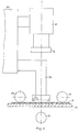
- Figs. 2 and 3 illustrate a scanning system provided with the imaging system according to the invention.
- the scanning system employs, for example, a rectilinear line-scan CCD camera 10, with the scanned line extending in a plane perpendicular to the plane of Fig. 2, and parallel to the plane of Fig. 3.
- the printed-circuit board to be inspected is mounted on the transparent window 24 of a translating stage, with two spring-loaded rollers 26,28 pressing the board against the window 24.
- the stage translates the PC-board 8 in the plane of the paper in Fig. 2, and into the paper, in Fig. 3.
- the plastic Fresnel lens 2 is a narrow slab cut from the central part of the original lens, and held rigidly in a position substantially parallel to the line scanned by the camera by two supporting members 30,32.
- the Fresnel lens 2 is mounted in such a way that its optical axis substantially coincides with that of imaging lens 4.
- Fig. 4 shows schematically how the line-scan camera is used to inspect the entire area of printed-circuit board 8.
- the area 42 sensed by the camera at any particular instant is substantially elongate, its width being typically a thousand times smaller than its length. This length, in turn, is usually much smaller than the length of the printed circuit board to be inspected. Inspection of an extended object therefore entails a relative translation between camera and object, producing the meandering path indicated by the heavy solid line in Fig. 4.
- Translation consists of a continuous motion along an axis perpendicular to the scanned line, followed by a stepwise translation along an axis parallel to the scanned line. This is repeated until the entire area of interest has been sensed.
- the translation step along the board is somewhat shorter than the width of the "swath" cut by the line-scan camera in its pass across the board, so that a slight overlap (not shown) is produced between adjacent "swaths".
- the total area covered by the scan is somewhat larger in width, as well as in length, than the surface area of the printed-circuit board.
- the continuous translation across the printed-circuit board is effected by the movable column 34 (Figs. 2,3) which carries the supporting members 30,32, as well as the camera 10, while the stepwise translation is effected by the above-mentioned translating stage.
- the invention also provides for the software correction of the optical distortion brought about by various imperfections normally found in inexpensive, mass-produced Fresnel lenses.
- This software correction is achieved by a one-time calibration procedure performed for each particular system, a process based on the existence in the system of a precise dimensional benchmark.
- fiducial marks are high-contrast patterns of well defined geometry, e.g., a cross, a circle, a checkerboard pattern, or a grid of lines, etc.
- the patterns are superimposed on the object plane at precisely known locations, and are imaged by the camera.
- the fiducial marks are then detected in the resulting image by suitably processing the camera signal.
- This map may be in the form of a set of correction terms applied for each resolution element, or pixel, in the image.
- the calibration procedure takes advantage of the accurate translatory motion of the scanning mechanisms moving the stage supporting the printed-circuit board, and the column supporting the optical head.
- the fiducial marks are reduced to two mutually perpendicular straight edges, constituted by abrupt transitions between transparent and opaque regions. Rather than using a multitude of fiducial marks, a single target containing the two edges is translated at precisely known steps relative to the camera, using both object stage and column translatory motions. An effective array of fiducial marks is thus synthesized by detecting the edge position in the image signal following each stepwise translation.
- the preferred embodiment offers several advantages over standard techniques; since the translation step between consecutive measurements is variable at will, the technique lends itself readily to systems having variable resolution and or magnification.
- the calibration procedure yields two sets of correction terms applied to each resolution element of the line-scanning camera, in two orthogonal directions.
- the calibration terms are stored in the system's memory, and are used to correct all subsequent camera signals for dimensional errors due to optical-system distortions. That memory section in which the calibration terms are stored is designated as a look-up table.
- the calibration procedure uses two edges which, as above defined, are abrupt transitions between opaque and transparent regions in the object plane.
- One edge, 36 (Fig. 5) should extend substantially parallel to the line scanned by the linear CCD camera 10, which will be designated in the following as the x-axis.
- the other edge, 38 should extend substantially parallel to the scanning direction of the object stage window 24 (in the following, for short, "object stage”), or the y-axis.
- the two edges are provided by a calibration target 40 mountable on the object stage.
- p0 denotes the area sensed by camera element p0, etc., and (x0, y0) is an edge point inside that area.
- the column 34 (Fig. 2) supporting the optical head is now moved along the x-axis by a precisely known amount 1.
- the same edge point (x0,y0) is now sensed by another camera sensor element, p1.
- the process is repeated, each time the optical head is moved by the same amount 1, throughout the entire field-of-view of the camera.
- the interval 1 is suitably chosen to adequately sample the distortion pattern of the optical system.
- the set of camera elements p0, p1, ....p n is plotted against the corresponding translations 0,1,21,...n1.
- all measured points should fall on a straight line. Therefore, a linear regression is performed on the set of points, e.g., by the least-squares method.
- the set of x-axis distortions or deviations from the calculated straight line, such as ⁇ x1, ⁇ x2 in Fig. 6A, suitably interpolated for all intermediate camera sensor elements, is now entered in a look-up table.
- That look-up table is later used to correct all subsequent camera signal data for x-axis distortion, before further processing.
- the foregoing calibration procedure also yields the value of the pixel size, namely the center-to-center spacing between object regions sampled by adjacent camera sensor elements.
- the y-axis distortion is measured by a similar procedure. Referring now to Fig. 7, the object stage and optical head are translated such that the camera senses the edge 36.
- the object stage is now scanned along the y-axis, and the edge position (x0,y0) is calculated from the camera signal for some sensor element q0.
- the optical head is now translated by some small amount s, calculated such that the same edge point, properly accounting for x-axis distortion, is being sensed by another camera sensor element q1.
- the calculation of the appropriate translation is based on the pixel size, computed in the above-mentioned previous step.
- the object stage is scanned in y-direction and the system searches for the new apparent (possibly distorted) edge coordinate (x0,y1). As before, the process is repeated to cover the full width of the camera field-of-view.
- the interval s is chosen to adequately sample the y-axis distortion.
- the resultant set of camera sensor elements q0,q1,q2...q m (this time all equally spaced) is plotted against the corresponding (distorted) y-coordinates y0,y1,y2....y m .
- all y-coordinates should be identical.
- there may be a finite rotational error of the camera i.e., the linear sensor is not perfectly parallel to the x-axis. This effect would tend to make the linear plot somewhat slanted. Any deviation from a straight line is attributed to optical distortion.
- a look-up table representing the y-axis distortions of each sensor element (such as ⁇ y1, ⁇ y2 in Fig. 8A) is prepared and used to correct subsecuent camera signals.
Landscapes
- Physics & Mathematics (AREA)
- General Physics & Mathematics (AREA)
- Analytical Chemistry (AREA)
- Health & Medical Sciences (AREA)
- Life Sciences & Earth Sciences (AREA)
- Chemical & Material Sciences (AREA)
- Optics & Photonics (AREA)
- Biochemistry (AREA)
- General Health & Medical Sciences (AREA)
- Immunology (AREA)
- Pathology (AREA)
- Lenses (AREA)
- Microscoopes, Condenser (AREA)
- Studio Devices (AREA)
- Length Measuring Devices By Optical Means (AREA)
Claims (11)
- Ein telezentrisches Abbildungssystem, umfassend eine Linse, die nahe bei einem Gegenstand (8) befestigbar ist, der abgebildet werden soll, eine Lichtquelle (12) zum Beleuchten des Gegenstands (8) und eine Aperturblende (6), die mindestens in der Nähe des hinteren Brennpunkts der genannten Linse angeordnet ist, dadurch gekennzeichnet, daß die genannte Linse eine Fresnel Linse (2) ist.
- Ein Abbildungssystem, wie in Anspruch 1 beansprucht, in dem die genannte Aperturblende (6) von der Eintrittspupille einer zweiten Abbildungslinse (4) gebildet ist.
- Ein Abbildungssystem wie in Anspruch 1 beansprucht, in dem die genannte Fresnel Linse (2) eine Kunststofflinse ist.
- Ein Abbildungssystem, wie in Anspruch 1 beansprucht, in dem die genannte Fresnel Linse (2) eine im wesentlichen rechteckförmige Form hat, wobei die optische Achse der genannten Linse mindestens ungefähr durch die geometrische Mitte der genannten rechteckigen Form hindurchgeht.
- Ein optisches Untersuchungsgerät vom Linienabtasttyp, das ein telezentrisches Abbildungssystem gemäß Anspruch 1 verwendet, umfassend eine Säule (34) die zur Verschiebungsbewegung fähig ist, einen Gegenstandstisch, der zur Verschiebungsbewegung in einer im wesentlichen zu der Verschiebungsbewegung der genannten Säule (34) senkrechten Richtung fähig ist, ein lichtdurchlässiges Fenster (24) auf dem genannten Gegenstandstisch, eine Vorrichtung (26, 28), um den genannten Gegenstand (8) an dem genannten Fenster (24) anzubringen, eine ausgedehnte Lichtquelle (12) hinter dem genannten Fenster (24), eine Linienabtast-Kamera (10), die an dem Kopf der genannten Säule (34) angebracht ist, eine Objektivlinse (4), die den genannten Gegenstand (8) auf die genannte Sensorebene der genannten Kamera (10) abbilden kann, und eine Feldlinse, die von der genannten Fresnel Linse (2) des telezentrischen Abbildungssystem, optisch koaxial zu der genannten Objektivlinse (4) gebildet ist und sich nahe dem genannten Gegenstand (8) befindet, der abgebildet werden soll, wobei die Aperturblende (6) des genannten telezentrischen Abbildungssystems bei dem hinteren Brennpunkt der genannten Fresnel Linse (2) angeordnet ist und von der Eintrittspupille der genannten abbildenden Objektivlinse (4) gebildet ist.
- Ein optisches Untersuchungsgerät, wie in Anspruch 5 beansprucht, das ferner ein Kalibrierungsziel (40) zur Software-Korrektur der optischen Verzerrungen umfaßt, die durch das genannte telezentrische Abbildungssystem erzeugt werden, wobei das genannte Ziel an dem genannten Gegenstandstisch befestibar ist und mindestens eine Bezugsmarkierung (36, 38) umfaßt, die auf die genannte Linienabtast-Kamera (10) abgebildet werden kann.
- Ein optisches Untersuchungsgerät, wie in Anspruch 6 beansprucht, in dem das genannte Kalibrierungsziel (40) auf dem genannten Gegenstandstisch zwei lineare Bezugsmarkierungen in der Form von zwei Rändern (36, 38) umfaßt, die von plötzlichen Übergängen zwischen lichtundurchlässigen und lichtdurchlässigen Bereichen des genannten Ziels gebildet sind, wobei sich einer der Bezugsränder (36) in der Richtung einer X-Achse erstreckt, die im wesentlichen parallel zu der Abtastlinie der genannten Linienabtast-Kamera ist, und sich der andere Bezugsrand (38) in Richtung einer Y-Achse erstreckt, die im wesentlichen parallel zu der Abtastrichtung des genannten Gegenstandstisches ist.
- Ein Verfahren zur Software-Korrektur der optischen Verzerrung, die durch das telezentrische Abbildungssystem eines optischen Untersuchungsgeräts gemäß Anspruch 5 erzeugt wird, das die Schritte umfaßt:Befestigen eines Kalibrierungsziels (40) an dem Gegenstandstisch des genannten Geräts, das mindestens eine Bezugsmarkierung umfaßt, und Ausführen einer relativen Verschiebung zwischen der Kamera (10) und dem Gegenstandstisch in der Richtung einer ersten und zweiten von zwei sich schneidenden Achsen, bis die genannte Bezugsmarkierung auf der genannten Kamera (10) abgebildet und von ihr erfaßt wird;Berechnen des Kameraelements aus dem von der genannten Kamera (10) erzeugten Signal, auf das die genannte Bezugsmarkierung abgebildet ist, und Ausführen einer relativen Verschiebungsbewegung zwischen der genannten Kamera und dem genannten Gegenstandstisch entlang der genannten ersten Achse mit bestimmten, gleichen und genau bekannten Schritten, und Erfassen der genannten Bezugsmarkierung bei jedem Schritt;Auftragen des derart hergestellten Satzes von Kameraelementen gegen die Abfolge der genannten bestimmten Schritte und Ausführen einer linearen Regression an den derart aufgetragenen Punkten;Herstellen eines Satzes von Abweichungen von der ersten Achse unter Verwendung der derart erhaltenen Regressionslinie und Eingeben der genannten Abweichungen in eine Nachschlagetabelle, die zu verwenden ist, um nachfolgende Kamerasignale zu korrigieren;Ausführen einer kontinuierlichen Verschiebungsbewegung zwischen der genannten Kamera (10) und dem genannten Gegenstandstisch in der Richtung der genannten zweiten Achse, bis die genannte Bezugsmarkierung auf der genannten Kamera abgebildet und von ihr erfaßt wird;Berechnen des Kameralements aus den durch die Kamera erzeugten Signalen, auf das die genannte Bezugsmarkierung abgebildet wird, und der entsprechenden Koordinate entlang der zweiten Achse;Ausführen einer relativen Verschiebungsbewegung zwischen der genannten Kamera und dem genannten Gegenstandstisch in der Richtung der genannten ersten Achse mit bestimmten, gleichen und genau bekannten Schritten;Ausführen einer kontinuierlichen, relativen Verschiebungsbewegung zwischen der genannten Kamera und dem genannten Gegenstandstisch in der Richtung der genannten zweiten Achse, die jeder der genannten Verschiebungen bei der ersten Achse folgt, und Erfassen der genannten Bezugsmarkierung bei jedem Schritt;Auftragen des derart hergestellten Satzes von Kameraelementen gegen die entsprechenden Koordinaten der zweiten Achse, undAusführen einer linearen Regression an den derart aufgetragenen Punkte und Herstellen eines Satzes von Abweichungen von der zweiten Achse unter Verwendung der derart erhaltenen Regressionslinie, und Eingeben der genannten Abweichungen in eine Nachschlagetabelle, die zu verwenden ist, um die nachfolgenden Kamerasignale zu korrigieren.
- Ein Verfahren, wie in Anspruch 8 beansprucht, in dem das genannte Kalibrierungsziel (40) auf dem genannten Gegenstandstisch zwei lineare Bezugsmarkierungen in der Form von zwei Rändern (36, 38) umfaßt, die von plötzlichen Übergängen zwischen lichtundurchlässigen und lichtdurchlässigen Bereichen des genannten Ziels gebildet sind, wobei sich einer der Bezugsränder (36) in der Richtung der genannten ersten Achse erstreckt, die im wesentlichen parallel zu der Abtastlinie der genannten Linienabtast-Kamera (10) ist, und sich der andere Bezugsrand (38) in Richtung der genannten zweiten Achse erstreckt, die im wesentlichen parallel zu der Abtastrichtung des genannten Gegenstandstisches ist.
- Ein Verfahren, wie in Anspruch 9 beansprucht, in dem der von der genannten Kamera (10) abgetastete Bezugsrand bei einer Abtastung auf der ersten Achse der genannte zweite Bezugsrand (38) ist, und der von der genannten Kamera bei einer Abtastung auf der zweiten Achse abgetastete Bezugsrand der genannte erste Bezugsrand (36) ist.
- Ein Verfahren, wie in Anspruch 8 beansprucht, in dem die genannte erste Achse eine X-Achse ist, die sich in Richtung der Abtastlinie der genannten Linienabtast-Kamera (10) erstreckt, und die genannte zweite Achse eine Y-Achse ist, die sich in einer zu der genannten X-Achse senkrechten Richtung erstreckt.
Applications Claiming Priority (2)
| Application Number | Priority Date | Filing Date | Title |
|---|---|---|---|
| IL85862 | 1988-03-24 | ||
| IL85862A IL85862A (en) | 1988-03-24 | 1988-03-24 | Telecentric imaging system |
Publications (3)
| Publication Number | Publication Date |
|---|---|
| EP0335559A2 EP0335559A2 (de) | 1989-10-04 |
| EP0335559A3 EP0335559A3 (de) | 1991-08-28 |
| EP0335559B1 true EP0335559B1 (de) | 1996-02-28 |
Family
ID=11058704
Family Applications (1)
| Application Number | Title | Priority Date | Filing Date |
|---|---|---|---|
| EP89302766A Expired - Lifetime EP0335559B1 (de) | 1988-03-24 | 1989-03-21 | Telezentrisch abbildendes System |
Country Status (5)
| Country | Link |
|---|---|
| US (1) | US5008743A (de) |
| EP (1) | EP0335559B1 (de) |
| AT (1) | ATE134776T1 (de) |
| DE (1) | DE68925744T2 (de) |
| IL (1) | IL85862A (de) |
Families Citing this family (43)
| Publication number | Priority date | Publication date | Assignee | Title |
|---|---|---|---|---|
| CH679428A5 (de) * | 1990-02-02 | 1992-02-14 | Peyer Ag Siegfried | |
| IL99823A0 (en) * | 1990-11-16 | 1992-08-18 | Orbot Instr Ltd | Optical inspection method and apparatus |
| DE4208635C1 (en) * | 1992-03-18 | 1993-07-22 | Jenoptik Gmbh, O-6900 Jena, De | Telecentric objective lens with double Gaussian objective - couples lens contents into image conducting fibres with higher illuminating strength at picture edges |
| US5517234A (en) * | 1993-10-26 | 1996-05-14 | Gerber Systems Corporation | Automatic optical inspection system having a weighted transition database |
| US5461228A (en) * | 1994-04-07 | 1995-10-24 | Owens-Brockway Glass Container Inc. | Optical inspection of container dimensional parameters using a telecentric lens |
| US5610391A (en) * | 1994-08-25 | 1997-03-11 | Owens-Brockway Glass Container Inc. | Optical inspection of container finish dimensional parameters |
| US5880772A (en) * | 1994-10-11 | 1999-03-09 | Daimlerchrysler Corporation | Machine vision image data acquisition system |
| JP3753758B2 (ja) * | 1995-05-24 | 2006-03-08 | フジノン株式会社 | 液晶ビデオプロジェクタ |
| DE29510334U1 (de) * | 1995-06-26 | 1995-10-26 | AQS Dimensionale Meßtechnik GmbH, Hallein/Salzburg | System zur zweidimensionalen Vermessung planer Objekte |
| EP0858055B1 (de) * | 1995-09-29 | 2005-10-12 | Wincor Nixdorf International GmbH | Vorrichtung zur Vermessung von Poststücken |
| US5610710A (en) * | 1996-05-28 | 1997-03-11 | International Business Machines Corporation | Dual mode illumination system for optical inspection |
| US5805277A (en) * | 1997-08-06 | 1998-09-08 | Coherent, Inc. | Portable laser power measuring apparatus |
| US6072898A (en) | 1998-01-16 | 2000-06-06 | Beaty; Elwin M. | Method and apparatus for three dimensional inspection of electronic components |
| US6151117A (en) * | 1999-08-30 | 2000-11-21 | Xerox Corporation | Optical sensor with telecentric optics |
| FI114743B (fi) | 1999-09-28 | 2004-12-15 | Ekspansio Engineering Ltd Oy | Telesentrisellä periaatteella toimiva laitteisto ja menetelmä |
| US6256095B1 (en) | 2000-01-21 | 2001-07-03 | Owens-Brockway Glass Container Inc. | Container sealing surface area inspection |
| IL135419A0 (en) | 2000-04-02 | 2001-05-20 | Orbotech Ltd | Post-etch inspection system |
| DE10019486A1 (de) | 2000-04-19 | 2001-10-31 | Siemens Ag | Anordnung zur Inspektion von Objektoberflächen |
| US7167583B1 (en) | 2000-06-28 | 2007-01-23 | Landrex Technologies Co., Ltd. | Image processing system for use with inspection systems |
| US6552783B1 (en) | 2000-06-28 | 2003-04-22 | Teradyne, Inc. | Optical system |
| EP1213568B1 (de) * | 2000-12-08 | 2005-12-28 | Gretag-Macbeth AG | Vorrichtung zur bildelementweisen Ausmessung eines flächigen Messobjekts |
| EP1213569B1 (de) * | 2000-12-08 | 2006-05-17 | Gretag-Macbeth AG | Vorrichtung zur bildelementweisen Ausmessung eines flächigen Messobjekts |
| EP1220596A1 (de) | 2000-12-29 | 2002-07-03 | Icos Vision Systems N.V. | Verfahren und Einrichtung zur Lageerfassung der Anschlusskontakte elektronischer Bauelemente |
| US6700658B2 (en) | 2001-10-05 | 2004-03-02 | Electro Scientific Industries, Inc. | Method and apparatus for circuit pattern inspection |
| US6892013B2 (en) * | 2003-01-15 | 2005-05-10 | Negevtech Ltd. | Fiber optical illumination system |
| US7525659B2 (en) * | 2003-01-15 | 2009-04-28 | Negevtech Ltd. | System for detection of water defects |
| US7486861B2 (en) * | 2003-01-15 | 2009-02-03 | Negevtech Ltd. | Fiber optical illumination system |
| TWI258583B (en) * | 2003-01-30 | 2006-07-21 | Test Research Inc | Device and method for optical detection of printed circuit board |
| DE602005004332T2 (de) | 2004-06-17 | 2009-01-08 | Cadent Ltd. | Verfahren zum Bereitstellen von Daten im Zusammenhang mit der Mundhöhle |
| WO2006006148A2 (en) * | 2004-07-12 | 2006-01-19 | Negevtech Ltd. | Multi mode inspection method and apparatus |
| US20060012781A1 (en) * | 2004-07-14 | 2006-01-19 | Negevtech Ltd. | Programmable spatial filter for wafer inspection |
| US7813541B2 (en) * | 2005-02-28 | 2010-10-12 | Applied Materials South East Asia Pte. Ltd. | Method and apparatus for detecting defects in wafers |
| US7804993B2 (en) * | 2005-02-28 | 2010-09-28 | Applied Materials South East Asia Pte. Ltd. | Method and apparatus for detecting defects in wafers including alignment of the wafer images so as to induce the same smear in all images |
| DE102005043112A1 (de) * | 2005-09-10 | 2007-03-15 | E. Zoller GmbH & Co. KG Einstell- und Messgeräte | Werkzeugmess- und/oder Werkzeugeinstellgerät |
| US8031931B2 (en) * | 2006-04-24 | 2011-10-04 | Applied Materials South East Asia Pte. Ltd. | Printed fourier filtering in optical inspection tools |
| US7714998B2 (en) * | 2006-11-28 | 2010-05-11 | Applied Materials South East Asia Pte. Ltd. | Image splitting in optical inspection systems |
| US7719674B2 (en) * | 2006-11-28 | 2010-05-18 | Applied Materials South East Asia Pte. Ltd. | Image splitting in optical inspection systems |
| US20130120557A1 (en) * | 2011-11-14 | 2013-05-16 | Microscan Systems, Inc. | Part inspection system |
| EP3002549B1 (de) | 2012-06-08 | 2017-05-03 | VICI & C.- S.p.A. | Maschine und verfahren zur optischen messung |
| WO2015009350A1 (en) * | 2013-07-16 | 2015-01-22 | Leeo, Inc. | Electronic device with environmental monitoring |
| US9675430B2 (en) | 2014-08-15 | 2017-06-13 | Align Technology, Inc. | Confocal imaging apparatus with curved focal surface |
| CN110568598A (zh) * | 2019-08-29 | 2019-12-13 | 深圳市灿锐科技有限公司 | 一种低成本超大口径的物方远心光学系统 |
| CN115931869B (zh) * | 2022-11-22 | 2025-07-11 | 凌云光技术股份有限公司 | 一种用于极片检测的高速前馈系统及方法 |
Family Cites Families (6)
| Publication number | Priority date | Publication date | Assignee | Title |
|---|---|---|---|---|
| US3637282A (en) * | 1970-02-21 | 1972-01-25 | Olympus Optical Co | Elongated variable magnification optical system having selectively interchangeable lenses |
| US3761184A (en) * | 1972-02-07 | 1973-09-25 | Itek Corp | Wide angle, narrow bandwidth laser detection system |
| US3994583A (en) * | 1974-02-25 | 1976-11-30 | Hutchins Iv Thomas B | Noncontacting method and apparatus for monitoring the speed and travel of a moving article |
| US4582393A (en) * | 1984-05-04 | 1986-04-15 | Bright & Morning Star, Ca. | Polarizing optical stereoscopic system and eyepiece using triangular prisms |
| US4695892A (en) * | 1986-06-27 | 1987-09-22 | The United States Of America As Represented By The Secretary Of The Army | Method for determining the angular dimensions of a scene recorded by a video system |
| DE3641258A1 (de) * | 1986-12-03 | 1988-06-16 | Sick Optik Elektronik Erwin | Bildaufnahmevorrichtung |
-
1988
- 1988-03-24 IL IL85862A patent/IL85862A/xx not_active IP Right Cessation
-
1989
- 1989-03-17 US US07/324,716 patent/US5008743A/en not_active Expired - Lifetime
- 1989-03-21 AT AT89302766T patent/ATE134776T1/de not_active IP Right Cessation
- 1989-03-21 DE DE68925744T patent/DE68925744T2/de not_active Expired - Fee Related
- 1989-03-21 EP EP89302766A patent/EP0335559B1/de not_active Expired - Lifetime
Also Published As
| Publication number | Publication date |
|---|---|
| IL85862A (en) | 1993-01-14 |
| EP0335559A2 (de) | 1989-10-04 |
| EP0335559A3 (de) | 1991-08-28 |
| US5008743A (en) | 1991-04-16 |
| ATE134776T1 (de) | 1996-03-15 |
| IL85862A0 (en) | 1988-09-30 |
| DE68925744T2 (de) | 1996-09-19 |
| DE68925744D1 (de) | 1996-04-04 |
Similar Documents
| Publication | Publication Date | Title |
|---|---|---|
| EP0335559B1 (de) | Telezentrisch abbildendes System | |
| JP3161602B2 (ja) | 三次元スキャニングシステム | |
| EP0397672B1 (de) | Verfahren und vorrichtung zur schnellen, hochauflösenden, dreidimensionalen abbildung eines gegenstandes an einer untersuchungsstation | |
| US6067165A (en) | Position calibrating method for optical measuring apparatus | |
| US7002676B2 (en) | Appearance inspection apparatus and the method of inspecting the same | |
| US4677302A (en) | Optical system for inspecting printed circuit boards wherein a ramp filter is disposed between reflected beam and photodetector | |
| KR950012572A (ko) | 노광 방법 | |
| JP2510786B2 (ja) | 物体の形状検出方法及びその装置 | |
| US6819789B1 (en) | Scaling and registration calibration especially in printed circuit board fabrication | |
| US4641257A (en) | Measurement method and apparatus for alignment | |
| US12169370B2 (en) | Exposure control in photolithographic direct exposure methods for manufacturing circuit boards or circuits | |
| US5648853A (en) | System for inspecting pin grid arrays | |
| US6396589B1 (en) | Apparatus and method for measuring three-dimensional shape of object | |
| JP3715377B2 (ja) | 物体形状測定装置 | |
| US7265881B2 (en) | Method and apparatus for measuring assembly and alignment errors in sensor assemblies | |
| KR0170783B1 (ko) | 표면 광학 주사 장치 | |
| KR20060132579A (ko) | 이미징 시스템의 초점을 결정하기 위한 방법 및 장치 | |
| JP2024080670A (ja) | 光三角測量に基づく3次元撮像のための撮像システムの較正において使用するための実世界および画像センサー対応点の提供 | |
| US5631738A (en) | Laser ranging system having reduced sensitivity to surface defects | |
| JPS62272107A (ja) | 実装部品検査方法 | |
| JP3209186B2 (ja) | 露光装置及び方法 | |
| JPS608724B2 (ja) | 検出装置 | |
| JP3209189B2 (ja) | 露光装置及び方法 | |
| JPH0126587B2 (de) | ||
| KR20020024655A (ko) | 부품 검사 장치 |
Legal Events
| Date | Code | Title | Description |
|---|---|---|---|
| PUAI | Public reference made under article 153(3) epc to a published international application that has entered the european phase |
Free format text: ORIGINAL CODE: 0009012 |
|
| AK | Designated contracting states |
Kind code of ref document: A2 Designated state(s): AT BE CH DE ES FR GB GR IT LI LU NL SE |
|
| PUAL | Search report despatched |
Free format text: ORIGINAL CODE: 0009013 |
|
| AK | Designated contracting states |
Kind code of ref document: A3 Designated state(s): AT BE CH DE ES FR GB GR IT LI LU NL SE |
|
| 17P | Request for examination filed |
Effective date: 19920131 |
|
| RAP1 | Party data changed (applicant data changed or rights of an application transferred) |
Owner name: ORBOTECH LTD |
|
| 17Q | First examination report despatched |
Effective date: 19940204 |
|
| GRAA | (expected) grant |
Free format text: ORIGINAL CODE: 0009210 |
|
| AK | Designated contracting states |
Kind code of ref document: B1 Designated state(s): AT BE CH DE ES FR GB GR IT LI LU NL SE |
|
| PG25 | Lapsed in a contracting state [announced via postgrant information from national office to epo] |
Ref country code: IT Free format text: LAPSE BECAUSE OF FAILURE TO SUBMIT A TRANSLATION OF THE DESCRIPTION OR TO PAY THE FEE WITHIN THE PRE;WARNING: LAPSES OF ITALIAN PATENTS WITH EFFECTIVE DATE BEFORE 2007 MAY HAVE OCCURRED AT ANY TIME BEFORE 2007. THE CORRECT EFFECTIVE DATE MAY BE DIFFERENT FROM THE ONE RECORDED.SCRIBED TIME-LIMIT Effective date: 19960228 Ref country code: BE Effective date: 19960228 Ref country code: LI Free format text: LAPSE BECAUSE OF FAILURE TO SUBMIT A TRANSLATION OF THE DESCRIPTION OR TO PAY THE FEE WITHIN THE PRESCRIBED TIME-LIMIT Effective date: 19960228 Ref country code: GR Free format text: LAPSE BECAUSE OF FAILURE TO SUBMIT A TRANSLATION OF THE DESCRIPTION OR TO PAY THE FEE WITHIN THE PRESCRIBED TIME-LIMIT Effective date: 19960228 Ref country code: CH Free format text: LAPSE BECAUSE OF FAILURE TO SUBMIT A TRANSLATION OF THE DESCRIPTION OR TO PAY THE FEE WITHIN THE PRESCRIBED TIME-LIMIT Effective date: 19960228 Ref country code: ES Free format text: THE PATENT HAS BEEN ANNULLED BY A DECISION OF A NATIONAL AUTHORITY Effective date: 19960228 Ref country code: NL Free format text: LAPSE BECAUSE OF FAILURE TO SUBMIT A TRANSLATION OF THE DESCRIPTION OR TO PAY THE FEE WITHIN THE PRESCRIBED TIME-LIMIT Effective date: 19960228 Ref country code: AT Effective date: 19960228 |
|
| REF | Corresponds to: |
Ref document number: 134776 Country of ref document: AT Date of ref document: 19960315 Kind code of ref document: T |
|
| PG25 | Lapsed in a contracting state [announced via postgrant information from national office to epo] |
Ref country code: LU Free format text: LAPSE BECAUSE OF NON-PAYMENT OF DUE FEES Effective date: 19960331 |
|
| REF | Corresponds to: |
Ref document number: 68925744 Country of ref document: DE Date of ref document: 19960404 |
|
| PG25 | Lapsed in a contracting state [announced via postgrant information from national office to epo] |
Ref country code: SE Effective date: 19960531 |
|
| ET | Fr: translation filed | ||
| NLV1 | Nl: lapsed or annulled due to failure to fulfill the requirements of art. 29p and 29m of the patents act | ||
| REG | Reference to a national code |
Ref country code: CH Ref legal event code: PL |
|
| PLBE | No opposition filed within time limit |
Free format text: ORIGINAL CODE: 0009261 |
|
| STAA | Information on the status of an ep patent application or granted ep patent |
Free format text: STATUS: NO OPPOSITION FILED WITHIN TIME LIMIT |
|
| 26N | No opposition filed | ||
| REG | Reference to a national code |
Ref country code: GB Ref legal event code: IF02 |
|
| PGFP | Annual fee paid to national office [announced via postgrant information from national office to epo] |
Ref country code: FR Payment date: 20030310 Year of fee payment: 15 |
|
| PGFP | Annual fee paid to national office [announced via postgrant information from national office to epo] |
Ref country code: GB Payment date: 20030319 Year of fee payment: 15 |
|
| PGFP | Annual fee paid to national office [announced via postgrant information from national office to epo] |
Ref country code: DE Payment date: 20030403 Year of fee payment: 15 |
|
| PG25 | Lapsed in a contracting state [announced via postgrant information from national office to epo] |
Ref country code: GB Free format text: LAPSE BECAUSE OF NON-PAYMENT OF DUE FEES Effective date: 20040321 |
|
| PG25 | Lapsed in a contracting state [announced via postgrant information from national office to epo] |
Ref country code: DE Free format text: LAPSE BECAUSE OF NON-PAYMENT OF DUE FEES Effective date: 20041001 |
|
| GBPC | Gb: european patent ceased through non-payment of renewal fee |
Effective date: 20040321 |
|
| PG25 | Lapsed in a contracting state [announced via postgrant information from national office to epo] |
Ref country code: FR Free format text: LAPSE BECAUSE OF NON-PAYMENT OF DUE FEES Effective date: 20041130 |
|
| REG | Reference to a national code |
Ref country code: FR Ref legal event code: ST |
|
| P01 | Opt-out of the competence of the unified patent court (upc) registered |
Effective date: 20230525 |