EP0335577B1 - Système transducteur ultrasonore - Google Patents
Système transducteur ultrasonore Download PDFInfo
- Publication number
- EP0335577B1 EP0335577B1 EP89302846A EP89302846A EP0335577B1 EP 0335577 B1 EP0335577 B1 EP 0335577B1 EP 89302846 A EP89302846 A EP 89302846A EP 89302846 A EP89302846 A EP 89302846A EP 0335577 B1 EP0335577 B1 EP 0335577B1
- Authority
- EP
- European Patent Office
- Prior art keywords
- lines
- delay
- echo signals
- delay line
- line
- Prior art date
- Legal status (The legal status is an assumption and is not a legal conclusion. Google has not performed a legal analysis and makes no representation as to the accuracy of the status listed.)
- Expired - Lifetime
Links
- 230000004044 response Effects 0.000 claims description 22
- 238000002592 echocardiography Methods 0.000 claims description 3
- 238000000034 method Methods 0.000 description 14
- 230000006870 function Effects 0.000 description 13
- 230000008569 process Effects 0.000 description 10
- 230000001934 delay Effects 0.000 description 9
- 238000010586 diagram Methods 0.000 description 9
- 230000015654 memory Effects 0.000 description 8
- 239000012530 fluid Substances 0.000 description 5
- 239000008280 blood Substances 0.000 description 4
- 210000004369 blood Anatomy 0.000 description 4
- 230000017531 blood circulation Effects 0.000 description 4
- 210000001765 aortic valve Anatomy 0.000 description 3
- 230000006872 improvement Effects 0.000 description 3
- 230000003139 buffering effect Effects 0.000 description 2
- 230000015556 catabolic process Effects 0.000 description 2
- 230000007423 decrease Effects 0.000 description 2
- 238000006731 degradation reaction Methods 0.000 description 2
- 238000003745 diagnosis Methods 0.000 description 2
- 230000036316 preload Effects 0.000 description 2
- 210000005241 right ventricle Anatomy 0.000 description 2
- 230000001052 transient effect Effects 0.000 description 2
- 210000000709 aorta Anatomy 0.000 description 1
- 210000001124 body fluid Anatomy 0.000 description 1
- 239000013078 crystal Substances 0.000 description 1
- 230000003111 delayed effect Effects 0.000 description 1
- 238000003384 imaging method Methods 0.000 description 1
- 210000005246 left atrium Anatomy 0.000 description 1
- 210000005240 left ventricle Anatomy 0.000 description 1
- 210000004072 lung Anatomy 0.000 description 1
- 210000004115 mitral valve Anatomy 0.000 description 1
- 238000007781 pre-processing Methods 0.000 description 1
- 230000009467 reduction Effects 0.000 description 1
- 210000005245 right atrium Anatomy 0.000 description 1
- 238000012163 sequencing technique Methods 0.000 description 1
- 238000004154 testing of material Methods 0.000 description 1
- 230000001131 transforming effect Effects 0.000 description 1
- 210000000591 tricuspid valve Anatomy 0.000 description 1
- 230000001960 triggered effect Effects 0.000 description 1
- 210000001835 viscera Anatomy 0.000 description 1
Images


Classifications
-
- G—PHYSICS
- G10—MUSICAL INSTRUMENTS; ACOUSTICS
- G10K—SOUND-PRODUCING DEVICES; METHODS OR DEVICES FOR PROTECTING AGAINST, OR FOR DAMPING, NOISE OR OTHER ACOUSTIC WAVES IN GENERAL; ACOUSTICS NOT OTHERWISE PROVIDED FOR
- G10K11/00—Methods or devices for transmitting, conducting or directing sound in general; Methods or devices for protecting against, or for damping, noise or other acoustic waves in general
- G10K11/18—Methods or devices for transmitting, conducting or directing sound
- G10K11/26—Sound-focusing or directing, e.g. scanning
- G10K11/34—Sound-focusing or directing, e.g. scanning using electrical steering of transducer arrays, e.g. beam steering
- G10K11/341—Circuits therefor
- G10K11/345—Circuits therefor using energy switching from one active element to another
-
- G—PHYSICS
- G01—MEASURING; TESTING
- G01N—INVESTIGATING OR ANALYSING MATERIALS BY DETERMINING THEIR CHEMICAL OR PHYSICAL PROPERTIES
- G01N29/00—Investigating or analysing materials by the use of ultrasonic, sonic or infrasonic waves; Visualisation of the interior of objects by transmitting ultrasonic or sonic waves through the object
- G01N29/04—Analysing solids
- G01N29/06—Visualisation of the interior, e.g. acoustic microscopy
- G01N29/0609—Display arrangements, e.g. colour displays
-
- G—PHYSICS
- G01—MEASURING; TESTING
- G01S—RADIO DIRECTION-FINDING; RADIO NAVIGATION; DETERMINING DISTANCE OR VELOCITY BY USE OF RADIO WAVES; LOCATING OR PRESENCE-DETECTING BY USE OF THE REFLECTION OR RERADIATION OF RADIO WAVES; ANALOGOUS ARRANGEMENTS USING OTHER WAVES
- G01S15/00—Systems using the reflection or reradiation of acoustic waves, e.g. sonar systems
- G01S15/88—Sonar systems specially adapted for specific applications
- G01S15/89—Sonar systems specially adapted for specific applications for mapping or imaging
- G01S15/8906—Short-range imaging systems; Acoustic microscope systems using pulse-echo techniques
- G01S15/8909—Short-range imaging systems; Acoustic microscope systems using pulse-echo techniques using a static transducer configuration
- G01S15/8915—Short-range imaging systems; Acoustic microscope systems using pulse-echo techniques using a static transducer configuration using a transducer array
- G01S15/8918—Short-range imaging systems; Acoustic microscope systems using pulse-echo techniques using a static transducer configuration using a transducer array the array being linear
-
- G—PHYSICS
- G01—MEASURING; TESTING
- G01S—RADIO DIRECTION-FINDING; RADIO NAVIGATION; DETERMINING DISTANCE OR VELOCITY BY USE OF RADIO WAVES; LOCATING OR PRESENCE-DETECTING BY USE OF THE REFLECTION OR RERADIATION OF RADIO WAVES; ANALOGOUS ARRANGEMENTS USING OTHER WAVES
- G01S15/00—Systems using the reflection or reradiation of acoustic waves, e.g. sonar systems
- G01S15/88—Sonar systems specially adapted for specific applications
- G01S15/89—Sonar systems specially adapted for specific applications for mapping or imaging
- G01S15/8906—Short-range imaging systems; Acoustic microscope systems using pulse-echo techniques
- G01S15/8979—Combined Doppler and pulse-echo imaging systems
-
- G—PHYSICS
- G01—MEASURING; TESTING
- G01S—RADIO DIRECTION-FINDING; RADIO NAVIGATION; DETERMINING DISTANCE OR VELOCITY BY USE OF RADIO WAVES; LOCATING OR PRESENCE-DETECTING BY USE OF THE REFLECTION OR RERADIATION OF RADIO WAVES; ANALOGOUS ARRANGEMENTS USING OTHER WAVES
- G01S7/00—Details of systems according to groups G01S13/00, G01S15/00, G01S17/00
- G01S7/52—Details of systems according to groups G01S13/00, G01S15/00, G01S17/00 of systems according to group G01S15/00
- G01S7/52017—Details of systems according to groups G01S13/00, G01S15/00, G01S17/00 of systems according to group G01S15/00 particularly adapted to short-range imaging
- G01S7/52046—Techniques for image enhancement involving transmitter or receiver
-
- G—PHYSICS
- G01—MEASURING; TESTING
- G01S—RADIO DIRECTION-FINDING; RADIO NAVIGATION; DETERMINING DISTANCE OR VELOCITY BY USE OF RADIO WAVES; LOCATING OR PRESENCE-DETECTING BY USE OF THE REFLECTION OR RERADIATION OF RADIO WAVES; ANALOGOUS ARRANGEMENTS USING OTHER WAVES
- G01S7/00—Details of systems according to groups G01S13/00, G01S15/00, G01S17/00
- G01S7/52—Details of systems according to groups G01S13/00, G01S15/00, G01S17/00 of systems according to group G01S15/00
- G01S7/52017—Details of systems according to groups G01S13/00, G01S15/00, G01S17/00 of systems according to group G01S15/00 particularly adapted to short-range imaging
- G01S7/52085—Details related to the ultrasound signal acquisition, e.g. scan sequences
-
- G—PHYSICS
- G01—MEASURING; TESTING
- G01N—INVESTIGATING OR ANALYSING MATERIALS BY DETERMINING THEIR CHEMICAL OR PHYSICAL PROPERTIES
- G01N2291/00—Indexing codes associated with group G01N29/00
- G01N2291/02—Indexing codes associated with the analysed material
- G01N2291/028—Material parameters
- G01N2291/0289—Internal structure, e.g. defects, grain size, texture
Definitions
- This invention relates to ultrasonic transducer systems and more particularly to such systems utilizing a reconfigurable summing delay line to achieve selected processing of echo signals from ultrasonic transducer elements.
- Ultrasonic transducer systems are finding increasing applications in such fields as material testing, product testing and analysis, medical diagnosis, and other medical functions.
- Such systems may provide image data which is displayed on a cathode ray tube or other suitable display to provide dynamic images of the heart, lungs, or other internal organs, and may also be operated in a Doppler or color-flow mode to indicate the direction and velocity of flow at a particular point of blood or other selected bodily fluid.
- the image appearing on the display may, for example, be in one color when the blood or other fluid is flowing in one direction, and in a contrasting color when the blood or fluid is flowing in the opposite direction.
- the intensity of the color indicates the rate of fluid flow in the indicated direction at the point.
- Many systems are adapted to simultaneously provide both image and color flow data.
- An example of such a system is the Hewlett Packard Ultrasonic Scanner Model No. 77020AC revision K.
- a packet of lines for example from four to sixteen scan lines, may be required to provide the data necessary to produce a Doppler color flow image of blood or other fluid flow at the point.
- Such means should also not interfere with the resolution of image data which may be generated concurrently with the color-flow data.
- a particular problem in this regard is the delay line which may be utilized to sum the received echo signals from the transducer elements.
- the delay line is required because the echo wave front does not strike all of the transducer elements at the same time, resulting in the echo signals from the various transducer elements being out of synchronization.
- the received echo signals are applied to taps on the delay line in a manner such as to compensate for the variable times at which the signals are received, resulting in the summing of comparable points sensed by each of the transducer elements.
- the delays between taps on the delay line to which the received signals are applied remain constant, this results in the image being out of focus for the deeper points.
- the resulting transient may cause noise, and thus distortion of the image.
- the delays are either selected for a particular depth with the image being slightly out of focus at other depths, or an average value is selected for the delays which results in the images being increasingly out of focus at near and far depths.
- US-A-4 528 854 discloses an ultrasonic transducer system comprising: a plurality of ultrasonic transducer elements; means for transmitting ultrasonic signals from said elements to a selected target; means for receiving ultrasonic echo signals from said elements; tapped delay line means adapted to sum the received echo signals in a predetermined manner; means for utilising an output of the delay line; means to display a representation of the received echo signals; and means for controlling adapted to cause either serial processing or parallel processing of echo signals.
- the system can only be used with a single type of echo signal. Thus, it can not be used for combined image and colour flow operation.
- the invention provides an ultrasonic transducer system comprising: a plurality of ultrasonic transducer elements; means for transmitting ultrasonic signals from said elements to a selected target; means for receiving ultrasonic echo signals from said elements; tapped delay line means adapted to sum the received echo signals in a predetermined manner; means for utilising an output of the delay line; means to display a representation of the received echo signals; and means for controlling adapted to cause either serial processing or parallel processing of echo signals, characterised in that said means for transmitting is adapted to transmit at least two different types of ultrasonic signal, and in that said means for controlling is adapted to cause serial processing of first echo signals received in response to one type of transmitted signal and parallel processing of second echo signals received in response to a second type of transmitted signal.
- This arrangement permits two separate echo signals to be obtained simultaneously from a single element. This increases the frame rate for a given size of colour flow packet.
- an ultrasonic transducer system includes a plurality of ultrasonic transducer elements, a means for transmitting at least two different types of ultrasonic scan lines, for example, image lines and color flow lines, from the elements, a means for receiving ultrasonic echo signals from the elements in response to the different types of lines, a tapped delay line adapted to sum the received echo signals in a predetermined manner, and a means for utilizing an output of the delay line to display a representation of echo signals received in response to each type of transmitted line.
- the delay line may be configured as a single serial line when echo signals responsive to image lines are being summed, and may be configured as at least two parallel lines when echo signals responsive to color-flow lines are being summed.
- echo signals from selected elements may be applied to one of the lines and echo signals from the other elements applied to the other of the lines.
- echo signals received from at least selected ones of the elements in response to color flow lines be applied as inputs at selected points on both delay lines of the parallel pair. If the delay profiles in the two lines differ slightly, two separate echo signals may be obtained simultaneously from a single element and a single scan line, permitting a substantial improvement in the frame rate of the system for a given size of color-flow packet.
- a packet serializer may be provided to organize the information received from the delay lines, and provide such information to a color-flow processor as required.
- Switch means may be provided for reconfiguring the delay line, the switch means being operated in response to stored settings from a suitable storing means.
- a tapped delay line means is provided in an ultrasonic transducer system which means is adapted to sum the received echo signals in a manner such as to compensate for differences in time at which echo signals are received at the elements.
- a means is provided for utilizing the output of the delay line means to display a representation of the received echo signals, and means are provided for controlling the configuration of the delay line means in response to selected system characteristics.
- the delay line means may be controlled to cause serial processing or parallel processing of received echo signals.
- the delay line means may, for example, be configured so as to act as a means for dynamically focussing the system to the beam depth from which echos are being received. The configuring of the delay line may be accomplished through switch means which are set in response to selected system characteristics.
- Invention also resides in the method of improving the frame rate in such ultrasonic transducer systems by utilizing the delay line to serially process image data and to parallel process color-flow data, the delay line being dynamically reconfigurable to accomplish this objective.
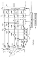
- Fig. 1 is a schematic block diagram of an ultrasonic transducer system incorporating the teachings of this invention.
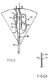
- Fig. 2 illustrates an image of the type obtainable with a system of the type shown in Fig. 1.
- Fig 2A illustrates how two points are obtained during a single scan when in a parallel mode.
- Fig. 3 is a more detailed schematic block diagram of a reconfigurable delay line circuit suitable for use with the embodiment of the invention shown in Fig. 1.
- Fig. 4 is a schematic diagram of an exemplary delay line suitable for use in practicing the teachings of this invention.
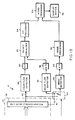
- Fig 5. is a schematic diagram of a packet serializer suitable for use with the embodiment of the invention shown in Fig. 1.
- Fig. 6 is a schematic diagram of an input address sequencer suitable for use in the packet serializer of Fig. 5.
- Fig. 7 is a schematic diagram of an output address sequencer suitable for use in the packet serializer of Fig. 5.
- Fig. 8 is a diagram illustrating the storage and readout of data in a RAM of the packet serializer of Fig. 5.
- Fig. 1 shows the ultrasonic transducer system of this invention being utilized to scan the heart 12 of a person 14. It should, however, be understood that while, in the discussion to follow, the invention will be described with respect to a medical system, the invention is in no way to be construed as being limited to such applications.
- the ultrasonic transducer system 10 includes a plurality of ultrasonic transducer elements 16.
- Each of the transducer elements may, for example, be a thin piece of piezoelectric crystal. In exemplary medical applications there may be 64 or 128 such elements.
- Each transducer 16 is triggered by a signal from a transmitter 18 which is applied to the transducer element through a suitable interface circuit 20 which element protects the receiver 22 for the element and performs an interface function.
- the timing and sequencing for the triggering of transducer elements 16 are selectively controlled to control, for example, the focusing of the scan line..
- the outputs from the other half of the receivers, receivers 22M+1 through 22N, are applied as the second set of inputs to switching circuit 32.
- switching circuit 32 is set as shown in Fig. 1, the echo signals from receivers 22M+1 through 22N are applied through the switching circuit to the corresponding mixers 28M+1 through 28N.
- the switches 32 are transferred from the positions shown in Fig. 1 to their alternate position, the output from receiver 22A is applied in parallel to mixer 28A and to mixer 28M+1, the output from receiver 22B is applied in parallel to mixers 28B and 28M+2, and so on, with the output from receiver 22M being applied in parallel to both mixers 28M and 28N.
- the switches 32 are in this alternate position, the outputs from receivers 22M+1 - 22N are not utilized.
- the other input to each of the mixers 28A - 28N is a signal of controlled phase from control circuit 34 which functions in a manner known in the art to align the phases of the received echo signals, thus compensating in part for the slight variations which occur in the time, and thus the phase, at which the echo signals from a given point in the target are received at transducers 16.
- the outputs from the mixers 28 are applied to tap sequencer 37 in delay line circuit 36.
- the tap sequence determines, in a manner known in the art, the tap or taps on reconfigurable tapped delay line 38 which each mixer output is applied to.
- Delay line 38 is used to sum the echo signals received from the mixers in a manner such as to align the amplitude envelopes of these signals.
- the tap sequencer may apply signals received from transducers at the same distance from the target point to the same delay line tap, the inputs to the taps being aligned in a manner such that inputs received from elements nearer the target point are delayed more than the inputs received from elements farther from the target point.
- the output from delay line element DY on line 41 is connected as the input to color flow detector 42 and as one input to switch 44.
- the output from switch 44 is connected as the input to image detector 46.
- the output from delay line element DX on line 43 is connected as the input to color flow detector 48 and is the other input to switch 44.
- the detectors 42, 46 and 48 operate in a standard fashion to process the summed echo signals received from a given point by transducers 16 into analog voltage signals.
- the output from image detector 46 is applied through an analog-to-digital converter 50 to a digital image processor 52 which formats a received signal in standard fashion for application to video processor 54 which controls the display device 56.
- Display device 56 may, for example, be a cathode ray tube display.
- the analog voltage outputs from color flow detectors 42 and 48 are applied through analog-to-digital converters 58 and 60, respectively, to the inputs of packet serializer 62.
- Packet serializer 62 performs two functions. First, as will be described in greater detail hereinafter, it interlaces the packets received from detector 42 and detector 48 so that color flow data from the appropriate detector is being applied to color flow image processor 64 at a given instant. Second, it serves as a buffer and preprocessor for processor 64, applying the corresponding word for a given point from a given color flow packet to processor 64 as the processor is ready to process this data.
- Processor 64 formats the received color flow data for application to the video processor which controls the display on display device 56.
- a packet serializer suitable for use as the packet serializer 62 is shown.
- a to D converters 58 and 60 are not required, and the outputs from detectors 42 and 48 are applied as inputs to multiplexes 100 and 102.
- the detectors divide the echo signals received from each point into an in-phase signal and a quadrature signal, with the in-phase signals from both detectors being applied for example to multiplexer 100 and the quadrature outputs from both detectors being applied to multiplexer 102.
- the quadrature signals are required in order to unambiguously determine the direction of flow of the fluid being monitored, but not for determining its velocity.
- the signals at the output of the detector which are applied to multiplexers 100 and 102 appear simultaneously.
- the in-phase output from multiplixer 100 is applied through analog-to-digital converter 104 to one input of multiplexer 106, and the quadrature output from multiplexer 102 is applied through analog-to-digital converter 108 to the other input of multiplexer 106.
- Multiplexer 106 toggles between its inputs, applying for example first the in-phase output from multiplexer 100 from a given point, and then the quadrature output from multiplexer 102 from that point to steering circuit 110.
- Steering circuit 110 causes the inputs received from one of the detectors 42 or 48 to be applied to and stored in one of two random access memories (RAM A 112 or RAM B 114) until all of the data for a single color flow packet from that detector has been received and stored in the RAM, and then toggles to cause a color flow packet received from the other detector to be stored in the other one of the RAMs.
- the information concerning each input for each point is stored as a multibit word at a given memory address position.
- Circuit 110 is also operative to cause the RAM which is not having information read into it during a given cycle to have information read out from it, the outputs from each of the RAMs being applied through a multiplexer 116 to a pixel data output line 118 leading to CFI processor 64 (Fig. 1).
- the address at which a given word, either an in-phase word or a quadrature word, is stored in the appropriate RAM 112 or 114, is controlled by an input address sequencer 120, and the word address from which data is read out from the approprite RAM 112 or 114 is controlled by output address sequencer 122.
- the inputs to the address sequences 120 and 122 are a mode signal or signals on line 124 from, for example, control processor 66 or control RAM circuit 34. The function of this signal will be described shortly.
- the other input to sequencers 120 and 122 are a next point clock signal on lines 126.
- the output from multiplexer 124 is applied to control the addressing of RAM 114 for either input or output, and the output from multiplexer 126 is applied to control the addressing of RAM 112 for either input or output.
- the points appearing on a given color flow line are divided into blocks, each block having a predetermined equal number of points. For example, if there are 381 possible points on a color flow scan line at which readings may be taken, each line may be divided into three blocks of 127 points each. If there were four such scan lines in a packet, there would thus be twelve blocks of points in the packet. Similarly, if there were sixteen scan lines in a packet, there would be 48 blocks in a packet.
- Fig. 6 is a schematic block diagram of an input address sequencer suitable for use as the sequencer 120 in Fig. 5.
- the next point clock signal on line 126 is applied as the input to increment point counter 130.
- the output from point counter 130 on lines 132 contains the least significant bits of the input address applied through the multiplexer 124 or 126 to the appropriate random access memory.
- Block translater 140 may, for example, be a read-only memory (ROM) or other memory device which is utilized in a table look-up mode to produce on lines 142 the most significant bits of the address at which a given word, either an in-phase or quadrature word, for a given point are to be stored in the appropriate RAM. If the system were always operated with the same number of color flow scan lines and the same number of blocks for a given scan line, a block translater would probably not be required. The block translater, however, permits flexible operation of the system with varying numbers of color flow lines in the packet for a given point and varying numbers of blocks for a given scan line.
- Fig. 7 shows an output address sequencer which may be used as the output address sequencer 122 in Fig. 5 to accomplish the read-out function.
- This circuit includes a point counter 150 which provides the least significant bits of the read-out word address on lines 152.
- translator 158 is a ROM or other memory operated in a table lookup mode which provides suitable block addresses taking into account the mode of operation of the system as indicated on line 124.
- the translator has an output on line 160 which increments point counter 150 and an output on line 162 which controls the stepping of block counter 154.
- circuit 34 The operation of transmitters 18, the settings of switches 32, the phase control inputs to mixers 30, the tab selection for delay line circuit 36, the setting of switch or switches 40 in the delay line circuit, and the setting of switch 44, are all controlled from control RAM circuit 34 in response to inputs received from control processor 66.
- circuit 34 and processor 66 function to control the operation of the system shown in Fig. 1 will vary with application. However, one way in which this may be accomplished is for circuit 34 to include a random access memory which stores the desired control outputs for each operating condition of the circuit.
- control processor 66 indicating a particular operating condition of the system, this input is used to address the control RAM in table lookup fashion, causing the proper control outputs to be generated by circuit 34.
- control outputs may not be utilized at the same time, suitable timing or buffering circuitry may be required to assure that each control signal is applied to the system when required.
- suitable timing or buffering circuitry may be required to assure that each control signal is applied to the system when required.
- the number of control outputs required may be sufficiently large so that the control data may be stored in two memories for parallel readout, or other circuitry may be provided to permit the control functions to be performed at the rate required.
- Fig. 2 is a diagram showing an illustrative display which might be obtained utilizing the system of Fig. 1.
- This display includes both an image 70 of the heart 12 being scanned, and color flow data illustrated by, for example, the shaded area 72, showing the direction and velocity of blood flow through the aortic valve 74 from the aorta 76 to the right ventricle 78. Blood flow through other valves such as the mitral valve 80 between the left atrium and the left ventricle and the tricuspid valve 82 between the right atrium and the right ventricle may also be shown.
- the image 70 and color flow data 72 are generated by the transducers 16 generating a plurality of scan lines which scan across the field of view shown in Fig. 2 from, for example, left to right, one such line 86 being shown in Fig 2.
- a packet of color flow lines such as the scan lines 88 passing through aortic valve 74, is generated at such point interspersed with the scan lines.
- these lines might be generated in two bursts of eight color flow lines each with an image scan line between each packet burst.
- each transducer element 16 which output is an echo signal received in response to the corresponding scan line, being applied through the corresponding receiver 22 and mixer 28 to the appropriate tap on a single series connected delay line 38.
- the output from the delay line is applied through switch 44 and image detector 46 to image processor 52, causing image information for the line 86 being scanned to be displayed on display 56.
- This sequence of operation is conventional, and the manner in which this operation is performed is not specifically part of the present invention.
- An example of an ultrasonic transducer system which operates in this manner is the beforementioned Hewlett Packard Ultrasonic Scanner Model No. 77020AC revision K.
- control RAM circuit 34 When a point in the image is reached where color flow data is desired, the resulting input to control RAM circuit 34 causes inputs to be applied to switches 32 and to delay line circuit 36 to transfer switches 32 and 40 to their alternate positions (i.e. to the positions not shown in Figs. 1 and 3).
- 128 transducer elements 16 are utilized when the circuit is operating in its image mode, only 64 of those transducers, transducers 16A - 16M, are utilized when the system is in its color flow mode, the outputs from the other 64 transducers, transducers 16M+1 - 16N, being unused.
- the outputs of receivers 22A - 22M are applied through appropriate mixers 28 and tap selector 37 to appropriate taps on the parallel pair of delay lines formed when switch 40 is transferred.
- the output from each receiver 22A - 22M is applied to an appropriate tap on a delay line formed of elements D1 - DX (Fig. 3), and to an appropriate tap on a delay line formed by elements DX+1 - DY.
- two or more inputs from the receivers may be applied to each input on each of the two delay lines.
- the delay profiles of the two delay lines differ slightly. For example, even though the output from a given receiver is applied to both delay lines, the output may be applied to a different point on one of the lines from the other line.
- the phase inputs to the corresponding mixers to which the outputs from a given receiver are applied may also differ slightly.
- a scan line 170 is shown which is wide enough to include within its scan path two spaced points 172 and 174, the output from one of the delay lines, for example the delay line having elements D1 - DX, may be focused to the point 172 while the other delay line, for example the delay line having element DX+1 - DY, is focused to the point 174 slightly displaced from the point 172 but still within the scan line 170.
- color flow line packets from two separate points may be obtained in response to a single packet of transmitted color flow lines. Therefore, with the previous example where a color flow packet was formed of 16 color flow lines which occured in two bursts of eight lines each, and utilizing the teachings of this invention, color flow data for two points can be obtained with the same 16 line packet rather than requiring two packets as in the prior art.
- This technique thus permits a substantial reduction in the number of color flow lines which must be transmitted in order to obtain a given resolution of color flow data, and thus permits a substantial improvement in the frame rate of the system, eliminating flicker which might occur as a result of the frame rate being too low.
- the outputs from each of the parallel connected delay lines are applied through a corresponding color flow detector (42 or 48) and analog-to-digital converter (58 or 60) to the input of packet serializer 62.
- the packet serializer stores the indications of the color flow echo signals for the lines of a packet received from detectors 42 and 48 as this information is received in a RAM and then when a full packet has been received, utilizes the stored information to control the display while loading a packet from the other delay line into a second RAM.
- the in-phase and quadrature inputs from, for example, detector 42 are applied through multiplexes 100 and 102 (Fig. 5) and A/D converters 104 and 108 to multiplexer 106.
- Multiplexer 106 selects one of these signals, for example, the in-phase signal from multiplexer 100 and passes it through steering circuit 110 to be stored in one of the RAMs, for example, RAM A 112.
- the address in RAM 112 at which the digital word indicative of the in-phase value at the first point on the first scan line of the packet is stored is determined by input address sequencer 120. Referring to Fig. 8, it will be assumed that this address is the address for block 0 point 0.
- RAM B 114 The loading of RAM B 114 is performed in the same manner previously described for the loading of RAM A.
- RAM A 112 is, however, read out in a different sequence from the sequence in which information was stored therein. More particularly, referring again to Fig. 8, the information stored at point 0 for blocks 0, 1, 2 and 3 all correspond to the same point in the target.
- Color flow image processor 64 (Fig. 1) therefore needs the color flow information for this point from all four of the color flow lines in order to make the color flow determination for this point.
- the packet serializer therefore reads out the information at point 0 in blocks 0, 1, 2 and 3 in sequence to the processor.
- the readout then returns to block 0 to read out point 1 in this block followed by point 1 in block 1, point 1 in block 2, and point 1 in block 3.
- the next point read out is point 2 in block 0, followed by point 2 in blocks 1, 2 and 3, in that order. This process is repeated until all of the points in the first block for each of the scan lines has been read out.
- the readout then starts with point 0 in block 4 and proceeds to read out point 0 in block 5, point 0 in block 6 and point 0 in block 7.
- the readout then returns to block 4 to read out point 1 in this block, with the corresponding points being read out in sequence in blocks 4, 5, 6 and 7, until all points in the second block of each line of the packet have been read out.
- the process is then repeated for the third block for each line of the packet.
- point 127 of block 11 has been read out
- the readout of RAM A has been completed, and this RAM is ready to receive the next packet of data being read out from color flow detector 42.
- the packet serializer thus serves as a relatively simple and inexpensive buffer and preprocessor for the color flow image processor, transforming the color flow data which is received a scan line at a time from the image detector into the pixel data required by the CFI processor.
- the packet serializer is adapted to operate with packets of any desired size. For example if an eight-line packet were utilized, the first blocks for the eight scan lines would be numbered 0 - 7, respectively, the second blocks of each scan line would be numbered 8 - 15, respectively, and the third blocks of each scan line would be numbered 16 - 23, respectively.
- Block translator 140 in input address sequencer 120 would make the necessary adjustments to assure that the inputs for a given scan line were stored in the appropriate address positions in the RAM, and preload translator 158 in output address sequencer 122 would assure that the point counter 150 and block counter 154 were properly set at each point during a readout operation, so that the appropriate word was being read out to the processor at each instant.
- the system could be configured either to provide separate mode inputs, which inputs may be the same or different, to the input and output sequencers, or it may provide a mode input only to the input sequencer, which mode input is stored with the input and to obtain the mode for the output sequencer by reading the mode information stored with the packet information being read out.
- the packet serializer could also be used with prior art systems where there is only a single output from the delay line. In such applications, the packet serializer would still perform the buffering and preprocessing functions and could still toggle between two memories so that one memory is being read out while the other one is being loaded.
- Control processor 66 continuously applies inputs to circuit 34 indicating whether the line currently being scanned is an image line or a color flow line and, in response to such inputs, circuit 34 assures that all of the switches and other controls for the circuit are appropriately set for the line being scanned.
- a reconfigurable delay line circuit may also be utilized to perform other processing functions in such an ultrasonic system.
- Fig. 4 illustrates a delay line 38 having switches 44 between at least selected ones of the delay line elements. For purposes of illustration, only six elements are shown in Fig. 4, although a delay line utilized in an ultrasonic scanning system of the type contemplated by this invention would normally have a much larger number of elements, for example, 90 to 100 elements.
- delay elements D1 and D2 have a shorter delay, for example, 100 nano seconds (ns) while delay elements D3 - D6 have longer delays, for example, 200 ns each.
- switches A, C and E are closed, the delay line elements are connected in series resulting in a single output on line 200 from delay line element D1.
- switches B, C and F are closed and the remaining switches are open, the delay line is configured as two parallel lines each having a 500 ns delay.
- the first line consists of elements D1, D5 and D6, and has an output on line 200.
- the second line consists of elements D2, D3 and D4, and has an output on line 202.
- the switches 40 also permit the delay line 38 to be configured in a variety of other ways, either as a single serial line, as parallel lines or otherwise. It is apparent that with a larger delay line, having switches either between each pair of delay line elements or between selected delay line elements, an almost infinite variety of delay line configurations is possible.
- Fig. 1 illustrates one additional way in which the reconfigurable delay line 38 may be utilized to enhance performance in an ultrasonic scanning system.
- one problem in an ultrasonic scanning system is that the focus for a point such as point 210 on scan line 86 (Fig. 2) which is at a particular depth, is different than the focus for point 212 at a different depth on this line.
- the delay required between taps on delay line 38 is less for point 112 on scan line 86 than it is for point 110.
- the delay required to maintain the echo signals received at each of the transducers in synchronization decreases.
- the resulting transients will cause noise in the output which will result in a distortion of the displayed image.
- Switch 44 may then be transferred to accept outputs from the reconfigured delay line portion having the proper delays between taps for the greater depth at the point where echo signals from these depths are being received. This process may be repeated as often as required, with the unused portion of the delay line having its delays altered while the other portion of the delay line is being used to focus the echo signals.
- the outputs from receivers 22A - 22M could be applied as inputs to the delay line formed from elements D1 - DX while the outputs from receivers 22M+1 - 22N could be applied as the inputs to the delay line formed from delay elements DX+1 - DY. With slightly different delay profiles in the two lines, this would still provide two color flow echo lines in response to a single color flow scan line.
- the delay line has been split into two segments to enhance frame rate for color flow lines
- the process for doing this would be substantially the same as that described above with two parallel connected delay lines, except that, for example, each output from the upper third of the receivers 22 would be applied as an input to each of the three delay lines, and there would be three color flow detectors and three analog-to-digital converters applying inputs to packet serializer 62.
- parallel processing to improve frame rate could also be employed for image lines or other scan lines.
- a higher frame rate for the system may be desirable when doing pediatric imaging.
- this increase in frame rate is achieved at the cost of some loss in resolution.
- the reconfigurable delay line could be utilized to sum the receiver outputs in a variety of different ways to achieve a variety of processing functions in an ultrasonic scanning system.
- delay line 38 is in hardware form, it is apparent that the invention could be practiced utilizing any element, either hardware or software, which is suitable for performing the delay and summing function of the delay circuit 36.
- the terms "delay line”, “delay line circuit” and “delay line means” are intended to include any such device, and are not strictly limited to a standard hardware tapped delay line.
- switches shown in the drawings are shown for purposes of illustration as electrically controlled mechanical switches, it is apparent that these functions would normally be performed by various types of electronic switches. As previously indicated, applications for the invention outside the medical field are also possible.
Landscapes
- Physics & Mathematics (AREA)
- Engineering & Computer Science (AREA)
- Radar, Positioning & Navigation (AREA)
- Remote Sensing (AREA)
- Acoustics & Sound (AREA)
- General Physics & Mathematics (AREA)
- Computer Networks & Wireless Communication (AREA)
- Life Sciences & Earth Sciences (AREA)
- Health & Medical Sciences (AREA)
- Chemical & Material Sciences (AREA)
- Analytical Chemistry (AREA)
- Biochemistry (AREA)
- General Health & Medical Sciences (AREA)
- Immunology (AREA)
- Pathology (AREA)
- Multimedia (AREA)
- Ultra Sonic Daignosis Equipment (AREA)
- Investigating Or Analyzing Materials By The Use Of Ultrasonic Waves (AREA)
Claims (16)
- Système transducteur ultrasonore comportant plusieurs éléments de transducteur ultrasonore (16A-16N); des moyens (18A-18N) pour transmettre des signaux ultrasonores depuis lesdits éléments (16A-16N) vers une cible sélectionnée; des moyens (22A-22N) pour recevoir les signaux d'échos ultrasonores provenant desdits éléments; un moyen de ligne à retard à prises (38) adapté pour effectuer la somme des signaux d'échos reçus d'une manière prédéterminée; un moyen (42-64) pour utiliser une sortie de la ligne à retard; un moyen pour afficher une représentation des signaux d'échos reçus; et un moyen (34,40,66) de commande adapté pour faire effectuer soit un traitement en série, soit un traitement en parallèle des signaux d'échos, caractérisé en ce que ledit moyen de transmission est adapté pour transmettre au moins deux type différents de signaux ultrasonores, et en ce que ledit moyen de commande est adapté pour faire effectuer un traitement en série des premiers signaux d'échos reçus en réponse à un type de signal transmis, et un traitement en parallèle des seconds signaux d'échos reçus en réponse à un second type de signal transmis.
- Système selon la revendication 1, dans lequel les premiers signaux d'échos fournissent des données d'image et les seconds signaux fournissent des données de flux de couleur.
- Système transducteur ultrasonore selon les revendications 1 ou 2, dans lequel les signaux d'échos ultrasoniques sont reçus par au moins certains des éléments de transducteur (16A-16N) depuis une cible donnée, arrivant à un instant différent de l'instant auquel ces signaux d'échos arrivent sur les autres éléments de transducteur.
- Système selon l'une quelconque des revendications précédentes, dans lequel ledit moyen de commande comporte un moyen (34,40,66) pour configurer ledit moyen de ligne à retard (38) en une ligne en série lorsque la somme des premiers signaux d'échos est effectuée, et un moyen pour configurer ledit moyen de ligne à retard en au moins deux lignes en parallèle lorsque la somme des seconds signaux d'échos est effectuée.
- Système selon l'une quelconque des revendications précédentes, dans lequel le signal d'écho provenant d'au moins un élément sélectionné (16A-16N) peut être appliqué comme entrée à une partie du moyen de lignes à retard (38).
- Système selon la revendication 5 ajoutée à la revendication 4, dans lequel un signal d'écho appliqué comme entrée à ladite partie dudit moyen de ligne à retard (38) est appliqué en des points sélectionnés sur une ou plusieurs desdites lignes à retard connectées en parallèle, et dans lequel le système comporte en outre un moyen pour commander les lignes à retard et les points des lignes à retard auxquels est appliqué chaque signal d'écho.
- Système selon l'une quelconque des revendications précédentes, dans lequel ledit moyen de commande (30,44,66) comporte un moyen de commutation (40) et un moyen (34) sensible aux caractéristiques du système sélectionné, pour régler ledit moyen de commutation de manière à configurer de façon sélective ledit moyen de ligne à retard.
- Système selon la revendication 7, dans lequel ledit moyen (30,44,66) de commande comporte un moyen (34) sensible au signal d'écho dont la somme est effectuée, pour régler de façon sélective ledit moyen de commutation (40).
- Système selon les revendications 7 ou 8, dans lequel ledit moyen (30,44,66) de commande comporte un moyen (34) pour stocker les réglages dudit moyen de commutation (40) pour sélectionner les caractéristiques du système, et un moyen (66) sensible auxdites caractéristiques du système sélectionné, pour utiliser les réglages stockés pour commander ledit moyen de commutation pour configurer convenablement ledit moyen de commutation.
- Système selon l'une quelconque des revendications précédentes, dans lequel ledit moyen de transmission transmet des lignes de balayage qui pénètrent à des profondeurs de plus en plus grandes dans la cible; et comportant un moyen pour concentrer le système de façon dynamique sur la profondeur de cible depuis laquelle les échos sont reçus.
- Système selon la revendication 10, dans lequel ledit moyen de concentration dynamique comporte ledit moyen de commande, ledit moyen de commande comportant un moyen (40) pour configurer ledit moyen de ligne à retard (38) en au moins deux lignes à retard en parallèle; un moyen (32,37) pour appliquer un signal d'écho reçu depuis un élément aux deux lignes à retard, ledit moyen pour utiliser de façon sélective les sorties provenant d'au moins l'une desdites lignes à retard; et un moyen (34,66) fonctionnant pendant une période où la sortie de l'une desdites lignes à retard en parallèle n'est pas utilisée pour configurer de nouveau ladite ligne à retard afin de modifier le retard de celle-ci entre au moins les prises actives sélectionnées.
- Système selon la revendication 11, dans lequel le premier type desdites lignes est le type lignes d'image et dans lequel le second type des lignes est le type lignes de flux de couleurs.
- Système selon les revendications 11 ou 12, comportant un moyen (40) pour configurer ladite ligne à retard en une ligne unique en série lorsque la somme des signaux d'échos sensibles aux lignes d'image est effectuée, et un moyen pour configurer ladite ligne à retard en au moins deux lignes en parallèle lorsque la somme des signaux d'échos sensibles aux lignes de flux de couleurs est effectuée.
- Système selon les revendications 12 ou 13, dans lequel le profil de retard fourni par l'une desdites lignes à retard est différent du profil de retard fourni par une autre desdites lignes à retard, ce par quoi au moins deux signaux d'écho en parallèle dont la somme est effectuée sont obtenus en réponse à une ligne de flux de couleurs transmise unique.
- Système selon l'une quelconque des revendications 12 à 14, dans lequel le moyen (42-64) d'utilisation comporte un dispositif de mise en série de paquets (62), un moyen fonctionnant (40,42, 44,48) lorsque la ligne à retard (38) est configurée pour un traitement en parallèle pour appliquer les sorties des deux lignes à retard d'une paire parallèle vers ledit dispositif de mise en série de paquets, et un processeur de flux de couleurs, ledit dispositif de mise en série de paquets stockant les signaux d'échos dont la somme est effectuée correspondant aux lignes de flux de couleurs, et appliquant des parties de ces signaux stockés audit processeur selon une séquence prédéterminée.
- Système selon la revendication 15, dans lequel un nombre prédéterminé de lignes de flux de couleurs est utilisé pour balayer un point donné (72) pour lequel l'information de flux de couleur est exigée; et dans lequel ledit dispositif de mise en série de paquets (62) applique des données pour les pixels correspondants pour les signaux d'échos provenant de l'une desdites lignes à retard pour les lignes de flux de couleurs qui balayent un point donné vers ledit processeur jusqu'à ce que tous les pixels pour lesdits signaux d'écho aient été traités, et applique ensuite des données pour les pixels correspondants pour les signaux d'échos provenant de l'autre desdites lignes à retard pour les mêmes lignes de flux de couleurs formées pour balayer un point différent vers le processeur.
Applications Claiming Priority (2)
| Application Number | Priority Date | Filing Date | Title |
|---|---|---|---|
| US173763 | 1988-03-28 | ||
| US07/173,763 US4926872A (en) | 1988-03-28 | 1988-03-28 | Ultrasonic transducer system and method for the operation thereof |
Publications (3)
| Publication Number | Publication Date |
|---|---|
| EP0335577A2 EP0335577A2 (fr) | 1989-10-04 |
| EP0335577A3 EP0335577A3 (en) | 1990-08-16 |
| EP0335577B1 true EP0335577B1 (fr) | 1994-07-13 |
Family
ID=22633383
Family Applications (1)
| Application Number | Title | Priority Date | Filing Date |
|---|---|---|---|
| EP89302846A Expired - Lifetime EP0335577B1 (fr) | 1988-03-28 | 1989-03-22 | Système transducteur ultrasonore |
Country Status (4)
| Country | Link |
|---|---|
| US (1) | US4926872A (fr) |
| EP (1) | EP0335577B1 (fr) |
| JP (1) | JPH0211128A (fr) |
| DE (1) | DE68916674T2 (fr) |
Families Citing this family (15)
| Publication number | Priority date | Publication date | Assignee | Title |
|---|---|---|---|---|
| WO1988007838A1 (fr) * | 1987-04-08 | 1988-10-20 | Terumo Kabushiki Kaisha | Installation de diagnostic par ultrasons |
| US5263483A (en) * | 1991-11-20 | 1993-11-23 | Matsushita Electric Industrial Co., Ltd. | Beam former for ultrasonic diagnostic apparatus |
| JPH05261097A (ja) * | 1992-03-19 | 1993-10-12 | Fujitsu Ltd | 超音波診断装置 |
| US5309374A (en) * | 1992-08-03 | 1994-05-03 | Iowa State University Research Foundation, Inc. | Acoustic and video imaging system for quality determination of agricultural products |
| US5327894A (en) * | 1993-03-01 | 1994-07-12 | General Electric Company | Wall filter using circular convolution for a color flow imaging system |
| US5462057A (en) * | 1994-06-06 | 1995-10-31 | Hewlett-Packard Company | Ultrasound imaging system using line splicing and parallel receive beam formation |
| US5622173A (en) * | 1995-12-21 | 1997-04-22 | Hewlett-Packard Company | Color flow display with compensation for flow direction |
| AUPP431898A0 (en) * | 1998-06-24 | 1998-07-16 | Northern Cardiac Sonography Pty Ltd | Ultrasonic cardiac output monitor |
| US6293912B1 (en) * | 1999-06-10 | 2001-09-25 | B-K Medical A/S | Ultrasound scanner with beam former |
| US6896658B2 (en) * | 2001-10-20 | 2005-05-24 | Zonare Medical Systems, Inc. | Simultaneous multi-mode and multi-band ultrasonic imaging |
| US6685645B1 (en) * | 2001-10-20 | 2004-02-03 | Zonare Medical Systems, Inc. | Broad-beam imaging |
| US6719697B2 (en) * | 2001-02-27 | 2004-04-13 | Koninklijke Philips Electronics N.V. | Ultrasonic quantification of valvular regurgitant blood flow |
| US7446016B2 (en) | 2003-09-08 | 2008-11-04 | Sumco Corporation | Method for producing bonded wafer |
| US6979295B2 (en) * | 2003-11-19 | 2005-12-27 | Ge Medical Systems Global Technology Company, Llc | Automatic color gain adjustments |
| US7369458B2 (en) * | 2004-05-10 | 2008-05-06 | Airmar Technology Corporation | Transducer identification |
Family Cites Families (10)
| Publication number | Priority date | Publication date | Assignee | Title |
|---|---|---|---|---|
| JPS56112234A (en) * | 1980-02-12 | 1981-09-04 | Yokogawa Electric Works Ltd | Ultrasonic diagnosis apparatus |
| DE3017027A1 (de) * | 1980-05-02 | 1983-01-20 | Siemens AG, 1000 Berlin und 8000 München | Vorrichtung zum speichern von signalen |
| EP0087318B1 (fr) * | 1982-02-24 | 1988-02-03 | Kabushiki Kaisha Toshiba | Dispositif pour diagnostic ultrasonore |
| US4622634A (en) * | 1983-03-18 | 1986-11-11 | Irex Corporation | Parallel processing of simultaneous ultrasound vectors |
| US4505156A (en) * | 1983-06-21 | 1985-03-19 | Sound Products Company L.P. | Method and apparatus for switching multi-element transducer arrays |
| US4612937A (en) * | 1983-11-10 | 1986-09-23 | Siemens Medical Laboratories, Inc. | Ultrasound diagnostic apparatus |
| EP0150452B1 (fr) * | 1984-01-30 | 1990-01-17 | Kontron Instruments Holding N.V. | Montage émetteur-récepteur pour un appareil d'imagerie à ultrasons |
| GB2153528B (en) * | 1984-02-02 | 1987-05-07 | Yokogawa Medical Syst | Ultrasonic phased-array receiver |
| JPH0614930B2 (ja) * | 1985-02-19 | 1994-03-02 | 株式会社日立メデイコ | 超音波診断装置 |
| DE3603042A1 (de) * | 1985-12-02 | 1987-08-06 | Siemens Ag | Ultraschallgeraet mit dynamischer veraenderung der empfangsfokuslage |
-
1988
- 1988-03-28 US US07/173,763 patent/US4926872A/en not_active Expired - Lifetime
-
1989
- 1989-03-22 DE DE68916674T patent/DE68916674T2/de not_active Expired - Fee Related
- 1989-03-22 EP EP89302846A patent/EP0335577B1/fr not_active Expired - Lifetime
- 1989-03-28 JP JP1076415A patent/JPH0211128A/ja active Pending
Also Published As
| Publication number | Publication date |
|---|---|
| US4926872A (en) | 1990-05-22 |
| EP0335577A3 (en) | 1990-08-16 |
| DE68916674T2 (de) | 1994-11-03 |
| JPH0211128A (ja) | 1990-01-16 |
| DE68916674D1 (de) | 1994-08-18 |
| EP0335577A2 (fr) | 1989-10-04 |
Similar Documents
| Publication | Publication Date | Title |
|---|---|---|
| EP0335577B1 (fr) | Système transducteur ultrasonore | |
| US4245250A (en) | Scan converter for ultrasonic sector scanner | |
| US4127034A (en) | Digital rectilinear ultrasonic imaging system | |
| US4290310A (en) | Ultrasonic imaging system using digital control | |
| US5993390A (en) | Segmented 3-D cardiac ultrasound imaging method and apparatus | |
| US5322068A (en) | Method and apparatus for dynamically steering ultrasonic phased arrays | |
| KR100641589B1 (ko) | 칼라흐름초음파영상의해상도및감도강화방법및장치 | |
| US4612937A (en) | Ultrasound diagnostic apparatus | |
| US4159462A (en) | Ultrasonic multi-sector scanner | |
| US5579770A (en) | Multiple transmit zone splicing | |
| EP0464440B1 (fr) | Système d'imagerie par ultrasons multifocal | |
| US5419330A (en) | Ultrasonic diagnostic equipment | |
| EP1060470B1 (fr) | Procede et dispositif de calcul agile reparti pour des retards dans la formation de rayons et valeurs d'apodisation | |
| US5188113A (en) | Ultrasonic diagnosis apparatus | |
| JPS62280650A (ja) | 超音波信号の遅延方法および装置 | |
| EP0355161A1 (fr) | Installation de diagnostic par ultrasons | |
| US6443897B1 (en) | Refraction delay error correction using agile beamformer | |
| US11480674B2 (en) | Ultrasound imaging system with transmit apodization | |
| EP0002061B2 (fr) | Convertisseur de balayage pour dispositif de balayage de secteur à ultrasons et procédé | |
| CN101548199A (zh) | 用于多线彩色血流和血管超声成像的方法和装置 | |
| EP0256282B1 (fr) | Appareil diagnostic ultrasonore employant les valeurs interpolées pour la valeur de poids | |
| US5860928A (en) | Method and system for selectively smoothing color flow images in an ultrasound system | |
| EP0523455B1 (fr) | Appareil de réception ultrasonore | |
| US5050611A (en) | Ultrasonic imaging apparatus | |
| JPH078492A (ja) | 超音波診断装置 |
Legal Events
| Date | Code | Title | Description |
|---|---|---|---|
| PUAI | Public reference made under article 153(3) epc to a published international application that has entered the european phase |
Free format text: ORIGINAL CODE: 0009012 |
|
| AK | Designated contracting states |
Kind code of ref document: A2 Designated state(s): DE FR GB NL |
|
| PUAL | Search report despatched |
Free format text: ORIGINAL CODE: 0009013 |
|
| AK | Designated contracting states |
Kind code of ref document: A3 Designated state(s): DE FR GB NL |
|
| RIN1 | Information on inventor provided before grant (corrected) |
Inventor name: THIELE, KARL E. Inventor name: SMITH, RICHARD B. Inventor name: SAVORD, BERNARD J. Inventor name: MNIECE, JAMES R. Inventor name: KRANZ, PAUL RICHARD Inventor name: BROCK-FISHER, GEORGE A. |
|
| 17P | Request for examination filed |
Effective date: 19910102 |
|
| 17Q | First examination report despatched |
Effective date: 19930405 |
|
| GRAA | (expected) grant |
Free format text: ORIGINAL CODE: 0009210 |
|
| AK | Designated contracting states |
Kind code of ref document: B1 Designated state(s): DE FR GB NL |
|
| PG25 | Lapsed in a contracting state [announced via postgrant information from national office to epo] |
Ref country code: NL Effective date: 19940713 Ref country code: FR Effective date: 19940713 |
|
| REF | Corresponds to: |
Ref document number: 68916674 Country of ref document: DE Date of ref document: 19940818 |
|
| EN | Fr: translation not filed | ||
| NLV1 | Nl: lapsed or annulled due to failure to fulfill the requirements of art. 29p and 29m of the patents act | ||
| PLBE | No opposition filed within time limit |
Free format text: ORIGINAL CODE: 0009261 |
|
| STAA | Information on the status of an ep patent application or granted ep patent |
Free format text: STATUS: NO OPPOSITION FILED WITHIN TIME LIMIT |
|
| 26N | No opposition filed | ||
| PGFP | Annual fee paid to national office [announced via postgrant information from national office to epo] |
Ref country code: DE Payment date: 19960223 Year of fee payment: 8 |
|
| PGFP | Annual fee paid to national office [announced via postgrant information from national office to epo] |
Ref country code: GB Payment date: 19960228 Year of fee payment: 8 |
|
| PG25 | Lapsed in a contracting state [announced via postgrant information from national office to epo] |
Ref country code: GB Effective date: 19970322 |
|
| GBPC | Gb: european patent ceased through non-payment of renewal fee |
Effective date: 19970322 |
|
| PG25 | Lapsed in a contracting state [announced via postgrant information from national office to epo] |
Ref country code: DE Effective date: 19971202 |