EP0335598A1 - Dispositif pour la distribution de bière et d'autres boissons - Google Patents
Dispositif pour la distribution de bière et d'autres boissons Download PDFInfo
- Publication number
- EP0335598A1 EP0335598A1 EP89302918A EP89302918A EP0335598A1 EP 0335598 A1 EP0335598 A1 EP 0335598A1 EP 89302918 A EP89302918 A EP 89302918A EP 89302918 A EP89302918 A EP 89302918A EP 0335598 A1 EP0335598 A1 EP 0335598A1
- Authority
- EP
- European Patent Office
- Prior art keywords
- beer
- volume
- carbonated water
- strong
- liquid
- Prior art date
- Legal status (The legal status is an assumption and is not a legal conclusion. Google has not performed a legal analysis and makes no representation as to the accuracy of the status listed.)
- Granted
Links
- 235000013405 beer Nutrition 0.000 title claims abstract description 106
- 235000013361 beverage Nutrition 0.000 title abstract description 7
- XLYOFNOQVPJJNP-UHFFFAOYSA-N water Substances O XLYOFNOQVPJJNP-UHFFFAOYSA-N 0.000 claims abstract description 64
- 239000007788 liquid Substances 0.000 claims abstract description 52
- 238000000034 method Methods 0.000 claims description 17
- 239000000203 mixture Substances 0.000 claims description 9
- 239000011521 glass Substances 0.000 description 8
- CURLTUGMZLYLDI-UHFFFAOYSA-N Carbon dioxide Chemical compound O=C=O CURLTUGMZLYLDI-UHFFFAOYSA-N 0.000 description 4
- 235000014676 Phragmites communis Nutrition 0.000 description 4
- 230000004888 barrier function Effects 0.000 description 4
- 238000010276 construction Methods 0.000 description 3
- 238000001816 cooling Methods 0.000 description 3
- 238000003756 stirring Methods 0.000 description 3
- LFQSCWFLJHTTHZ-UHFFFAOYSA-N Ethanol Chemical compound CCO LFQSCWFLJHTTHZ-UHFFFAOYSA-N 0.000 description 2
- 229910002092 carbon dioxide Inorganic materials 0.000 description 2
- 239000001569 carbon dioxide Substances 0.000 description 2
- 239000012141 concentrate Substances 0.000 description 2
- 230000000994 depressogenic effect Effects 0.000 description 2
- 238000006073 displacement reaction Methods 0.000 description 2
- OKTJSMMVPCPJKN-UHFFFAOYSA-N Carbon Chemical compound [C] OKTJSMMVPCPJKN-UHFFFAOYSA-N 0.000 description 1
- 235000015107 ale Nutrition 0.000 description 1
- 229910052799 carbon Inorganic materials 0.000 description 1
- 239000003610 charcoal Substances 0.000 description 1
- 239000000470 constituent Substances 0.000 description 1
- 238000007796 conventional method Methods 0.000 description 1
- 239000000498 cooling water Substances 0.000 description 1
- 238000010790 dilution Methods 0.000 description 1
- 239000012895 dilution Substances 0.000 description 1
- 230000000694 effects Effects 0.000 description 1
- 230000005484 gravity Effects 0.000 description 1
- 238000005342 ion exchange Methods 0.000 description 1
- 235000015095 lager Nutrition 0.000 description 1
- 238000004519 manufacturing process Methods 0.000 description 1
- 239000000463 material Substances 0.000 description 1
- 230000002093 peripheral effect Effects 0.000 description 1
- 229920003023 plastic Polymers 0.000 description 1
- 239000004033 plastic Substances 0.000 description 1
- 229920003229 poly(methyl methacrylate) Polymers 0.000 description 1
- 239000004926 polymethyl methacrylate Substances 0.000 description 1
- 239000011369 resultant mixture Substances 0.000 description 1
- 238000007789 sealing Methods 0.000 description 1
- 239000007921 spray Substances 0.000 description 1
- 229910001220 stainless steel Inorganic materials 0.000 description 1
- 239000010935 stainless steel Substances 0.000 description 1
- 235000015106 stout Nutrition 0.000 description 1
- 239000008399 tap water Substances 0.000 description 1
- 235000020679 tap water Nutrition 0.000 description 1
- 238000011144 upstream manufacturing Methods 0.000 description 1
Images


Classifications
-
- B—PERFORMING OPERATIONS; TRANSPORTING
- B67—OPENING, CLOSING OR CLEANING BOTTLES, JARS OR SIMILAR CONTAINERS; LIQUID HANDLING
- B67D—DISPENSING, DELIVERING OR TRANSFERRING LIQUIDS, NOT OTHERWISE PROVIDED FOR
- B67D1/00—Apparatus or devices for dispensing beverages on draught
- B67D1/08—Details
- B67D1/12—Flow or pressure control devices or systems, e.g. valves, gas pressure control, level control in storage containers
- B67D1/1284—Ratio control
- B67D1/1286—Ratio control by mechanical construction
- B67D1/1288—Multi-chamber piston pumps
-
- B—PERFORMING OPERATIONS; TRANSPORTING
- B67—OPENING, CLOSING OR CLEANING BOTTLES, JARS OR SIMILAR CONTAINERS; LIQUID HANDLING
- B67D—DISPENSING, DELIVERING OR TRANSFERRING LIQUIDS, NOT OTHERWISE PROVIDED FOR
- B67D1/00—Apparatus or devices for dispensing beverages on draught
- B67D1/0015—Apparatus or devices for dispensing beverages on draught the beverage being prepared by mixing at least two liquid components
- B67D1/0021—Apparatus or devices for dispensing beverages on draught the beverage being prepared by mixing at least two liquid components the components being mixed at the time of dispensing, i.e. post-mix dispensers
-
- B—PERFORMING OPERATIONS; TRANSPORTING
- B67—OPENING, CLOSING OR CLEANING BOTTLES, JARS OR SIMILAR CONTAINERS; LIQUID HANDLING
- B67D—DISPENSING, DELIVERING OR TRANSFERRING LIQUIDS, NOT OTHERWISE PROVIDED FOR
- B67D1/00—Apparatus or devices for dispensing beverages on draught
- B67D1/0015—Apparatus or devices for dispensing beverages on draught the beverage being prepared by mixing at least two liquid components
- B67D1/0021—Apparatus or devices for dispensing beverages on draught the beverage being prepared by mixing at least two liquid components the components being mixed at the time of dispensing, i.e. post-mix dispensers
- B67D1/0022—Apparatus or devices for dispensing beverages on draught the beverage being prepared by mixing at least two liquid components the components being mixed at the time of dispensing, i.e. post-mix dispensers the apparatus comprising means for automatically controlling the amount to be dispensed
- B67D1/0027—Apparatus or devices for dispensing beverages on draught the beverage being prepared by mixing at least two liquid components the components being mixed at the time of dispensing, i.e. post-mix dispensers the apparatus comprising means for automatically controlling the amount to be dispensed control of the amount of one component, the amount of the other components(s) being dependent on that control
- B67D1/0029—Apparatus or devices for dispensing beverages on draught the beverage being prepared by mixing at least two liquid components the components being mixed at the time of dispensing, i.e. post-mix dispensers the apparatus comprising means for automatically controlling the amount to be dispensed control of the amount of one component, the amount of the other components(s) being dependent on that control based on volumetric dosing
- B67D1/003—Apparatus or devices for dispensing beverages on draught the beverage being prepared by mixing at least two liquid components the components being mixed at the time of dispensing, i.e. post-mix dispensers the apparatus comprising means for automatically controlling the amount to be dispensed control of the amount of one component, the amount of the other components(s) being dependent on that control based on volumetric dosing by means of a dosing chamber
- B67D1/0031—Apparatus or devices for dispensing beverages on draught the beverage being prepared by mixing at least two liquid components the components being mixed at the time of dispensing, i.e. post-mix dispensers the apparatus comprising means for automatically controlling the amount to be dispensed control of the amount of one component, the amount of the other components(s) being dependent on that control based on volumetric dosing by means of a dosing chamber in the form of a metering pump
-
- B—PERFORMING OPERATIONS; TRANSPORTING
- B67—OPENING, CLOSING OR CLEANING BOTTLES, JARS OR SIMILAR CONTAINERS; LIQUID HANDLING
- B67D—DISPENSING, DELIVERING OR TRANSFERRING LIQUIDS, NOT OTHERWISE PROVIDED FOR
- B67D1/00—Apparatus or devices for dispensing beverages on draught
- B67D1/08—Details
- B67D1/10—Pump mechanism
- B67D1/101—Pump mechanism of the piston-cylinder type
- B67D1/105—Pump mechanism of the piston-cylinder type for two or more components
- B67D1/106—Pump mechanism of the piston-cylinder type for two or more components the piston being driven by a liquid or a gas
- B67D1/107—Pump mechanism of the piston-cylinder type for two or more components the piston being driven by a liquid or a gas by one of the components to be dispensed
-
- G—PHYSICS
- G01—MEASURING; TESTING
- G01F—MEASURING VOLUME, VOLUME FLOW, MASS FLOW OR LIQUID LEVEL; METERING BY VOLUME
- G01F11/00—Apparatus requiring external operation adapted at each repeated and identical operation to measure and separate a predetermined volume of fluid or fluent solid material from a supply or container, without regard to weight, and to deliver it
- G01F11/02—Apparatus requiring external operation adapted at each repeated and identical operation to measure and separate a predetermined volume of fluid or fluent solid material from a supply or container, without regard to weight, and to deliver it with measuring chambers which expand or contract during measurement
- G01F11/04—Apparatus requiring external operation adapted at each repeated and identical operation to measure and separate a predetermined volume of fluid or fluent solid material from a supply or container, without regard to weight, and to deliver it with measuring chambers which expand or contract during measurement of the free-piston type
- G01F11/06—Apparatus requiring external operation adapted at each repeated and identical operation to measure and separate a predetermined volume of fluid or fluent solid material from a supply or container, without regard to weight, and to deliver it with measuring chambers which expand or contract during measurement of the free-piston type with provision for varying the stroke of the piston
Definitions
- beer is used herein to denote any fermented hopped wort and therefore includes within its scope such beverages as ales lagers and stouts.
- beer It is common for beer to be brewed on a large scale at a brewery and for the beer thus brewed to be transported to licensed premises where it is dispensed for people to drink it. As beer is relatively bulky and heavy, the cost of its transportation is relatively great and forms a significant part of the overall cost of the beer sold.
- One aim of the present invention is to provide a system enabling that problem to be reduced.
- the present invention consists in a method of dispensing beer of a predetermined strength suitable consumption, in which method strong beer, that is beer of a strength greater than that of the beer to be dispensed, is mixed with carbonated water, the mixing being effected as more beer is required, and the relative quantities of strong beer and carbonated water being determined by metering means.
- the metering means may be constituted by one or more flow meters but is preferably operative to meter out portions of liquids each of which is of predetermined volume.
- a metered volume of strong beer is mixed with a metered volume of carbonated water to provide a predetermined volume of beer for consumption.
- the method may be such of a kind that the strong beer and carbonated water are mixed only as they are being dispensed.
- the strong beer and the carbonated water may be dispensed through different outlets which are adjacent to each other and in use discharge the liquids directly into a glass or other vessel.
- the dispense head incorporates a mixing chamber, the arrangement being such that during dispense the liquids enter the mixing chamber together and become at least partially mixed therein, the resultant mixture being discharged from the mixing chamber, by gravity or otherwise, during dispense.
- the metering out of the strong beer and of the carbonated water is carried out throughout substantially the same period of time so as to avoid or reduce the possibility of some of the metered portion of strong beer or some of the metered portion of carbonated water being dispensed on its own.
- mixing occurs during dispense.
- mixing occurs before dispense, though it occurs automatically in direct or indirect response to dispense being effected.
- a metered volume of either strong beer or carbonated water is introduced into a metering vessel of predetermined volume greater than said metered volume and the other liquid is then introduced until the vessel is full.
- strong beer and carbonated water are fed to a mixing tank upstream of a dispense head and are mixed together in the mixing tank before being fed to a dispense head.
- the capacity of that mixing tank is preferably greater than the volume of said portion of beer; the capacity may, for example, be two or three times greater than the volume of beer dispensed in one operation of the apparatus.
- Stirring means such as a revolving stirrer, may be provided in the mixing tank, and where the stirring means is power-driven the arrangement may be such that operation of the stirring means is initiated, directly or indirectly, in response to the dispensing of the beer.
- the present invention consists in apparatus for use in dispensing beer by a method in accordance with the first aspect of the invention, which apparatus comprises metering means operative to cause strong beer and carbonated water to be mixed together in a predetermined volume relationship so as to yield beer of a predetermined strength suitable for consumption.
- the apparatus preferably comprises a first meter and a second meter one for strong beer and the other for carbonated water, each meter comprising a piston movable from one end position to another inside an associated cylinder.
- the cylinders of the first and second meters are preferably constituted by portions of common cylinder means which is axially adjustable so as to vary the travel of each piston and so to vary the volume of liquid metered out by each of the meters, the arrangement being such, however, that the total volume of liquid metered out by the two meters when each piston moves from one end position to the other remains unaltered.
- the metering means may be used in making other beverages, for example a beverage comprising a mixture of a concentrate and plain water or a mixture of a concentrate and carbonated water.
- metering means for metering out a predetermined volume of a mixture of liquids comprising first and second meters each comprising a piston movable from one end position to another inside an associated cylinder, the cylinders of the first and second meters being constituted by portions of common cylinder means which is axially adjustable so as to vary the travel of each piston and so to vary the volume of liquid metered out by each of the meters, the arrangement being such, however, that the total volume of liquid metered out by the two meters when each piston moves from one end position to the other remains unaltered.
- Each of the three forms of apparatus serves to meter out strong beer and carbonated water in predetermined relative volumes. It is therefore necessary for strong beer to be prepared, that is beer of a strength greater than that of the beer to be dispensed and presented for consumption.
- the strong beer may be brewed in such a manner that it constitutes only about 60% of the volume of the beer finally presented. This strong beer is racked into kegs using conventional techniques and is transported to licensed premises for use. Alternatively the strong beer may have an alcohol content four or five times higher than that of the beer that is to be presented for consumption. Strong beer of that kind can be made by brewing a beer of normal strength and then concentrating it by any one of a number of techniques that serve to reduce the water-content of beer, such as the use of a centrifugal film evaporator.
- dispense is effected with the aid of apparatus including metering means enabling the strong beer to be diluted with carbonated water to the desired dilution.
- the apparatus may also include a device for carbonating water. Such devices are well-known, and a device of any suitable design may be employed.
- the water used may be tap water or other locally available water, and if necessary the water may be purified before it is carbonated. This may be done for example by passing it through a bed of active charcoal or by an ion-exchange process.
- the strong beer and carbonated water are led through suitable ducts to metering means comprising volumetric meters of the displacement kind.
- metering means comprising volumetric meters of the displacement kind.
- the metering means comprises a first meter 1 for metering out strong beer and a second meter 2 for metering out carbonated water.
- the meter comprises a cylinder 3 containing a reciprocable piston 4. At one end the cylinder has a first inlet 5 and a first outlet 6, and at the other end the cylinder has a second inlet 7 and a second outlet 8. Each inlet and each outlet is controlled by an associated, individual solenoid-operated on/off valve.
- Each such valve has as its reference a number which is the same as that of the associated inlet together with the suffix v.
- Strong beer is fed under pressure to the first and second inlet valves 5v and 7v by way of inlet piping 9.
- Outlet piping 10 leads from the outlet valves 6v and 8v to a dispense nozzle mounted on a dispense head (not shown).
- the second meter 2 is similarly arranged and has inlet piping 11 leading from a supply of carbonated water to the inlet valves of the meter.
- the outlet valves of the meter are connected to outlet piping 12 leading to a second dispense nozzle on the dispense head, the two nozzles being disposed side by side.
- At the upper, inlet end of each nozzle is an associated on/off solenoid valve.
- a dispense button is disposed adjacent to the dispense head.
- the dispense button is momentarily depressed and then released. This causes the apparatus to start to operate so as to dispense a standard volume of beer such as half a pint (0.284 l) of beer.
- the piston of each meter is at one end of its associated cylinder.
- the inlet valve at that end of the cylinder where the piston is situated is opened electrically to enable strong beer to enter one cylinder and carbonated water to enter the other cylinder.
- the outlet valve at the other end of each cylinder is opened, and the two valves at the dispense nozzles are also opened.
- the first inlet valve 5v opens and the second outlet valve 8v opens.
- the beer and carbonated water are supplied to the apparatus under pressure so that when the various valves are opened, as described, the pressure of the liquids passing through the open valves and entering the cylinders forces the pistons along the cylinders, thereby allowing predetermined volumes of the liquids into the cylinders.
- the movement of the pistons displaces similar volumes of strong beer and carbonated water from the cylinders through the open outlet valves. This in turn causes strong beer and carbonated water to be discharged from the adjacent nozzles into a glass or other vessel.
- the total volume of beer dispensed on each occasion is a standard volume such as half a pint, and this is made up of a metered portion of strong beer and a metered portion of carbonated water. It is usual for the volume of the metered portion of strong beer to be different from the volume of the metered portion of carbonated water. For the reason outlined above it is preferred to arrange for the rates of flow to be so adjusted that the two portions take substantially the same period of time to be dispensed.
- metering means of the kind shown in Figure 2.
- This incorporates a first meter 13 similar to the first meter 1 and having inlet piping 14 connected to the supply of strong beer and having outlet piping 15 connected to beer inlet valves 16v and 17v of a second meter 18.
- the second meter 18 is of generally similar construction to the first meter 13 but has a larger capacity, which is equal to the volume of beer that is to be dispensed, for example half a pint.
- the second meter also has four inlets and inlet valves instead of two.
- inlet valves 19v and 20v for carbonated water which are connected by means of inlet piping 21 to a supply of carbonated water.
- the second meter 18 has outlet valves 22v and 23v leading to outlet piping 24 connected to a single dispense nozzle at the dispense head.
- the first meter operates to meter out a volume of strong beer into the second meter.
- the inlet valve 16v and the outlet valve 23v are opened while the piston of the first meter 13 moves from one end of its cylinder to the other.
- the capacity of the second meter is greater than that of the first meter.
- the beer inlet valve 16v is closed and the inlet valve 19v is opened to allow carbonated water to enter the cylinder.
- the outlet valve 23v remains open until the piston has reached the end of the cylinder. The switching arrangement is then reversed so that on the next operation of the apparatus the pistons return to their original positions.
- a third form of metering means is illustrated in Figure 3.
- the metering means comprises a tube 25 provided with a barrier 26 which prevents liquid in the pipe flowing from one side of the barrier to the other.
- a drum 27 is secured to the pipe and extends axially in both directions from the barrier 26.
- the drum is formed with radially extending ducts 28 and 29.
- the inner end of each duct is aligned with an associated hole in the pipe and so communicates with the interior of the pipe, while the outer end of each duct leads to the peripheral face of an end portion of the drum that is of reduced diameter.
- a glass cylinder 30, co-axial with the tube 25, surrounds the drum and is provided at its end with closure discs 31 and 32 which are fixed to the cylinder.
- the tube 25 extends through central holes in the discs.
- the arrangement is such that the position of the cylinder 30 with its discs 31 and 32 can be adjusted axially relative to the tube 25 and drum 27.
- Liquid seals (not shown) are provided between the drum and the cylinder and between the discs and the tube.
- the disc 31 has a port 33 and the disc 32 has a port 34.
- Inside the cylinder 30 there are pistons 35 and 36 which can move axially relative to the tube 25 and the cylinder 30 but are provided with sealing means (not shown) to prevent liquid passing from one side thereof to the other.
- the piston 35 is disposed between the disc 31 and the drum 27 while the piston 36 is disposed between the disc 32 and the drum.
- the metering means is so designed that the volume that can be swept out by the two pistons 35 and 36 in moving from one end position to the other is equal to the volume of beer to be dispensed, for example half a pint. That volume remains unaltered on adjustment of the axial position of the cylinder 30. That part 37 of the metering means to one side of the drum is arranged to meter out strong beer, and that part 38 to the other side of the drum is arranged to meter out carbonated water.
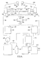
- Apparatus incorporating metering means of the kind illustrated in Figure 3 is shown diagrammatically in Figure 4.
- the apparatus is intended for use in dispensing beer, the beer dispensed being a mixture of strong beer and carbonated water. On each operation of the apparatus, as described below, a standard volume of beer, typically half a pint is dispensed.
- a keg 41 contains strong beer.
- the strong beer may have an alcohol content four or five times higher than that required for consumption.
- the headspace of the keg is supplied with carbon dioxide from a cylinder 42 by way of a pipe 43.
- a pipe 44 leads from the keg 41 to the inlet of a centrifugal pump 45, the outlet of the pump leading to the inlet of a fob detector 46.
- the pump is arranged to operate when ever the apparatus is in a state such as to permit strong beer to be pumped through it.
- the fob detector incorporates a chamber of rather greater capacity than the volume of strong beer metered out during any one operation of the apparatus.
- a liquid level sensor 47 Near the top of the chamber is a liquid level sensor 47 which, when the level of liquid in the chamber is sufficiently high, sends an electrical signal by way of a line 48 to an AND gate 49 connected to a control unit 50. Should the level of liquid in the chamber fall, the sensor 47 fails to detect the presence of liquid and ceases to send a signal to the AND gate 49.
- the sensor 47 may conveniently comprise a reed switch inside a fixed, sealed housing, and a float which contains a permanent magnet and which is pivoted to the housing about a horizontal axis.
- the arrangement is such that if the level of liquid in the chamber falls below a predetermined level the float drops gravitationally to a lowered position such that its magnet cannot operate the reed switch, but that when the chamber is full of liquid the float moves to a raised position in which its magnet causes the reed switch to close.
- valve unit 52 At the bottom of the chamber of the fob detector 46 is an outlet leading to a pipe 51 which in turn leads to the inlet of a valve unit 52.
- An outlet pipe 53 leads from the valve unit to a dispense nozzle 54 disposed in a dispense head (not shown).
- a pair of feed pipes 55 and 56 extend between the valve unit and a metering unit 57 similar to the measuring means illustrated in Figure 3.
- the valve unit is capable of assuming each of two different states. In one state it connects the pipe 51 to the feed pipe 55 and it connects the feed pipe 56 to the outlet pipe 53. In the other state it connects the pipe 51 to the feed pipe 56 and it connects the feed pipe 55 to the outlet pipe 53. Each successive change in state is initiated by an electrical signal from the control unit 50.
- the metering unit 57 is similar in construction to that illustrated in Figure 3, and its component parts have the same reference numerals as those in Figure 3.
- the cylinder, with its closure discs 31 and 32 is adjustable axially relatively to the barrier 26, the disc 27 and the tube 25.
- end portions of the tube 25 are externally screw-threaded and are engaged by nuts (not shown) which abut the outer faces of the closure discs 31 and 32.
- nuts not shown
- one nut is screwed away from its adjacent closure disc and the other nut is screwed against its adjacent disc so at to push towards the first nut the cylinder assembly comprising the closure discs and the cylinder. Seals may be applied to the nuts so that any unauthorised tampering with the adjustment will be revealed.
- the entire metering unit may be enclosed in a sealed enclosure. The total volume swept out by the pistons 35 and 36, when each moves from one end position of its travel to the other, remains constant, and is independent of the position of adjustment of the cylinder assembly.
- the valve unit 52 incorporates a flow detector (not shown) which sends an electrical signal to an OR gate 58 whenever liquid is flowing from the valve unit to the outlet pipe 53.
- the flow detector may comprise a short vertically disposed tube containing a cylindrical weight. Each weight contains a permanent magnet and is of a density only a little greater than that of water. Each weight is of elongated shape and of rather smaller cross-section than that of the tube. When liquid is flowing through the tube it causes the associated weight to rise in the tube; the magnet in the weight then closes a reed switch adjacent to an upper part of the tube. When the flow of liquid ceases the weight drops again and the switch reopens.
- a water inlet pipe 59 is connected to any suitable supply of water such as a mains supply and leads to a carbon filter 60.
- a pipe 61 leads from the filter to a carbonator 62 by way of a displacement pump 63.
- the pump is operative to spray water into a chamber in the carbonator 62.
- Carbon dioxide which may be derived from the cylinder 42 or from a different source, is also supplied to the chamber and becomes dissolved in the water.
- Liquid level sensors (not shown) are mounted near the top and bottom of the chamber and are connected in a control circuit for the pump 63 in such a manner that when the chamber is nearly empty the pump is switched on and then continues to operate until the chamber is nearly full.
- the capacity of the chamber may be about three quarters of a pint (0.426 l).
- An outlet from the bottom of the carbonator 62 is connected by way of a pipe 64 to a fob detector 65 similar to the fob detector 46.
- a liquid level sensor 66 similar to the sensor 47, supplies a signal to the AND gate 49.
- An outlet from the bottom of the fob detector 65 leads by way of a pipe 67 to a valve unit 68 similar to the valve unit 52.
- An outlet pipe 69 leads from the valve unit 68 to a dispense nozzle 70 in the dispense head that also includes the nozzle 54.
- a pair of feed pipes 71 and 72 are connected between the valve unit 68 and the metering unit and operate in an equivalent manner to the feed pipes 55 and 56.
- the valve unit 68 incorporates a flow detector (not shown) which operates in a manner similar to that incorporated in the valve unit 52, sending an electrical signal to the OR gate 58 whenever liquid is flowing from the valve unit to the outlet pipe 69.
- the dispense nozzles 54 and 70 may merely be mounted side-by-side on or in a dispense head so that in use liquids discharged from them are directed into a glass or other vessel placed beneath them and mix in that vessel.
- the dispense head includes a mixing chamber (not shown) into which the strong beer and carbonated water are discharged and where they become at least partially mixed before being discharged through a single outlet into a glass or other vessel disposed beneath the outlet.
- the arrangement is preferably such that all of the liquid has been discharged gravitationally from the mixing chamber by the end of the dispense operation.
- the capacity of the mixing chamber may be less than that of the total volume of liquid dispensed during any one dispense operation.
- the apparatus preferably includes cooling means (not shown). This may conveniently comprise a refrigerating means for cooling water, a tank for containing the cooled water and pump means for circulating the cooled water as described below. Pipes for conveying strong beer and carbonated water to the fob detectors 46 and 65 respectively preferably incorporate cooling coils immersed in the cooled water in the tank. The carbonator 62 is also preferably immersed in the cooled water. It may even be appropriate in some instances to immerse the fob detectors 46 and 65 and the valve units 52 and 68 in the cooled water.
- the fob units or the valve units or both the fob units and the valve units may be of compact form and may incorporate housings made of a plastics material such as polymethylmethacrylate disposed at the ends of the metering unit 57. Moreover, the whole of the metering unit could be immersed in the cooled water; in that case the cylinder 30 would preferably be made of stainless steel. Whatever arrangement is used, however, it is preferably such that the strong beer and the carbonated water reach the metering means at substantially the same temperature. This avoids thermal distortion of the metering means.
- the outlet pipes 53 and 69 are preferably disposed side-by-side in a thermally insulating sleeve which also contains pipework through which a constant flow of cooled water is maintained by the pump means. Furthermore, the mixing chamber, described above, may also be cooled by means of cold water circulating through a cooling jacket.
- the OR gate 58 passes a signal to the control unit 50 which inhibits it from reversing the state of the valve units.
- FIG 5 shows a practical embodiment of the metering means shown diagrammatically in Figures 3 and 4.
- the component parts are given the same reference numerals as those in Figures 3 and 4.
- the position of the cylinder 30, with its closure discs 31 and 32, can be adjusted relative to the tube 25 and drum 27 by means of locating nuts 74 and 75 which engage externally screw-threaded portions of the tube 25.
- bearers 76 and 77 are disposed between the nuts and the adjacent closure discs.
- Each bearer comprises a small ring 78 at one end against which the nut bears, and a large ring 79 at the other end which bears against both the adjacent closure disc and the adjacent end of the cylinder 30.
- Arms 80 extend between the rings 78 and 79.
- metering means illustrated in either of Figures 3 and 5 may be used for metering out other beverages.
Landscapes
- Engineering & Computer Science (AREA)
- Mechanical Engineering (AREA)
- Physics & Mathematics (AREA)
- Fluid Mechanics (AREA)
- General Physics & Mathematics (AREA)
- Devices For Dispensing Beverages (AREA)
- Package Specialized In Special Use (AREA)
Priority Applications (1)
| Application Number | Priority Date | Filing Date | Title |
|---|---|---|---|
| AT89302918T ATE92889T1 (de) | 1988-03-26 | 1989-03-23 | Vorrichtung zur abgabe von bier und anderen getraenken. |
Applications Claiming Priority (4)
| Application Number | Priority Date | Filing Date | Title |
|---|---|---|---|
| GB888807263A GB8807263D0 (en) | 1988-03-26 | 1988-03-26 | Dispensing of beer |
| GB8807263 | 1988-03-26 | ||
| GB888826652A GB8826652D0 (en) | 1988-11-15 | 1988-11-15 | Dispensing of beer |
| GB8826652 | 1988-11-15 |
Publications (2)
| Publication Number | Publication Date |
|---|---|
| EP0335598A1 true EP0335598A1 (fr) | 1989-10-04 |
| EP0335598B1 EP0335598B1 (fr) | 1993-08-11 |
Family
ID=26293696
Family Applications (1)
| Application Number | Title | Priority Date | Filing Date |
|---|---|---|---|
| EP19890302918 Expired - Lifetime EP0335598B1 (fr) | 1988-03-26 | 1989-03-23 | Dispositif pour la distribution de bière et d'autres boissons |
Country Status (3)
| Country | Link |
|---|---|
| EP (1) | EP0335598B1 (fr) |
| DE (1) | DE68908228T2 (fr) |
| ES (1) | ES2044094T3 (fr) |
Cited By (5)
| Publication number | Priority date | Publication date | Assignee | Title |
|---|---|---|---|---|
| EP0479113A1 (fr) * | 1990-10-05 | 1992-04-08 | ALFILL GETRÄNKETECHNIK GmbH | Dispositif pour préparer des boissons |
| DE19613354B4 (de) * | 1996-04-03 | 2004-03-04 | Klaus-Peter Letsch | Zapfanlage |
| EP3178782A1 (fr) * | 2015-12-08 | 2017-06-14 | Carlsberg Breweries A/S | Police spécifique pour système de distribution de boisson, un tel système comprenant une cuve à boisson et procédé de distribution d'un produit de boisson alcoolisée mélangée par le biais dudit système |
| EP3256417A4 (fr) * | 2015-04-15 | 2019-10-16 | Sestra Systems, Inc. | Système de distribution de boisson |
| WO2021162842A1 (fr) | 2020-02-13 | 2021-08-19 | The Coca-Cola Company | Ensemble cartouche de seringue pour système de distribution de boisson |
Citations (5)
| Publication number | Priority date | Publication date | Assignee | Title |
|---|---|---|---|---|
| US2736466A (en) * | 1950-10-11 | 1956-02-28 | Joseph J Rodth | Liquid metering and dispensing device |
| FR1246205A (fr) * | 1958-04-25 | 1960-11-18 | Appareillage pour obtenir un mélange dosé de liquides | |
| DE1757283B1 (de) * | 1968-04-20 | 1971-08-26 | Cornelius Co | Verfahren und Vorrichtung zur Abgabe eines Getraenkes |
| FR2365706A1 (fr) * | 1976-09-24 | 1978-04-21 | Satam Ind | Dispositif melangeur et distributeur d'essence et d'huile |
| WO1987002699A1 (fr) * | 1985-11-04 | 1987-05-07 | Rudolf Pachernegg | Procede pour la production d'une boisson au houblon/malt contenant du gaz carbonique, et dispositif de distribution |
-
1989
- 1989-03-23 DE DE1989608228 patent/DE68908228T2/de not_active Expired - Fee Related
- 1989-03-23 ES ES89302918T patent/ES2044094T3/es not_active Expired - Lifetime
- 1989-03-23 EP EP19890302918 patent/EP0335598B1/fr not_active Expired - Lifetime
Patent Citations (5)
| Publication number | Priority date | Publication date | Assignee | Title |
|---|---|---|---|---|
| US2736466A (en) * | 1950-10-11 | 1956-02-28 | Joseph J Rodth | Liquid metering and dispensing device |
| FR1246205A (fr) * | 1958-04-25 | 1960-11-18 | Appareillage pour obtenir un mélange dosé de liquides | |
| DE1757283B1 (de) * | 1968-04-20 | 1971-08-26 | Cornelius Co | Verfahren und Vorrichtung zur Abgabe eines Getraenkes |
| FR2365706A1 (fr) * | 1976-09-24 | 1978-04-21 | Satam Ind | Dispositif melangeur et distributeur d'essence et d'huile |
| WO1987002699A1 (fr) * | 1985-11-04 | 1987-05-07 | Rudolf Pachernegg | Procede pour la production d'une boisson au houblon/malt contenant du gaz carbonique, et dispositif de distribution |
Cited By (11)
| Publication number | Priority date | Publication date | Assignee | Title |
|---|---|---|---|---|
| EP0479113A1 (fr) * | 1990-10-05 | 1992-04-08 | ALFILL GETRÄNKETECHNIK GmbH | Dispositif pour préparer des boissons |
| DE19613354B4 (de) * | 1996-04-03 | 2004-03-04 | Klaus-Peter Letsch | Zapfanlage |
| EP3256417A4 (fr) * | 2015-04-15 | 2019-10-16 | Sestra Systems, Inc. | Système de distribution de boisson |
| EP3178782A1 (fr) * | 2015-12-08 | 2017-06-14 | Carlsberg Breweries A/S | Police spécifique pour système de distribution de boisson, un tel système comprenant une cuve à boisson et procédé de distribution d'un produit de boisson alcoolisée mélangée par le biais dudit système |
| WO2017097820A1 (fr) * | 2015-12-08 | 2017-06-15 | Carlsberg Breweries A/S | Réservoir de boisson pour système de distribution de boisson, système de distribution de boisson comprenant un réservoir de boisson, et procédé de distribution de produit de boisson alcoolisé mélangé en fournissant un système de distribution de boisson |
| EA035339B1 (ru) * | 2015-12-08 | 2020-05-29 | Карлсберг Брюириз А/С | Источник напитка для системы дозированного розлива напитка, система дозированного розлива напитка, содержащая источник напитка, и способ дозированного розлива смешанного алкогольного питьевого продукта путем обеспечения системы дозированного розлива напитка |
| WO2021162842A1 (fr) | 2020-02-13 | 2021-08-19 | The Coca-Cola Company | Ensemble cartouche de seringue pour système de distribution de boisson |
| CN115003619A (zh) * | 2020-02-13 | 2022-09-02 | 可口可乐公司 | 用于饮料分配系统的注射筒组件 |
| EP4103508A4 (fr) * | 2020-02-13 | 2024-03-13 | The Coca-Cola Company | Ensemble cartouche de seringue pour système de distribution de boisson |
| US12116256B2 (en) | 2020-02-13 | 2024-10-15 | The Coca-Cola Company | Syringe cartridge assembly for a beverage dispensing system |
| CN115003619B (zh) * | 2020-02-13 | 2025-09-30 | 可口可乐公司 | 用于饮料分配系统的注射筒组件 |
Also Published As
| Publication number | Publication date |
|---|---|
| DE68908228T2 (de) | 1993-11-25 |
| DE68908228D1 (de) | 1993-09-16 |
| ES2044094T3 (es) | 1994-01-01 |
| EP0335598B1 (fr) | 1993-08-11 |
Similar Documents
| Publication | Publication Date | Title |
|---|---|---|
| US5725125A (en) | Method of and means for providing multiple flavored beverages from a dispensing valve from a beverage dispensing unit | |
| RU2070398C1 (ru) | Сатуратор для приготовления газированной воды в контейнере без образования в нем газообразной фазы | |
| CN1251938C (zh) | 饮料分配系统及从饮料分配器提供饮料选择的方法 | |
| KR100494971B1 (ko) | 유체 이송 시스템, 및 유체 공급 탱크로부터 유체 유출 라인으로 유체를 이송하는 방법 | |
| US4764315A (en) | Water cooler and carbonator | |
| US3780198A (en) | System for carbonating beverages | |
| US5011700A (en) | Syrup delivery system for carbonated beverages | |
| US5021250A (en) | Apparatus and method for dispensing purified and carbonated liquids | |
| US3552726A (en) | Motorless carbonator and method of operation | |
| CA2113481A1 (fr) | Systeme de controle du volume de liquides administres | |
| KR20010013924A (ko) | 산소화 음료수 냉각기 | |
| CA1317913C (fr) | Systeme de distribution de boissons au moyen d'un dispositif de dosage volumetrique | |
| US20060288874A1 (en) | In-Line, Instantaneous Carbonation System | |
| CN112209324B (zh) | 多功能填充阀 | |
| EP0335598A1 (fr) | Dispositif pour la distribution de bière et d'autres boissons | |
| US5293909A (en) | Method and apparatus for mixing beverage components | |
| GB2247848A (en) | Apparatus for dispensing drinks | |
| US2455681A (en) | Method of preparing carbonated beverages | |
| EP1088784B1 (fr) | Appareil pour la fabrication et la distribution de boissons avec glace concassée | |
| GB2216871A (en) | The dispensing of beer and other beverages | |
| US6293430B1 (en) | Apparatus and method for recovering beverage syrup | |
| US5141011A (en) | Liquid proportioner apparatus and method | |
| GB2261442A (en) | Process for freeze-concentrating beer | |
| CA1231667A (fr) | Traitement du lait | |
| US20240279042A1 (en) | Device for filling containers and method for monitoring the filling process |
Legal Events
| Date | Code | Title | Description |
|---|---|---|---|
| PUAI | Public reference made under article 153(3) epc to a published international application that has entered the european phase |
Free format text: ORIGINAL CODE: 0009012 |
|
| AK | Designated contracting states |
Kind code of ref document: A1 Designated state(s): AT BE CH DE ES FR GR IT LI LU NL SE |
|
| 17P | Request for examination filed |
Effective date: 19900308 |
|
| 17Q | First examination report despatched |
Effective date: 19910826 |
|
| GRAA | (expected) grant |
Free format text: ORIGINAL CODE: 0009210 |
|
| AK | Designated contracting states |
Kind code of ref document: B1 Designated state(s): AT BE CH DE ES FR GR IT LI LU NL SE |
|
| PG25 | Lapsed in a contracting state [announced via postgrant information from national office to epo] |
Ref country code: LI Effective date: 19930811 Ref country code: GR Free format text: LAPSE BECAUSE OF FAILURE TO SUBMIT A TRANSLATION OF THE DESCRIPTION OR TO PAY THE FEE WITHIN THE PRESCRIBED TIME-LIMIT Effective date: 19930811 Ref country code: CH Effective date: 19930811 |
|
| REF | Corresponds to: |
Ref document number: 92889 Country of ref document: AT Date of ref document: 19930815 Kind code of ref document: T |
|
| REF | Corresponds to: |
Ref document number: 68908228 Country of ref document: DE Date of ref document: 19930916 |
|
| ITF | It: translation for a ep patent filed | ||
| ET | Fr: translation filed | ||
| REG | Reference to a national code |
Ref country code: CH Ref legal event code: PL |
|
| REG | Reference to a national code |
Ref country code: GR Ref legal event code: FG4A Free format text: 3009178 |
|
| REG | Reference to a national code |
Ref country code: ES Ref legal event code: FG2A Ref document number: 2044094 Country of ref document: ES Kind code of ref document: T3 |
|
| PG25 | Lapsed in a contracting state [announced via postgrant information from national office to epo] |
Ref country code: AT Effective date: 19940323 |
|
| PG25 | Lapsed in a contracting state [announced via postgrant information from national office to epo] |
Ref country code: SE Free format text: LAPSE BECAUSE OF NON-PAYMENT OF DUE FEES Effective date: 19940324 Ref country code: ES Free format text: LAPSE BECAUSE OF NON-PAYMENT OF DUE FEES Effective date: 19940324 |
|
| PG25 | Lapsed in a contracting state [announced via postgrant information from national office to epo] |
Ref country code: LU Free format text: LAPSE BECAUSE OF NON-PAYMENT OF DUE FEES Effective date: 19940331 Ref country code: BE Effective date: 19940331 |
|
| PLBE | No opposition filed within time limit |
Free format text: ORIGINAL CODE: 0009261 |
|
| STAA | Information on the status of an ep patent application or granted ep patent |
Free format text: STATUS: NO OPPOSITION FILED WITHIN TIME LIMIT |
|
| 26N | No opposition filed | ||
| BERE | Be: lapsed |
Owner name: BASS P.L.C. Effective date: 19940331 |
|
| PG25 | Lapsed in a contracting state [announced via postgrant information from national office to epo] |
Ref country code: NL Effective date: 19941001 |
|
| NLV4 | Nl: lapsed or anulled due to non-payment of the annual fee | ||
| PG25 | Lapsed in a contracting state [announced via postgrant information from national office to epo] |
Ref country code: FR Effective date: 19941130 |
|
| PG25 | Lapsed in a contracting state [announced via postgrant information from national office to epo] |
Ref country code: DE Effective date: 19941201 |
|
| REG | Reference to a national code |
Ref country code: FR Ref legal event code: ST |
|
| EUG | Se: european patent has lapsed |
Ref document number: 89302918.1 Effective date: 19941010 |
|
| REG | Reference to a national code |
Ref country code: GR Ref legal event code: MM2A Free format text: 3009178 |
|
| REG | Reference to a national code |
Ref country code: ES Ref legal event code: FD2A Effective date: 19990503 |
|
| PG25 | Lapsed in a contracting state [announced via postgrant information from national office to epo] |
Ref country code: IT Free format text: LAPSE BECAUSE OF NON-PAYMENT OF DUE FEES Effective date: 20050323 |