EP0335621A1 - Abschliesselement für isolierte Hohlwände - Google Patents
Abschliesselement für isolierte Hohlwände Download PDFInfo
- Publication number
- EP0335621A1 EP0335621A1 EP89302977A EP89302977A EP0335621A1 EP 0335621 A1 EP0335621 A1 EP 0335621A1 EP 89302977 A EP89302977 A EP 89302977A EP 89302977 A EP89302977 A EP 89302977A EP 0335621 A1 EP0335621 A1 EP 0335621A1
- Authority
- EP
- European Patent Office
- Prior art keywords
- profile
- cavity
- wall
- limb
- adjacent
- Prior art date
- Legal status (The legal status is an assumption and is not a legal conclusion. Google has not performed a legal analysis and makes no representation as to the accuracy of the status listed.)
- Granted
Links
- 238000007789 sealing Methods 0.000 title claims abstract description 53
- XLYOFNOQVPJJNP-UHFFFAOYSA-N water Substances O XLYOFNOQVPJJNP-UHFFFAOYSA-N 0.000 claims abstract description 17
- 230000006835 compression Effects 0.000 claims abstract description 4
- 238000007906 compression Methods 0.000 claims abstract description 4
- 230000005494 condensation Effects 0.000 claims abstract 3
- 238000009833 condensation Methods 0.000 claims abstract 3
- 239000000463 material Substances 0.000 claims description 13
- 239000006260 foam Substances 0.000 claims description 7
- 238000000034 method Methods 0.000 claims description 5
- 229920003020 cross-linked polyethylene Polymers 0.000 claims description 2
- 239000004703 cross-linked polyethylene Substances 0.000 claims description 2
- 229920000092 linear low density polyethylene Polymers 0.000 claims description 2
- 239000004707 linear low-density polyethylene Substances 0.000 claims description 2
- 229920005989 resin Polymers 0.000 claims description 2
- 239000011347 resin Substances 0.000 claims description 2
- 238000010276 construction Methods 0.000 abstract description 11
- 238000009413 insulation Methods 0.000 description 19
- 239000011449 brick Substances 0.000 description 5
- -1 polyethylene Polymers 0.000 description 3
- 239000004575 stone Substances 0.000 description 3
- 239000004698 Polyethylene Substances 0.000 description 2
- 230000004888 barrier function Effects 0.000 description 2
- 239000012774 insulation material Substances 0.000 description 2
- 238000012986 modification Methods 0.000 description 2
- 230000004048 modification Effects 0.000 description 2
- 229920000573 polyethylene Polymers 0.000 description 2
- 239000004743 Polypropylene Substances 0.000 description 1
- 239000004793 Polystyrene Substances 0.000 description 1
- 238000009435 building construction Methods 0.000 description 1
- DQXBYHZEEUGOBF-UHFFFAOYSA-N but-3-enoic acid;ethene Chemical compound C=C.OC(=O)CC=C DQXBYHZEEUGOBF-UHFFFAOYSA-N 0.000 description 1
- 239000004568 cement Substances 0.000 description 1
- 230000000295 complement effect Effects 0.000 description 1
- 238000005336 cracking Methods 0.000 description 1
- 239000005038 ethylene vinyl acetate Substances 0.000 description 1
- 239000006261 foam material Substances 0.000 description 1
- 230000007062 hydrolysis Effects 0.000 description 1
- 238000006460 hydrolysis reaction Methods 0.000 description 1
- 230000008595 infiltration Effects 0.000 description 1
- 238000001764 infiltration Methods 0.000 description 1
- 238000009434 installation Methods 0.000 description 1
- 239000000203 mixture Substances 0.000 description 1
- 229920001200 poly(ethylene-vinyl acetate) Polymers 0.000 description 1
- 229920000098 polyolefin Polymers 0.000 description 1
- 229920001155 polypropylene Polymers 0.000 description 1
- 229920002223 polystyrene Polymers 0.000 description 1
- 229920002635 polyurethane Polymers 0.000 description 1
- 239000004814 polyurethane Substances 0.000 description 1
- 229920000915 polyvinyl chloride Polymers 0.000 description 1
- 239000004800 polyvinyl chloride Substances 0.000 description 1
- 125000006850 spacer group Chemical group 0.000 description 1
- 238000013022 venting Methods 0.000 description 1
Images

Classifications
-
- E—FIXED CONSTRUCTIONS
- E04—BUILDING
- E04B—GENERAL BUILDING CONSTRUCTIONS; WALLS, e.g. PARTITIONS; ROOFS; FLOORS; CEILINGS; INSULATION OR OTHER PROTECTION OF BUILDINGS
- E04B1/00—Constructions in general; Structures which are not restricted either to walls, e.g. partitions, or floors or ceilings or roofs
- E04B1/62—Insulation or other protection; Elements or use of specified material therefor
- E04B1/74—Heat, sound or noise insulation, absorption, or reflection; Other building methods affording favourable thermal or acoustical conditions, e.g. accumulating of heat within walls
- E04B1/76—Heat, sound or noise insulation, absorption, or reflection; Other building methods affording favourable thermal or acoustical conditions, e.g. accumulating of heat within walls specifically with respect to heat only
Definitions
- This invention relates to an elongate air sealing member made from a flexible, compressible, water repellant material having, inter alia , thermal insulating properties. More particularly, this invention relates to an auxiliary insulating profile for installation in a cavity wall.
- insulated, cavity wall construction In certain types of building construction, known as insulated, cavity wall construction, it is customary to have a construction comprising an outer wall, an air gap or cavity that is eventually vented, and an inner wall. Such a construction usually includes insulation boards or insulation materials applied to the inside cavity wall in such a manner that a venting space remains between the insulating boards and the outer wall. It has been shown that natural convection, meaning thermal air circulation, causes substantial heat losses around insulation layers and/or insulation boards, as compared to calculated theoretical values.
- the inner wall is normally not smooth at its cavity side, i.e. there are projecting cement residues and brick dimensional tolerances which prevent insulating boards from coming to rest perfectly against the inner-wall. Furthermore, the top and bottom edges of insulation layers are normally not sealed in an airtight manner with other building parts. Therefore, it is clear that in order to obtain proper thermal insulation, it is necessary to take extra precautions and work very accurately, which is time-consuming and hence an expensive way of building an insulated, cavity wall construction.
- the auxiliary member comprises essentially an L-shaped cross section of a flexible, compressible, water repellant material having thermal insulation properties. Such a profile is adapted to fit against the butt edge of an insulating board.
- Other types of L-shaped profiles can be employed to accommodate insulating boards having tongue-and-groove edges, or ship-lapped edges.
- L-shaped profiles containing various other minor modifications can also be employed to accommodate the edges of specially formed insulating boards, and these are contemplated as falling within the scope of the present invention.
- any flexible, compressible, water repellant material having thermal insulating properties can be employed in the practice of this invention.
- Such materials include, for example, synthetic foams made from polyethylene, polypropylene, polyurethane, ethylene vinyl acetate, polyvinyl chloride, polystyrene and the like, both extruded and expanded.
- synthetic foams made from polyethylene, polypropylene, polyurethane, ethylene vinyl acetate, polyvinyl chloride, polystyrene and the like, both extruded and expanded.
- elastic, closed-cell, crosslinked and non-crosslinked polyolefin foams are employed.
- cavity sealing profiles comprising closed-cell, non-crosslinked polyethylene foam or mixtures containing such foams are utilized in the present invention.
- These materials have very good thermal insulating properties, are not susceptible to hydrolysis and absorb practically no water.
- polyethylene foam materials are resilient and can absorb the tensile and compressive stresses arising from temperature fluctuations or load pressures. Due to their resilience they are able to deform under stress and pressure and thereby fit tightly into a cavity wall without cracking.
- cavity sealing profiles made from such materials form a tight compression fit within the cavity that effectively prevents any heat losses from occurring via thermal convection.
- the desired profiles can be milled to shape from block foam, molded to shape, or extruded to shape through special dies.
- the cavity sealing profile is adapted to be placed in the cavity of the wall in such a manner that the outer longitudinal face of the vertical member of the L-shaped profile is adjacent to the inner surface of the exterior wall, while the longitudinal edge of the horizontal limb of the L-shaped cavity sealing profile is adjacent to the inner cavity surface of the interior wall.
- auxiliary profile is in the construction of the cavity wall itself. In some countries, both inner and outer cavity walls are progressively constructed at the same time. By seating the auxiliary profile at the base of the cavity of the cavity wall, it forms a spacer between the inner and outer walls, thereby providing and maintaining a proper cavity width. At the same time, the auxiliary profile helps to prevent cold bridges from occurring at connections between insulation surfaces and other construction parts. Furthermore, as a construction aid, once the longitudinal surface of the horizontal limb of the cavity sealing profile is plumb and level, insulation boards subsequently added thereto will also automatically be level.
- a second cavity sealing profile is attached which is in opposition to the base cavity sealing profile, thereby effectively sealing all air leaks both at the bottom and at the top of the cavity.
- additional cavity sealing profiles can be installed at vertical corners and around wall openings, such as doors and windows.
- the cavity sealing profiles of the present invention can serve to discharge any condensate or rain water that may occur in the cavity between the insulating layer and the inner surface of the exterior wall.
- the top surface of the cavity sealing profile is sloped downwardly to the exterior wall.
- the inclined top surface conducts any water or condensate towards the direction of the external wall. The water and condensate can be easily discharged via openings provided near the lowest point of the inclined top surface leading to the exterior of the outer wall.
- a moisture-proof, tear resistant, flexible film can be employed which serves as a condensate or water barrier.
- a film is made to adhere to the sloping surface of the cavity sealing profile.
- the top edge of this film is secured to the exterior surface of the insulation board, whereas the bottom edge of this film leads to the outside of the exterior wall via a horizontal joint in the outer wall.
- Such a film effectively serves as a water impermeable barrier and conduit to the exterior surface of the outer wall for any rainwater or condensate that finds its way inside the cavity wall.
- the top of this film can be conveniently secured to the exterior surface of the insulation boards by passing the film through a horizontal joint of the insulation layer in such a manner as not to disturb the air tightness of the joint.
- Any type of moisture proof film can be utilized in connection with this invention. Due to the hard usage to which such a film is subjected during construction, it is desirable to employ a film of sufficient thickness so as to be tear and puncture resistant, but which still retains its flexibility. Cast or blown films made from linear low density polyethylene resins are particularly useful in the practice of this invention. They exhibit exceptional tear, toughness and puncture resistant properties and are completely water resistant. The film can be so attached to the auxiliary profile that it allows a horizontal overlap which can be either a loose-laid overlap or which can be sealed together at the job site.
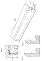
- FIG. 1 One embodiment of an elongate cavity sealing profile (1) is shown in Figure 1, which has a substantially L-shaped cross section, and which is made from a flexible, compressible material having thermal insulating properties.
- the free end of the vertical limb (2) of the L-shaped cavity sealing profile (1) has a top surface (3) extending obliquely downwards from its inner longitudinal face (4) to the direction of its outer longitudinal face (5).
- a moisture-resistant, film material (6) may be fixed to the top sloping surface (3), said film being of sufficient length so as to substantially extend beyond the top and bottom edges of the sloping surface (3).
- the cavity sealing profile (1) is adapted to be a compression fit in the base of the cavity (7) of a cavity wall (9,10).
- the bottom longitudinal face (11) of said profile rests on the foundation (8) or the base of the cavity (7), while the outer longitudinal face (5) is adjacent to the inner surface of the exterior wall (10).
- the longitudinal edge (13) of the horizontal limb (12) rests adjacent to the inner surface of the interior wall (9).
- a part of an insulating board (14) is adapted to be confined therein. It is clear that the sealing member (1) should be of such a length as to seal the entire length of the cavity wall.
- the inclined top surface (3) of the cavity sealing profile (1) is designed so as to collect any rain water or moisture condensate present in the cavity (7), and discharge it to the outside of the exterior wall (10).
- the sealing profile (1) is positioned in such a manner that the lowest point of the top surface (3) is flush with a horizontal joint (15) formed by two rows of bricks in the exterior wall (10).
- the moisture-proof, tear resistant, flexible film (6) is affixed to the top surface (3) of the cavity sealing profile (1).
- the top edge of this film can be readily held in place by passing it through a joint (20) formed between two insulation boards (14), care being taken not to disturb the air tightness of the joint.
- the lower edge of the film can be sloped downward and led to the exterior via the horizontal joint (15).
- the top of the cavity wall can be enclosed by reversing the cavity sealing profile so that the longitudinal face (11) of said profile (1) is adjacent to the ceiling (16).
- Figures 3 and 4 show a vertical and horizontal cross-section of a cavity wall adjacent to a window or door opening, and shows how the cavity sealing profile (1) can be mounted in such a case.
- Figure 3 shows the use of a course of brick or stone laid on edge (17), and the placement of the sealing profile (1) at the appropriate height against the inner face of said course of brick or stone.
- edge (17) is a lintel or ornamental supporting structure of natural stone, having a larger vertical dimension than the outer longitudinal face (5) of the cavity sealing profile.
- the joints (15) between the lintel and superposed brick function as an outlet channel for any moisture or water the cavity may receive.
- the cavity formed between the frame (18) and the bottom longitudinal face (11) of the sealing member (1) can be filled with an insulation member (14) and then with an expandable foam or soft insulation material (19).
- an insulation member (14) and then with an expandable foam or soft insulation material (19).
- the cavity sealing profile can be placed against the frame (18) without objection, since its positioning near a joint is not necessary in the vertical plane.
- Figure 5 shows an embodiment of how a cavity sealing profile (1) can function as a cavity sealer in the situation where the external walls are set at right angles to each other. Such a positioning of the sealing profile results in effectively sealing any gaps created by improperly fitting insulating boards. Since even small gaps of one or two millimeters can create thermal convection with resulting heat loss, the use of a cavity sealing profile to seal a corner joint is a further advantage of the present invention.
- Figures 6 and 7 show two cross sectional variations of the sealing profile (1).
- the ridged horizontal limb ensures that the edges of the insulation board (14) having a complementary profile, fit snugly and remain air tight.
- the fact that the cavity sealing profile can be slightly deformed when the edge of the insulation board is pressed against the L-shaped surface of the cavity sealing profile ensures a tight fit. The result is that excellent sealing is obtained and no undesirable air circulation or thermal convection occurs between the inner surface of the interior wall and the insulation boards.
- the sealing member can be used between any two spaced-apart walls to prevent undesirable air circulation or convection from occurring.
Landscapes
- Physics & Mathematics (AREA)
- Engineering & Computer Science (AREA)
- Architecture (AREA)
- Acoustics & Sound (AREA)
- Electromagnetism (AREA)
- Civil Engineering (AREA)
- Structural Engineering (AREA)
- Building Environments (AREA)
Applications Claiming Priority (2)
| Application Number | Priority Date | Filing Date | Title |
|---|---|---|---|
| NL8800789 | 1988-03-29 | ||
| NL8800789A NL8800789A (nl) | 1988-03-29 | 1988-03-29 | Hulpelement voor een geisoleerde spouwmuur. |
Publications (2)
| Publication Number | Publication Date |
|---|---|
| EP0335621A1 true EP0335621A1 (de) | 1989-10-04 |
| EP0335621B1 EP0335621B1 (de) | 1993-06-02 |
Family
ID=19852024
Family Applications (1)
| Application Number | Title | Priority Date | Filing Date |
|---|---|---|---|
| EP19890302977 Expired - Lifetime EP0335621B1 (de) | 1988-03-29 | 1989-03-23 | Abschliesselement für isolierte Hohlwände |
Country Status (5)
| Country | Link |
|---|---|
| EP (1) | EP0335621B1 (de) |
| CA (1) | CA1312441C (de) |
| DE (1) | DE68906817D1 (de) |
| DK (1) | DK167700B1 (de) |
| NL (1) | NL8800789A (de) |
Families Citing this family (2)
| Publication number | Priority date | Publication date | Assignee | Title |
|---|---|---|---|---|
| US9598891B2 (en) | 2015-03-23 | 2017-03-21 | Jk Worldwide Enterprises Inc. | Thermal break for use in construction |
| US9863137B2 (en) | 2015-03-23 | 2018-01-09 | Jk Worldwide Enterprises Inc. | Thermal break for use in construction |
Citations (4)
| Publication number | Priority date | Publication date | Assignee | Title |
|---|---|---|---|---|
| US3881292A (en) * | 1973-03-26 | 1975-05-06 | W H Porter Inc | Insulating structural assembly and stud member for forming same |
| GB1517966A (en) * | 1976-12-24 | 1978-07-19 | Stressline Ltd | Lintels |
| AT344380B (de) * | 1975-08-19 | 1978-07-25 | Winkler Hans H Dipl Ing Dkfm | Zweischaliges, hinterlueftetes mauerwerk |
| GB2171430A (en) * | 1983-01-31 | 1986-08-28 | Philip Stephen Doyle | A lintel |
-
1988
- 1988-03-29 NL NL8800789A patent/NL8800789A/nl not_active Application Discontinuation
-
1989
- 1989-03-22 DK DK141889A patent/DK167700B1/da not_active IP Right Cessation
- 1989-03-23 CA CA000594754A patent/CA1312441C/en not_active Expired - Fee Related
- 1989-03-23 DE DE8989302977T patent/DE68906817D1/de not_active Expired - Lifetime
- 1989-03-23 EP EP19890302977 patent/EP0335621B1/de not_active Expired - Lifetime
Patent Citations (4)
| Publication number | Priority date | Publication date | Assignee | Title |
|---|---|---|---|---|
| US3881292A (en) * | 1973-03-26 | 1975-05-06 | W H Porter Inc | Insulating structural assembly and stud member for forming same |
| AT344380B (de) * | 1975-08-19 | 1978-07-25 | Winkler Hans H Dipl Ing Dkfm | Zweischaliges, hinterlueftetes mauerwerk |
| GB1517966A (en) * | 1976-12-24 | 1978-07-19 | Stressline Ltd | Lintels |
| GB2171430A (en) * | 1983-01-31 | 1986-08-28 | Philip Stephen Doyle | A lintel |
Also Published As
| Publication number | Publication date |
|---|---|
| CA1312441C (en) | 1993-01-12 |
| EP0335621B1 (de) | 1993-06-02 |
| DE68906817D1 (de) | 1993-07-08 |
| NL8800789A (nl) | 1989-10-16 |
| DK167700B1 (da) | 1993-12-06 |
| DK141889A (da) | 1989-09-30 |
| DK141889D0 (da) | 1989-03-22 |
Similar Documents
| Publication | Publication Date | Title |
|---|---|---|
| US20240263511A1 (en) | Window sill flashing | |
| EP3625402B1 (de) | Dynamisches feuerbeständiges wärmedämm- und abdichtungssystem zur verwendung mit vorhangfassadenstrukturen | |
| US5960604A (en) | Interlocking masonry unit and wall | |
| US5092092A (en) | Auxiliary member for insulated cavity walls | |
| US4277926A (en) | Vented insulation system for existing structure | |
| EP0250989A1 (de) | Vorhangfassade aus Glas und Befestigung mit Dichtung und Metallelementen | |
| EP0335621B1 (de) | Abschliesselement für isolierte Hohlwände | |
| GB2148970A (en) | A metal-frame curtain-wall structure with sound and heat ruptures | |
| US8011145B1 (en) | Segmented joint for masonry construction | |
| GB2238329A (en) | Building panel | |
| GB2024911A (en) | Buildings | |
| US3834097A (en) | Double glazed window assembly | |
| KR200377961Y1 (ko) | 보강부재를 구비한 건축용 복합 판넬 | |
| CA2295452A1 (en) | Bulkhead door seal | |
| CN111434870A (zh) | 包括瞬时变形区域的隔离框架 | |
| JPH0657830A (ja) | 押し出し成形セメント板の接合部止水構造 | |
| JP2562227B2 (ja) | 外壁の防水構造 | |
| CN100390360C (zh) | 气环式补空外墙结构 | |
| EP1258573B1 (de) | Blockförmiges Bauelement | |
| KR0172036B1 (ko) | 커튼월용 기밀차단막의 구조 | |
| JP7391636B2 (ja) | ガスケットとガスケット付き外壁パネル | |
| WO2024260641A1 (en) | Apparatus and method for installing a closure in a building | |
| JP2025070035A (ja) | 窓開口部を含む外断熱外壁構造 | |
| JP4931463B2 (ja) | 型枠兼用外断熱パネル | |
| GB2297991A (en) | Frame assembly |
Legal Events
| Date | Code | Title | Description |
|---|---|---|---|
| PUAI | Public reference made under article 153(3) epc to a published international application that has entered the european phase |
Free format text: ORIGINAL CODE: 0009012 |
|
| AK | Designated contracting states |
Kind code of ref document: A1 Designated state(s): BE DE ES FR GB GR IT LU NL |
|
| 17P | Request for examination filed |
Effective date: 19890926 |
|
| 17Q | First examination report despatched |
Effective date: 19900706 |
|
| GRAA | (expected) grant |
Free format text: ORIGINAL CODE: 0009210 |
|
| AK | Designated contracting states |
Kind code of ref document: B1 Designated state(s): BE DE ES FR GB GR IT LU NL |
|
| PG25 | Lapsed in a contracting state [announced via postgrant information from national office to epo] |
Ref country code: IT Free format text: LAPSE BECAUSE OF FAILURE TO SUBMIT A TRANSLATION OF THE DESCRIPTION OR TO PAY THE FEE WITHIN THE PRESCRIBED TIME-LIMIT;WARNING: LAPSES OF ITALIAN PATENTS WITH EFFECTIVE DATE BEFORE 2007 MAY HAVE OCCURRED AT ANY TIME BEFORE 2007. THE CORRECT EFFECTIVE DATE MAY BE DIFFERENT FROM THE ONE RECORDED. Effective date: 19930602 Ref country code: GR Free format text: LAPSE BECAUSE OF FAILURE TO SUBMIT A TRANSLATION OF THE DESCRIPTION OR TO PAY THE FEE WITHIN THE PRESCRIBED TIME-LIMIT Effective date: 19930602 Ref country code: ES Free format text: THE PATENT HAS BEEN ANNULLED BY A DECISION OF A NATIONAL AUTHORITY Effective date: 19930602 Ref country code: FR Effective date: 19930602 Ref country code: NL Effective date: 19930602 Ref country code: DE Effective date: 19930602 |
|
| REF | Corresponds to: |
Ref document number: 68906817 Country of ref document: DE Date of ref document: 19930708 |
|
| EN | Fr: translation not filed | ||
| NLV1 | Nl: lapsed or annulled due to failure to fulfill the requirements of art. 29p and 29m of the patents act | ||
| PG25 | Lapsed in a contracting state [announced via postgrant information from national office to epo] |
Ref country code: LU Free format text: LAPSE BECAUSE OF NON-PAYMENT OF DUE FEES Effective date: 19940331 |
|
| PLBE | No opposition filed within time limit |
Free format text: ORIGINAL CODE: 0009261 |
|
| STAA | Information on the status of an ep patent application or granted ep patent |
Free format text: STATUS: NO OPPOSITION FILED WITHIN TIME LIMIT |
|
| 26N | No opposition filed | ||
| PGFP | Annual fee paid to national office [announced via postgrant information from national office to epo] |
Ref country code: GB Payment date: 20001223 Year of fee payment: 13 |
|
| PGFP | Annual fee paid to national office [announced via postgrant information from national office to epo] |
Ref country code: BE Payment date: 20010315 Year of fee payment: 13 |
|
| REG | Reference to a national code |
Ref country code: GB Ref legal event code: IF02 |
|
| PG25 | Lapsed in a contracting state [announced via postgrant information from national office to epo] |
Ref country code: GB Free format text: LAPSE BECAUSE OF NON-PAYMENT OF DUE FEES Effective date: 20020323 |
|
| PG25 | Lapsed in a contracting state [announced via postgrant information from national office to epo] |
Ref country code: BE Free format text: LAPSE BECAUSE OF NON-PAYMENT OF DUE FEES Effective date: 20020331 |
|
| BERE | Be: lapsed |
Owner name: THE *DOW CHEMICAL CY Effective date: 20020331 |
|
| GBPC | Gb: european patent ceased through non-payment of renewal fee |
Effective date: 20020323 |