EP0335652B1 - Dispositifs destinés à l'usage des patients ostomiques - Google Patents
Dispositifs destinés à l'usage des patients ostomiques Download PDFInfo
- Publication number
- EP0335652B1 EP0335652B1 EP89303036A EP89303036A EP0335652B1 EP 0335652 B1 EP0335652 B1 EP 0335652B1 EP 89303036 A EP89303036 A EP 89303036A EP 89303036 A EP89303036 A EP 89303036A EP 0335652 B1 EP0335652 B1 EP 0335652B1
- Authority
- EP
- European Patent Office
- Prior art keywords
- chute
- frame
- feature
- tape
- patient
- Prior art date
- Legal status (The legal status is an assumption and is not a legal conclusion. Google has not performed a legal analysis and makes no representation as to the accuracy of the status listed.)
- Expired - Lifetime
Links
Images



Classifications
-
- A—HUMAN NECESSITIES
- A61—MEDICAL OR VETERINARY SCIENCE; HYGIENE
- A61F—FILTERS IMPLANTABLE INTO BLOOD VESSELS; PROSTHESES; DEVICES PROVIDING PATENCY TO, OR PREVENTING COLLAPSING OF, TUBULAR STRUCTURES OF THE BODY, e.g. STENTS; ORTHOPAEDIC, NURSING OR CONTRACEPTIVE DEVICES; FOMENTATION; TREATMENT OR PROTECTION OF EYES OR EARS; BANDAGES, DRESSINGS OR ABSORBENT PADS; FIRST-AID KITS
- A61F5/00—Orthopaedic methods or devices for non-surgical treatment of bones or joints; Nursing devices ; Anti-rape devices
- A61F5/44—Devices worn by the patient for reception of urine, faeces, catamenial or other discharge; Colostomy devices
- A61F5/445—Colostomy, ileostomy or urethrostomy devices
-
- A—HUMAN NECESSITIES
- A61—MEDICAL OR VETERINARY SCIENCE; HYGIENE
- A61F—FILTERS IMPLANTABLE INTO BLOOD VESSELS; PROSTHESES; DEVICES PROVIDING PATENCY TO, OR PREVENTING COLLAPSING OF, TUBULAR STRUCTURES OF THE BODY, e.g. STENTS; ORTHOPAEDIC, NURSING OR CONTRACEPTIVE DEVICES; FOMENTATION; TREATMENT OR PROTECTION OF EYES OR EARS; BANDAGES, DRESSINGS OR ABSORBENT PADS; FIRST-AID KITS
- A61F5/00—Orthopaedic methods or devices for non-surgical treatment of bones or joints; Nursing devices ; Anti-rape devices
- A61F5/44—Devices worn by the patient for reception of urine, faeces, catamenial or other discharge; Colostomy devices
- A61F5/442—Devices worn by the patient for reception of urine, faeces, catamenial or other discharge; Colostomy devices having irrigation ports or means
Definitions
- This invention relates to devices for use by ostomy patients, in particular patients who have undergone ileosostomy or urostomy surgery.
- a device for use by ostomy patients which device comprises a frame adapted for the lap of a seated patient, a chute depending from the frame and intended, in use, to extend between the legs or thighs of the patient, an opening in said frame and communicating with the chute whereby the contents of an ostomy pouch can be deposited in and flow down the chute, of respective first and second portions of material, the one connecting the chute detachably to the frame, the other depending from the first portion and constituting or forming part of the chute; and with means, attaching to or forming part of said portions and manipulable therewith by the patient in use to collapse the portions into a disposal bag; both the said portions being constituted by a single and relatively flexible sheet of material in which corner-apertures fit detachably over respective posts on the frame; characterized by the provision of a flexible tape which is connected at one end to the lower end of the chute and has its other end accessible from the level of the frame.
- the flexible tape is preferably arranged so that it extends inside
- the first portion may be basin-shaped and made from relatively rigid material whilst the second portion takes the form of a flexible sleeve having open upper and lower ends; or the frame itself may comprise a flat and relatively rigid sheet with the chute portions fitting in an opening in that sheet.
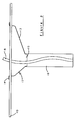
- the device shown in Figures 1 and 2 includes a flat sheet 10 which is formed from a synthetic plastics material and which has sufficient rigidity and strength to enable it to function as a support tray.
- the sheet 10 is of generally rectangular form as shown, with rounded corners, and with an arcuate rebate 11 formed in one of the longer edges of the sheet.
- the support tray provided by the sheet 10 is intended to be placed on the lap of an ostomy patient when seated on the toilet and the purpose of the rebate 11 is accordingly to enable the support tray to fit closely against the trunk of the patient with the patient's stomach fitting within the rebate 11.
- the plastics sheet 10 is formed with a through aperture into which a disposable drainage module 12 is fitted.
- the disposable drainage module includes a first part 13 which is in the form of a plastics moulding; the plastics moulding is relatively thin-walled and is shaped generally in the form of a basin with a peripheral lip 14 which sits on the surrounds of the through opening in the sheet 10 so that the drainage module 12 is seated removably within the opening in the sheet 10.
- the basin-like plastics moulding 13 has sloping side walls as shown in Figure 2 which lead to a discharge outlet 15 of generally cylindrical form to which is attached a sleeve 16 which is open at its lower end and which functions as a chute.
- the discharge outlet 15 is disposed generally centrally of the support tray defined by the plastics sheet 10 so that, when the tray is placed on the lap of the ostomy patient, the chute provided by the sleeve 16 extends downwardly between the legs or thighs of the patient.
- the opening in the sheet 10 within which the drainage module 12 is located is, however, offset as can be seen from Figures 1 and 2 so that a working area 17 is defined on one side of the basin provided by the plastics moulding 13, on which working area the patient can place those items which he requires to use during changing and emptying of an ostomy pouch.
- a flexible tape 18 is attached at its lower end to the open lower end of the sleeve 16 and the flexible tape 18 extends upwardly inside the chute, as shown in Figure 1, so that it can be grasped manually by the patient.
- the patient grasps the upper end of the flexible tape 18 and pulls the chute afforded by the flexible sleeve 16 into the confines of the basin afforded by the plastic moulding 13.
- the module 12 as a whole is then removed from the support tray afforded by the plastic sheet 10 and the module fitted into a coloured self-sealing disposal bag.
- the plain working surface afforded by the area 17 can be used in conjunction with, if desired, an additional sheet of plastics material which can be placed on top of the tray so as to cover the basin and to provide additional room on which to place the items required for changing an ostomy pouch.
- FIGS 3 and 4 show a second form of the device which includes a one-piece moulding of a relatively thin-walled plastics material, which moulding includes a planar portion 20 intended to rest on the lap of the user of the device when seated on the toilet, and a basin-shaped portion 21 which has downwardly inclined side walls which terminate in a discharge outlet 22.
- the discharge outlet 22 is disposed centrally of the plastics moulding and has attached to it a flexible plastics sleeve 23 which provides a chute which is open at its lower end and to the inside of which a flexible tape 24 is attached.
- FIG. 3 and 4 differs from that of Figures 1 and 2 in that the device as a whole is intended to be disposable.
- the contents of an ostomy pouch are emptied into the portion 21 so as to pass into the chute and thence into the toilet; the tape 24 is pulled to draw the chute into the interior of the basin and then the disposable module as a whole is placed inside a coloured self-sealing disposal bag.
- FIGS 5 and 6 show a device which includes a rectangular frame 30 which is preferably formed of stainless steel but may be formed of a relatively rigid plastics material by a suitable moulding operation.
- the frame 30 functions as a support for a shaped flexible plastics sleeve 31, the sleeve 31 being provided at one end with a formation 32 which serves to fit over the frame 30 to hold the sleeve 31 resiliently in position carried by the frame 30.
- the formation 32 can readily be detached from the frame 30 so that the used sleeve 31 can be placed within a coloured self-sealing disposal bag.
- the sleeve 31 is shaped so that its upper portion 33 defines a basin corresponding to the embodiments shown in Figures 1 and 2 or Figures 3 and 4 and this upper portion then merges with a lower chute-like portion 34, the lower end of which is open and to the inside of which is attached a flexible tape 35.
- the mode of use of the device of Figures 5 and 6 will be readily apparent from the comments set out above.
- FIG. 5 and 6 An advantage of the form of device shown in Figures 5 and 6 is that it can be folded, prior to use, into a generally flat condition in which transport thereof is facilitated.
- One form of case for use in transporting the device of Figures 5 and 6 is shown in Figures 7 to 9.
- the case comprises two halves 40 and 41 interconnected by a hinge 42 with a catch 43 which slideable between locking and release positions and which, in its locking position, serves to hold the two halves of the case together.
- the case can be used not only to transport the device on Figures 5 and 6 but it can also be used to provide a working area on which items can be placed whilst changing or emptying an ostomy pouch.
- the case can also be used to contain the coloured disposal bag in which, after emptying a pouch, the draining module 30, 31 can be placed.
- a rectangular frame 44 is formed from "plug-in" rigid moulded plastics fittings and has upstanding corner pieces 45 through 48.
- a shaped flexible plastics sleeve 49 is formed with corner holes 51 through 54 whose spacing is identical to the relative spacing of the upstanding posts 45 through 48.
- the sleeve 49 is so sized and shaped that, when the holes 51 through 54 are fitted over their respective corner posts 45 through 48, the sleeve 49 forms a combined basin area and chute in much the same way as the sleeve 31 of the embodiment of Figures 5 and 6.
- the now-familiar flexible tape 55 is secured to the open lower end of the chute and extends upwardly inside the chute to a scissor-formed hand-held member 56 over which the top end of the tape 55 runs.
- Member 56 enables tape 55 to be pulled, without fear of the top end of the tape falling inadvertently into the chute of the device, and the whole device is then disposable.
- sleeve 49 can be detached from corner posts 45 through 48 and the sleeve, tape and (optionally) scissor-formation member 56 can be disposed of whilst frame 44 (and optionally member 56) are retained for the next usage with a supply of disposable sleeves 49.
- Scissor-formation member 56 is long enough to span the opposite sides of frame 44, as illustrated, and rests on top of those frame sides so that neither the member 56 nor the upper end of the tape 55 should inadvertently fall into the chute before the user picks up member 56 to raise the chute for disposal after use.
Landscapes
- Health & Medical Sciences (AREA)
- Epidemiology (AREA)
- Nursing (AREA)
- Orthopedic Medicine & Surgery (AREA)
- Engineering & Computer Science (AREA)
- Biomedical Technology (AREA)
- Heart & Thoracic Surgery (AREA)
- Vascular Medicine (AREA)
- Life Sciences & Earth Sciences (AREA)
- Animal Behavior & Ethology (AREA)
- General Health & Medical Sciences (AREA)
- Public Health (AREA)
- Veterinary Medicine (AREA)
- Orthopedics, Nursing, And Contraception (AREA)
Claims (8)
- Dispositif prévu à l'intention des patients ayant subi une colostomie, comportant un cadre (10;20;30;44) adapté pour le patient en position assise, une goulotte (16; 23; 34; 49) montée sur le cadre et prévue à l'emploi pour loger entre les jambes ou les cuisses du patient; et une ouverture dans ledit cadre en communication avec la goulotte permettant de déposer et évacuer le contenu d'un sac de colostomie dans la goulotte; un moyen de transfert de la goulotte comportant un premier élément de matériau (12; 21; 33) raccordant la goulotte au cadre de façon amovible; un deuxième élément (16; 23; 34; 49) fonction du premier élément et constituant ou formant un élément de la goulotte; et des moyens (18; 24; 35; 51 à 54 et 45 à 48) attachés à ou formant corps avec lesdits éléments et prévus pour la manipulation par le patient de façon à escamoter ces éléments dans un sac jetable; et caractérisé par le fait que ces dits derniers moyens comporte une longueur de bande (18; 24; 35; 55) dont une extrémité est attachée à l'extrémité inférieure de la goulotte et l'autre extrémité est accessible depuis le niveau dudit cadre.
- Dispositif selon la revendication 1 caractérisé par le fait que ladite bande (18; 24; 35; 55) est disposée à l'intérieur et le long de la paroi de la goulotte.
- Dispositif selon l'une ou l'autre des revendications précédentes caractérisé par le fait que le cadre est sous forme de bâti rectangulaire (30; 44) sur lequel se pose ledit premier élément de matériau (31; 49).
- Dispositif selon la revendication 1 et caractérisé par le fait que le cadre comporte une feuille plate (10) ayant une ouverture qui admet le premier élément (12).
- Dispositif selon l'une ou l'autre des revendications précédentes caractérisé par le fait que la goulotte comporte un élément supérieur (13; 21) sous forme de cuvette, et en matériau relativement rigide, ainsi qu'un élément inférieur (16; 23) en forme de manchon flexible ouvert à l'extrémité supérieure et inférieure.
- Dispositif selon la revendication 4 caractérisé par le fait que lesdits éléments de matériau sont prévus sous forme de feuille unique de matériau façonnée de manière appropriée (31; 49).
- Dispositif selon l'une des revendications 1 à 6 caractérisé par le fait qu'il est prévu un élément manuel allongé (56) dont les dimensions sont telles à porter de chaque côté du cadre (44) et la forme est telle à permettre audit élément d'engager et de retenir l'extrémité supérieure de la longueur de bande (55), l'utilisateur dudit dispositif étant alors en mesure de relever ledit élément (56) à la main pour tirer et relever la bande (55).
- Dispositif selon la revendication 7 caractérisé par le fait que ledit élément (56) forme un genre de ciseau.
Priority Applications (1)
| Application Number | Priority Date | Filing Date | Title |
|---|---|---|---|
| AT89303036T ATE93712T1 (de) | 1988-03-29 | 1989-03-28 | Vorrichtungen zur verwendung durch ostomiepatienten. |
Applications Claiming Priority (2)
| Application Number | Priority Date | Filing Date | Title |
|---|---|---|---|
| GB8807378 | 1988-03-29 | ||
| GB888807378A GB8807378D0 (en) | 1988-03-29 | 1988-03-29 | Devices for use by ostomy patients |
Publications (2)
| Publication Number | Publication Date |
|---|---|
| EP0335652A1 EP0335652A1 (fr) | 1989-10-04 |
| EP0335652B1 true EP0335652B1 (fr) | 1993-09-01 |
Family
ID=10634255
Family Applications (1)
| Application Number | Title | Priority Date | Filing Date |
|---|---|---|---|
| EP89303036A Expired - Lifetime EP0335652B1 (fr) | 1988-03-29 | 1989-03-28 | Dispositifs destinés à l'usage des patients ostomiques |
Country Status (4)
| Country | Link |
|---|---|
| EP (1) | EP0335652B1 (fr) |
| AT (1) | ATE93712T1 (fr) |
| DE (1) | DE68908748D1 (fr) |
| GB (2) | GB8807378D0 (fr) |
Families Citing this family (4)
| Publication number | Priority date | Publication date | Assignee | Title |
|---|---|---|---|---|
| GB2256125B (en) * | 1991-05-10 | 1994-10-19 | Patrick Robert William Knox | Device for use by ostomy patients |
| EP0576754A1 (fr) * | 1992-07-02 | 1994-01-05 | Patrick Robert William Knox | Dispositifs destinés à l'usage des patients ostomiques |
| AU662259B2 (en) * | 1993-03-09 | 1995-08-24 | Parr, Thomas | Colostomy bag cleaner |
| US6213990B1 (en) * | 1997-04-23 | 2001-04-10 | Heinz Roempke | Urine and excreta disposal device and method of use |
Family Cites Families (7)
| Publication number | Priority date | Publication date | Assignee | Title |
|---|---|---|---|---|
| US2639711A (en) * | 1952-07-05 | 1953-05-26 | Grover C Smith | Receptacle for irrigating intestinal tract of colostomy patients |
| US2813530A (en) * | 1956-06-22 | 1957-11-19 | Eileen L Nunn | Colostomy apron |
| US3604424A (en) * | 1969-06-12 | 1971-09-14 | Martin L Windom | Bladder release tube |
| GB1377826A (en) * | 1972-04-21 | 1974-12-18 | Graft Und Ltd | Combination of a buffet tray and a support base |
| US4117845A (en) * | 1976-09-13 | 1978-10-03 | Brown Esther S | Bed urinal apparatus |
| US4429424A (en) * | 1982-06-24 | 1984-02-07 | Waldner Nelson D | Ostomy collector-organizer device |
| GB2206274B (en) * | 1987-06-23 | 1991-03-13 | Patrick Robert William Knox | Ostomy bag changing apparatus |
-
1988
- 1988-03-29 GB GB888807378A patent/GB8807378D0/en active Pending
-
1989
- 1989-03-28 GB GB8906966A patent/GB2216779B/en not_active Expired - Lifetime
- 1989-03-28 EP EP89303036A patent/EP0335652B1/fr not_active Expired - Lifetime
- 1989-03-28 DE DE89303036T patent/DE68908748D1/de not_active Expired - Lifetime
- 1989-03-28 AT AT89303036T patent/ATE93712T1/de not_active IP Right Cessation
Also Published As
| Publication number | Publication date |
|---|---|
| EP0335652A1 (fr) | 1989-10-04 |
| GB2216779A (en) | 1989-10-18 |
| GB2216779B (en) | 1991-08-28 |
| GB8807378D0 (en) | 1988-05-05 |
| DE68908748D1 (de) | 1993-10-07 |
| GB8906966D0 (en) | 1989-05-10 |
| ATE93712T1 (de) | 1993-09-15 |
Similar Documents
| Publication | Publication Date | Title |
|---|---|---|
| US4343053A (en) | Disposable bedpan liner | |
| US8869318B2 (en) | Bedpan having a handle defined therein | |
| US6026519A (en) | Male urinal apparatus | |
| US4270231A (en) | Portable male urinal with drain means | |
| US3650272A (en) | Drainage bag | |
| US6115855A (en) | Disposable biodegradable potty liner | |
| US20050273920A1 (en) | Waste handling apparatus for wheelchair | |
| US6199220B1 (en) | Portable elimination device | |
| US8800071B2 (en) | Methods and systems for collecting and disposing of human waste | |
| US4874387A (en) | Cover for body fluid drainage bag and tubing | |
| EP0464575A1 (fr) | Dispositif avec entonnoir permettant aux femmes d'uriner en position debout | |
| US3001565A (en) | Drainage bag | |
| US4955666A (en) | Surgical chair or table with debris-catching facility and disposable catch bag therefor | |
| US7780640B1 (en) | Spill proof catheter collector bag | |
| US5549707A (en) | Fluid collection apparatus | |
| US10292557B2 (en) | Solid and liquid waste vacuum | |
| EP0335652B1 (fr) | Dispositifs destinés à l'usage des patients ostomiques | |
| US3419913A (en) | Urinal device with disposable container | |
| EP0402066A1 (fr) | Vase d'aisance pour enfant | |
| US20060096016A1 (en) | Ostomy bag emptying accessory for use with a toilet | |
| US5450632A (en) | Standing urinal | |
| GB2206274A (en) | Ostomy storage and carrier tray | |
| US20050005350A1 (en) | Foldable, portable bed bath device | |
| US20080000019A1 (en) | Waste handling apparatus for wheelchair | |
| EP0689790A1 (fr) | Toilettes portatives |
Legal Events
| Date | Code | Title | Description |
|---|---|---|---|
| PUAI | Public reference made under article 153(3) epc to a published international application that has entered the european phase |
Free format text: ORIGINAL CODE: 0009012 |
|
| AK | Designated contracting states |
Kind code of ref document: A1 Designated state(s): AT BE CH DE ES FR GB GR IT LI LU NL SE |
|
| 17P | Request for examination filed |
Effective date: 19900326 |
|
| 17Q | First examination report despatched |
Effective date: 19910311 |
|
| GRAA | (expected) grant |
Free format text: ORIGINAL CODE: 0009210 |
|
| AK | Designated contracting states |
Kind code of ref document: B1 Designated state(s): AT BE CH DE ES FR GB GR IT LI LU NL SE |
|
| PG25 | Lapsed in a contracting state [announced via postgrant information from national office to epo] |
Ref country code: LI Effective date: 19930901 Ref country code: SE Effective date: 19930901 Ref country code: NL Effective date: 19930901 Ref country code: GR Free format text: LAPSE BECAUSE OF FAILURE TO SUBMIT A TRANSLATION OF THE DESCRIPTION OR TO PAY THE FEE WITHIN THE PRESCRIBED TIME-LIMIT Effective date: 19930901 Ref country code: DE Effective date: 19930901 Ref country code: ES Free format text: THE PATENT HAS BEEN ANNULLED BY A DECISION OF A NATIONAL AUTHORITY Effective date: 19930901 Ref country code: FR Effective date: 19930901 Ref country code: AT Effective date: 19930901 Ref country code: BE Effective date: 19930901 Ref country code: CH Effective date: 19930901 Ref country code: IT Free format text: LAPSE BECAUSE OF FAILURE TO SUBMIT A TRANSLATION OF THE DESCRIPTION OR TO PAY THE FEE WITHIN THE PRE;WARNING: LAPSES OF ITALIAN PATENTS WITH EFFECTIVE DATE BEFORE 2007 MAY HAVE OCCURRED AT ANY TIME BEFORE 2007. THE CORRECT EFFECTIVE DATE MAY BE DIFFERENT FROM THE ONE RECORDED.SCRIBED TIME-LIMIT Effective date: 19930901 |
|
| REF | Corresponds to: |
Ref document number: 93712 Country of ref document: AT Date of ref document: 19930915 Kind code of ref document: T |
|
| REF | Corresponds to: |
Ref document number: 68908748 Country of ref document: DE Date of ref document: 19931007 |
|
| REG | Reference to a national code |
Ref country code: CH Ref legal event code: PL |
|
| EN | Fr: translation not filed | ||
| NLV1 | Nl: lapsed or annulled due to failure to fulfill the requirements of art. 29p and 29m of the patents act | ||
| PG25 | Lapsed in a contracting state [announced via postgrant information from national office to epo] |
Ref country code: GB Effective date: 19940328 |
|
| PG25 | Lapsed in a contracting state [announced via postgrant information from national office to epo] |
Ref country code: LU Free format text: LAPSE BECAUSE OF NON-PAYMENT OF DUE FEES Effective date: 19940331 |
|
| PLBE | No opposition filed within time limit |
Free format text: ORIGINAL CODE: 0009261 |
|
| STAA | Information on the status of an ep patent application or granted ep patent |
Free format text: STATUS: NO OPPOSITION FILED WITHIN TIME LIMIT |
|
| 26N | No opposition filed | ||
| GBPC | Gb: european patent ceased through non-payment of renewal fee |
Effective date: 19940328 |