EP0335795A1 - Porte-outil de foreuse - Google Patents
Porte-outil de foreuse Download PDFInfo
- Publication number
- EP0335795A1 EP0335795A1 EP89400869A EP89400869A EP0335795A1 EP 0335795 A1 EP0335795 A1 EP 0335795A1 EP 89400869 A EP89400869 A EP 89400869A EP 89400869 A EP89400869 A EP 89400869A EP 0335795 A1 EP0335795 A1 EP 0335795A1
- Authority
- EP
- European Patent Office
- Prior art keywords
- tool holder
- cavities
- ball
- cylinder
- axial bore
- Prior art date
- Legal status (The legal status is an assumption and is not a legal conclusion. Google has not performed a legal analysis and makes no representation as to the accuracy of the status listed.)
- Granted
Links
- 238000005553 drilling Methods 0.000 title abstract description 4
- 239000000463 material Substances 0.000 claims abstract description 3
- 230000014759 maintenance of location Effects 0.000 claims description 2
- 230000008878 coupling Effects 0.000 abstract 1
- 238000010168 coupling process Methods 0.000 abstract 1
- 238000005859 coupling reaction Methods 0.000 abstract 1
- 230000006978 adaptation Effects 0.000 description 1
- 230000005540 biological transmission Effects 0.000 description 1
- 239000002184 metal Substances 0.000 description 1
- 230000000149 penetrating effect Effects 0.000 description 1
- 230000035515 penetration Effects 0.000 description 1
- 230000000717 retained effect Effects 0.000 description 1
Images
Classifications
-
- B—PERFORMING OPERATIONS; TRANSPORTING
- B25—HAND TOOLS; PORTABLE POWER-DRIVEN TOOLS; MANIPULATORS
- B25D—PERCUSSIVE TOOLS
- B25D17/00—Details of, or accessories for, portable power-driven percussive tools
- B25D17/08—Means for retaining and guiding the tool bit, e.g. chucks allowing axial oscillation of the tool bit
- B25D17/084—Rotating chucks or sockets
- B25D17/088—Rotating chucks or sockets with radial movable locking elements co-operating with bit shafts specially adapted therefor
-
- B—PERFORMING OPERATIONS; TRANSPORTING
- B25—HAND TOOLS; PORTABLE POWER-DRIVEN TOOLS; MANIPULATORS
- B25D—PERCUSSIVE TOOLS
- B25D2217/00—Details of, or accessories for, portable power-driven percussive tools
- B25D2217/003—Details relating to chucks with radially movable locking elements
- B25D2217/0038—Locking members of special shape
-
- B—PERFORMING OPERATIONS; TRANSPORTING
- B25—HAND TOOLS; PORTABLE POWER-DRIVEN TOOLS; MANIPULATORS
- B25D—PERCUSSIVE TOOLS
- B25D2217/00—Details of, or accessories for, portable power-driven percussive tools
- B25D2217/003—Details relating to chucks with radially movable locking elements
- B25D2217/0038—Locking members of special shape
- B25D2217/0042—Ball-shaped locking members
-
- B—PERFORMING OPERATIONS; TRANSPORTING
- B25—HAND TOOLS; PORTABLE POWER-DRIVEN TOOLS; MANIPULATORS
- B25D—PERCUSSIVE TOOLS
- B25D2217/00—Details of, or accessories for, portable power-driven percussive tools
- B25D2217/0057—Details related to cleaning or cooling the tool or workpiece
- B25D2217/0065—Use of dust covers
-
- Y—GENERAL TAGGING OF NEW TECHNOLOGICAL DEVELOPMENTS; GENERAL TAGGING OF CROSS-SECTIONAL TECHNOLOGIES SPANNING OVER SEVERAL SECTIONS OF THE IPC; TECHNICAL SUBJECTS COVERED BY FORMER USPC CROSS-REFERENCE ART COLLECTIONS [XRACs] AND DIGESTS
- Y10—TECHNICAL SUBJECTS COVERED BY FORMER USPC
- Y10S—TECHNICAL SUBJECTS COVERED BY FORMER USPC CROSS-REFERENCE ART COLLECTIONS [XRACs] AND DIGESTS
- Y10S279/00—Chucks or sockets
- Y10S279/904—Quick change socket
- Y10S279/905—Quick change socket with ball detent
-
- Y—GENERAL TAGGING OF NEW TECHNOLOGICAL DEVELOPMENTS; GENERAL TAGGING OF CROSS-SECTIONAL TECHNOLOGIES SPANNING OVER SEVERAL SECTIONS OF THE IPC; TECHNICAL SUBJECTS COVERED BY FORMER USPC CROSS-REFERENCE ART COLLECTIONS [XRACs] AND DIGESTS
- Y10—TECHNICAL SUBJECTS COVERED BY FORMER USPC
- Y10T—TECHNICAL SUBJECTS COVERED BY FORMER US CLASSIFICATION
- Y10T279/00—Chucks or sockets
- Y10T279/17—Socket type
- Y10T279/17042—Lost motion
-
- Y—GENERAL TAGGING OF NEW TECHNOLOGICAL DEVELOPMENTS; GENERAL TAGGING OF CROSS-SECTIONAL TECHNOLOGIES SPANNING OVER SEVERAL SECTIONS OF THE IPC; TECHNICAL SUBJECTS COVERED BY FORMER USPC CROSS-REFERENCE ART COLLECTIONS [XRACs] AND DIGESTS
- Y10—TECHNICAL SUBJECTS COVERED BY FORMER USPC
- Y10T—TECHNICAL SUBJECTS COVERED BY FORMER US CLASSIFICATION
- Y10T279/00—Chucks or sockets
- Y10T279/17—Socket type
- Y10T279/17761—Side detent
- Y10T279/17811—Reciprocating sleeve
Definitions
- the present invention relates to impact drills, the tool holder of which comprises at least one locking part, ball or cylinder, movable in a substantially radial direction, which limits the axial mobility of the rod, or drill bit, by penetrating into the cavities of that - closed on both sides in the axial direction.
- these balls, or cylinders ensure not only the locking of the sliding but also the locking in rotation, by playing the role of coach.
- the tool holder comprises at least one rotary drive in the form of a key.
- the invention specifically aims to allow the use on the same tool holder or a drill with a driving groove, or a drill without a groove.
- the invention aims to obtain a structure allowing the same result to be obtained but with simpler means, therefore more economical and of simpler implementation.
- the subject of the invention is a drilling tool holder of the type comprising in the vicinity of its end at least two radial cavities each opening out of the tool holder and inside its axial bore, and each arranged to serve as a housing for a ball, or cylinder, the outlet openings of the cavities being of dimensions such that said ball, or cylinder, can be introduced from the outside into these cavities, but cannot exit therefrom inwards in the axial bore and being prevented from escaping towards the outside by a simple annular ring, tool holder characterized in that it is associated therewith outside said balls, or locking cylinders, at least one piece of material hard whose body has the same shape of said cavities and can be accommodated there without play, and has on each of its opposite faces a protruding part in the form of a bar, one of said protruding parts being of such shape that it can be used of keyway dragging, said annular ring ensuring both the retention of a ball, or cylinder and of said associated part when these are housed in said cavities.
- one of the bars protrudes into the axial bore of the tool holder and can serve as a rotational driver of a drill bit provided with an axial groove of shape corresponding to that of said bar.
- the body of this part is an oblong truncated cone having, on one side, a prismatic protruding bar intended to serve as a coach and, the other side, a protruding parallelepiped bar.
- this associated part can justify the adaptation of the retaining means, such as a ring to the particular shape of this part.
- the tool holder 1 has, in the vicinity of its end, two cavities 2, 2 ′ opening outside the tool holder 1 and inside the axial bore thereof. this. These cavities have an inner surface in the form of a truncated oblong cone, capable of conforming to the shape of the outer surface of the central part of the associated driver 3.
- the end of the tool holder 1 is covered with a two-piece cover. 4, 4 ′ fixed by "clipping" on this end 5.
- This part 3 made of sintered metal for example, has a central part 10 in the form of an oblong truncated cone which is housed, in play, in the cavity 2 of the tool holder 1. It is extended, on one side, by a bar prismatic 11 which projects into the central bore of the tool holder and which will play the role of coach. It is extended, on the other side, by a parallelepiped bar 12.
- This part 3 and the ball 6 ′ are retained by a ring 13 applied against the shoulders of the cap 4 ′ by a disc 14 subjected to the action of the spring 9.
- the ring 13 is distinguished from the ring 7 in order to adapt well to the flat base surface of the bar 12.
- the disc 14 is distinguished from the disc 8 in order to adapt itself to the flat lateral surface of the ring 13 .
- the parts 3 in the form of a prismatic bar can be shaped in such a way that they coincide in their parts 11 almost entirely with the drive faces of the axial grooves of the drill and thus ensure optimum efficiency of the rotary transmission.
- the tool holder according to the invention allows the manipulator according to his need, depending on the configuration of the drills he wishes to use in the tool holder to manually exchange a locking element by a driving element.
- the device according to the invention requires a very limited number of inexpensive, easily removable parts; it makes it possible to easily remedy the wear of these elements by a simple exchange of parts, which can be carried out by the operator himself without specific equipment.
Landscapes
- Engineering & Computer Science (AREA)
- Mechanical Engineering (AREA)
- Drilling Tools (AREA)
- Gripping On Spindles (AREA)
Abstract
Description
- La présente invention concerne les foreuses à percussion dont le porte-outil comporte au moins une pièce de verrouillage, bille ou cylindre, mobile en direction sensiblement radiale, qui limite la mobilité axiale de la tige, ou foret, en pénétrant dan les cavités de celle-ci fermées des deux côtés dans le sens axial.
- Dans certaines de ces foreuses, telles que décrites par exemple dans le FR 1 588 841 (HILTI), ces billes, ou cylindres, assurent non seulement le verrouillage du coulissement mais aussi le verrouillage en rotation, en jouant le rôle d'entraîneur.
- Dans d'autres foreuses, telles que décrites dans le FR-A-76 34 195 (BOSCH) le porte-outil comporte au moins un entraîneur en rotation en forme de clavette.
- On voit que les forets utilisés sur les foreuses du premier type (HILTI) ne comportent pas de rainures axiales sur leur tige et ne peuvent donc pas être utilisés sur les foreuses du second type (BOSCH).
- L'invention vise précisément à permettre d'utiliser sur le même porte-outil soit un foret à rainure d'entraînement, soit un foret sans rainure.
- Il est connu, par la demande de brevet européen 0 223 738, correspondant au brevet DE-3 539 912, d'obtenir ce résultat en prévoyant dans la paroi du porte-outil des cavités radiales débouchantes de formes différentes correspondant respectivement à une bille ou cylindre de verrouillage, et à un entraîneur en forme de clavette, et un manchon de réglage agencé pour assurer la pénétration radiale dans ces cavités ou le retrait radial de ces cavités des pièces, bille ou entraîneur, respectives correspondantes.
- Comme on le voit, il s'agit là d'une structure assez compliquée, donc onéreuse.
- L'invention vise à obtenir une structure permettant d'obtenie le même résultat mais avec des moyens plus simples, donc plus économiques et de mise en oeuvre plus simple.
- A cet effet, l'invention a pour objet un porte-outil de foreuse du type comportant au voisinage de son extrémité au moins deux cavités radiales débouchant chacune à l'extérieur du porte-outil et à l'intérieur de son alésage axial, et agencées chacune pour servir de logement à une bille, ou cylindre, les orifices de débouchés des cavités étant de dimensions telles que ladite bille, ou cylindre, peut être introduite de l'extérieur dans ces cavités, mais ne peut en sortir vers l'intérieur dans l'alésage axial et étant empêché de s'échapper vers l'extérieur par une simple bague annulaire, porte outil caractérisé par le fait qu'il lui est associée en dehors desdites billes, ou cylindres de verrouillage, au moins une pièce en matière dure dont le corps a la forme même des dites cavités et peut s'y loger sans jeu, et présente sur chacune de ses faces opposées une partie saillante en forme de barrette, une des dites parties saillantes étant de forme telle qu'elle peut servir de clavette d'entraînement, ladite bague annulaire assurant à la fois la retenue d'une bille, ou cylindre et de ladite pièce associée quand celles-ci sont logées dans lesdites cavités.
- Lorsque cette pièce associée est logée dans une des dites cavités, une des barrettes fait saillie dans l'alésage axial du porte-outil et peut servir d'entraîneur en rotation d'un foret muni d'une rainure axiale de forme correspondant à celle de ladite barrette.
- L'absence de cette pièce associée et son remplacement éventuel par une bille, ou cylindre, permet l'utilisation de foret avec ou sans rainure axiale d'entraînement.
- Dans une forme de réalisation particulière de la pièce associée, donc des cavités débouchantes du porte-foret, le corps de cette pièce est un cône tronqué oblong présentant, d'un côté, une barrette saillante prismatique destinée à servir d'entraîneur et, de l'autre côté, une barrette saillante parallélépipédique.
- L'utilisation de cette pièce associée peut justifier l'adaptation des moyens de retenue, tels que bague à la forme particulière de cette pièce.
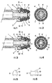
- A titre nullement limitatif, on a représenté au dessin annexé des exemples de réalisation de porte-outil perfectionnés selon l'invention, dessin sur lequel :
- - la fig. 1 est une vue en coupe axiale de l'extrémité du porte-outil en état de recevoir un foret sans entraînement par rainure axiale,
- - la fig. 2 est une vue en coupe selon la ligne II-II de la fig. 1,
- - la fig. 3 est une vue en coupe axiale de l'extrémité du porte-outil en état de recevoir un foret à rainure axiale d'entraînement,
- - la fig. 4 est une vue en coupe selon la ligne IV-IV de la fig. 3,
- - la fig. 5 est une vue en coupe transversale, à plus grande échelle, de l'entraîneur du porte-outil de la fig. 3,
- - la fig. 6 est une vue en coupe longitudinale de l'entraîneur de la fig. 5.
- Comme représenté sur les figures 1 à 4 le porte-outil 1 présente, au voisinage de son extrémité, deux cavités 2, 2′ débouchant à l'extérieur du porte-outil 1 et à l'intérieur de l'alésage axial de celui-ci. Ces cavités ont une surface intérieure en forme de cône oblong tronqué, susceptible d'épouser la forme de surface extérieure de la partie centrale de l'entraîneur associé 3. L'extrémité du porte-outil 1 est recouverte d'un capot en deux pièces 4, 4′ fixé par "clipsage" sur cette extrémité 5.
- Dans l'état représenté sur les figures 1 et 2, c'est une bille 6, 6′ qui est logée dans chacune des cavités 2, 2′ dont la forme intérieure présente des dimensions telles qu'elle permet l'introduction de la bille mais en interdit la traversée complète jusque dans l'alésage central du porte-outil. Elle permet seulement à chaque bille 6, 6′ de faire saillie dans cet alésage. Une bague 7 retient les billes dans leur logement. Elle est appliquée contre des épaulements du capuchon 4′ par un disque 8 soumis à l'action d'un ressort 9.
- Dans l'état représenté aux figures 3 et 4, la bille 6 est remplacée par le pièce 3 destinée à servir d'entraîneur en rotation de l'outil à rainure axiale.
- Cette pièce 3, en métal fritté par exemple, comporte une partie centrale 10 en forme de cône tronqué oblong qui se loge, dans jeu, dans la cavité 2 du porte-outil 1. Elle se prolonge, d'un côté, par une barrette prismatique 11 qui fait saillie dans l'alésage central du porte-outil et qui jouera le rôle d'entraîneur. Elle se prolonge, de l'autre côté, par une barrette parallélépipédique 12.
- Cette pièce 3 et la bille 6′ sont retenues par une bague 13 appliquée contre les épaulements du capuchon 4′ par un disque 14 soumis à l'action du ressort 9.
- On voit que la bague 13 se distingue de la bague 7 pour bien s'adapter à la surface de base plane de la barrette 12. Le disque 14 se distingue du disque 8 pour s'adapter lui à la surface latérale plane de la bague 13.
- Les pièces 3 en forme de barrette prismatique peuvent être façonnées de telle manière qu'elles coïncident en leurs parties 11 presque intégralement aux faces d'entraînement des rainures axiales du foret et assurent ainsi un rendement optimal de la transmission rotative.
- On voit que le porte-outil selon l'invention permet au manipulateur selon son besoin, en fonction de la configuration des forets qu'il désire utiliser dans le porte-outil d'échanger manuellement un élément de verrouillage par un élément d'entraînement.
- Le dispositif selon l'invention nécessite un nombre très limité de pièces, peu coûteuses, facilement démontables; il permet de remédier facilement à l'usure de ces éléments par un simple échange de pièces, réalisable par l'opérateur lui-même sans équipement spécifique.
Claims (2)
Applications Claiming Priority (2)
| Application Number | Priority Date | Filing Date | Title |
|---|---|---|---|
| FR8804369A FR2629376B1 (fr) | 1988-04-01 | 1988-04-01 | Porte-outil de foreuse, en particulier pour foret avec ou sans rainure d'entrainement |
| FR8804369 | 1988-04-01 |
Publications (2)
| Publication Number | Publication Date |
|---|---|
| EP0335795A1 true EP0335795A1 (fr) | 1989-10-04 |
| EP0335795B1 EP0335795B1 (fr) | 1993-09-01 |
Family
ID=9364898
Family Applications (1)
| Application Number | Title | Priority Date | Filing Date |
|---|---|---|---|
| EP89400869A Expired - Lifetime EP0335795B1 (fr) | 1988-04-01 | 1989-03-29 | Porte-outil de foreuse |
Country Status (5)
| Country | Link |
|---|---|
| US (1) | US5016892A (fr) |
| EP (1) | EP0335795B1 (fr) |
| AU (1) | AU607320B2 (fr) |
| DE (1) | DE68908751D1 (fr) |
| FR (1) | FR2629376B1 (fr) |
Cited By (2)
| Publication number | Priority date | Publication date | Assignee | Title |
|---|---|---|---|---|
| GB2395158A (en) * | 2002-11-14 | 2004-05-19 | Black & Decker Inc | Tool Holder for a Rotary Hammer |
| CN105381837A (zh) * | 2015-11-30 | 2016-03-09 | 苏州安特实业有限公司 | 一种打击锤 |
Families Citing this family (34)
| Publication number | Priority date | Publication date | Assignee | Title |
|---|---|---|---|---|
| DE4405697A1 (de) * | 1994-02-18 | 1995-08-24 | Black & Decker Inc | Werkzeugaufnahme für einen Bohr- und/oder Meißelhammer |
| US5694820A (en) * | 1995-04-17 | 1997-12-09 | Kennametal Inc. | Tool unit clamping apparatus having improved short stroke locking mechanism |
| US6000306A (en) * | 1998-06-12 | 1999-12-14 | Kennametal Inc. | Side activated tool unit clamping apparatus using mechanical advantage |
| US6102411A (en) | 1998-08-14 | 2000-08-15 | Power Tool Holders, Inc. | Chuck with locking sleeve |
| US6261035B1 (en) * | 1998-11-12 | 2001-07-17 | Black & Decker Inc. | Chuck, bit, assembly thereof and methods of mounting |
| EP1775046A3 (fr) * | 1998-11-12 | 2008-06-04 | Black & Decker, Inc. | Mandrin, meche, assemblage de ces derniers et procédés de montage |
| GB9910599D0 (en) | 1999-05-08 | 1999-07-07 | Black & Decker Inc | Rotary hammer |
| ES2219370T3 (es) | 1999-07-21 | 2004-12-01 | Black & Decker Inc. | Portabrocas accionable a motor. |
| WO2001060555A1 (fr) | 2000-02-14 | 2001-08-23 | Black & Decker Inc. | Mandrin et ensemble dote de meche |
| US6688610B2 (en) | 2000-05-12 | 2004-02-10 | Power Tool Holders Incorporated | Chuck with quick change |
| US6540237B1 (en) | 2000-06-23 | 2003-04-01 | Power Tool Holders Incorporated | Chuck |
| DE10043416A1 (de) * | 2000-09-04 | 2002-03-14 | Hilti Ag | Schlagendes Handwerkzeuggerät mit Werkzeugaufnahme |
| DE10047021A1 (de) * | 2000-09-22 | 2002-04-18 | Bosch Gmbh Robert | Handwerkzeugmachine mit einer abnehmbaren Werkzeughalterung |
| US6533291B2 (en) | 2001-02-14 | 2003-03-18 | Power Tool Holders Incorporated | Chuck having quick change mechanism |
| DE10127103B4 (de) * | 2001-06-02 | 2008-08-21 | Robert Bosch Gmbh | Werkzeughalterung |
| GB0121947D0 (en) * | 2001-09-12 | 2001-10-31 | Black & Decker Inc | Tool holder for hammer |
| US6834864B2 (en) * | 2001-10-24 | 2004-12-28 | Power Tool Holders Incorporated | Chuck having quick change mechanism |
| US6616149B1 (en) * | 2002-03-19 | 2003-09-09 | S-B Power Tool Corporation | Quick-release chuck having compact collar |
| US6929266B2 (en) * | 2002-06-18 | 2005-08-16 | Black & Decker Inc. | Bit holder |
| DE10337470A1 (de) * | 2003-08-14 | 2005-03-17 | Atlas Copco Electric Tools Gmbh | Spanneinrichtung für Sechskantbits |
| DE102004036587A1 (de) * | 2004-07-28 | 2006-03-23 | Robert Bosch Gmbh | Aufnahmevorrichtung für eine Werkzeugmaschine mit einem Werkzeughalter sowie Werkzeughalter |
| DE102005010265A1 (de) * | 2005-03-07 | 2006-09-14 | Robert Bosch Gmbh | Werkzeughalter und Handwerkzeugmaschine |
| EP2013440B1 (fr) * | 2006-04-13 | 2016-03-09 | INSTY-BIT, Inc. | Porte-meche d'outil automatique |
| JP4949886B2 (ja) * | 2007-02-16 | 2012-06-13 | 株式会社マキタ | 打撃工具のチャック機構 |
| US8262098B2 (en) * | 2008-02-05 | 2012-09-11 | Robert Bosch Gmbh | Rotary tool system with centering member |
| US8800999B2 (en) * | 2009-02-27 | 2014-08-12 | Black & Decker Inc. | Bit retention device |
| EP2883663A1 (fr) | 2013-12-13 | 2015-06-17 | HILTI Aktiengesellschaft | Procédé de fabrication d'un support d'outils |
| EP2883662A1 (fr) * | 2013-12-13 | 2015-06-17 | HILTI Aktiengesellschaft | Porte-outil |
| US11007631B2 (en) * | 2014-01-15 | 2021-05-18 | Milwaukee Electric Tool Corporation | Bit retention assembly for rotary hammer |
| EP2910338A1 (fr) * | 2014-02-20 | 2015-08-26 | HILTI Aktiengesellschaft | Porte-outil |
| JP6429121B2 (ja) * | 2015-02-09 | 2018-11-28 | パナソニックIpマネジメント株式会社 | ビットホルダ及び電動工具 |
| EP3067152A1 (fr) * | 2015-03-10 | 2016-09-14 | HILTI Aktiengesellschaft | Manchon d'entraînement dans carré conducteur |
| CN112133545B (zh) * | 2020-10-30 | 2021-08-03 | 浙江大学 | 一种变压器铁芯减振装置及方法 |
| JP7716874B2 (ja) * | 2021-04-05 | 2025-08-01 | 株式会社マキタ | 打撃工具 |
Citations (4)
| Publication number | Priority date | Publication date | Assignee | Title |
|---|---|---|---|---|
| FR1588841A (fr) * | 1967-07-24 | 1970-03-16 | ||
| FR2331410A1 (fr) * | 1975-11-14 | 1977-06-10 | Bosch Gmbh Robert | Dispositif pour la transmission de couples de rotation |
| FR2346084A1 (fr) * | 1976-04-02 | 1977-10-28 | Bater Gmbh Maschf Otto | Porte-outil pour perceuse a percussion et analogues |
| EP0223738A2 (fr) * | 1985-11-11 | 1987-05-27 | HILTI Aktiengesellschaft | Dispositif de fixation pour outils de forage et de burinage |
Family Cites Families (8)
| Publication number | Priority date | Publication date | Assignee | Title |
|---|---|---|---|---|
| US1283173A (en) * | 1916-04-13 | 1918-10-29 | Christian F Heinkel | Chuck. |
| US2386469A (en) * | 1944-01-10 | 1945-10-09 | Shatterproof Glass Corp | Chuck |
| BE480077A (fr) * | 1947-12-24 | |||
| DE874855C (de) * | 1950-06-04 | 1953-04-27 | Karl Heyer | Schnellwechselfutter fuer Werkzeugmaschinen, insbesondere Bohrmaschinen, Fraesmaschinen, Drehbaenke |
| AT343831B (de) * | 1975-11-12 | 1978-06-26 | Voest Ag | Stutz- und fuhrungsbogen fur gussstrange |
| DE3330486A1 (de) * | 1983-08-24 | 1985-03-07 | Wera Werk Hermann Werner Gmbh & Co, 5600 Wuppertal | Spannfutter fuer werkzeug-einsatzstuecke, insbesondere schraubendreherbits |
| DE3536132A1 (de) * | 1985-10-10 | 1987-04-16 | Bosch Gmbh Robert | Werkzeughalter |
| DE3637354A1 (de) * | 1986-11-03 | 1988-05-05 | Bosch Gmbh Robert | Werkzeughalter |
-
1988
- 1988-04-01 FR FR8804369A patent/FR2629376B1/fr not_active Expired - Fee Related
-
1989
- 1989-03-29 US US07/330,014 patent/US5016892A/en not_active Expired - Fee Related
- 1989-03-29 DE DE89400869T patent/DE68908751D1/de not_active Expired - Lifetime
- 1989-03-29 EP EP89400869A patent/EP0335795B1/fr not_active Expired - Lifetime
- 1989-03-31 AU AU32357/89A patent/AU607320B2/en not_active Ceased
Patent Citations (4)
| Publication number | Priority date | Publication date | Assignee | Title |
|---|---|---|---|---|
| FR1588841A (fr) * | 1967-07-24 | 1970-03-16 | ||
| FR2331410A1 (fr) * | 1975-11-14 | 1977-06-10 | Bosch Gmbh Robert | Dispositif pour la transmission de couples de rotation |
| FR2346084A1 (fr) * | 1976-04-02 | 1977-10-28 | Bater Gmbh Maschf Otto | Porte-outil pour perceuse a percussion et analogues |
| EP0223738A2 (fr) * | 1985-11-11 | 1987-05-27 | HILTI Aktiengesellschaft | Dispositif de fixation pour outils de forage et de burinage |
Cited By (4)
| Publication number | Priority date | Publication date | Assignee | Title |
|---|---|---|---|---|
| GB2395158A (en) * | 2002-11-14 | 2004-05-19 | Black & Decker Inc | Tool Holder for a Rotary Hammer |
| GB2395158B (en) * | 2002-11-14 | 2005-11-16 | Black & Decker Inc | Tool holder for a rotary hammer |
| US7338051B2 (en) | 2002-11-14 | 2008-03-04 | Black & Decker Inc. | Tool holder for a rotary hammer |
| CN105381837A (zh) * | 2015-11-30 | 2016-03-09 | 苏州安特实业有限公司 | 一种打击锤 |
Also Published As
| Publication number | Publication date |
|---|---|
| FR2629376B1 (fr) | 1994-04-29 |
| FR2629376A1 (fr) | 1989-10-06 |
| DE68908751D1 (de) | 1993-10-07 |
| AU3235789A (en) | 1989-10-05 |
| EP0335795B1 (fr) | 1993-09-01 |
| US5016892A (en) | 1991-05-21 |
| AU607320B2 (en) | 1991-02-28 |
Similar Documents
| Publication | Publication Date | Title |
|---|---|---|
| EP0335795B1 (fr) | Porte-outil de foreuse | |
| FR2508359A1 (fr) | Porte-outil pour perceuses et perceuses a percussion | |
| US4621820A (en) | Percussion drilling apparatus | |
| FR2564027A1 (fr) | Mandrin de serrage pour un outil de percage a percussion | |
| FR2845108A1 (fr) | Ensemble de verrou reconfigurable et procede de fonctionnement de cet ensemble | |
| FR2511290A1 (fr) | Porte-outil pour marteau perforateur | |
| FR2564345A1 (fr) | Mandrin porte-outil pour instruments a main | |
| ES2444417T3 (es) | Llave de accionamiento de una cerradura de resistencia a los choques mejorada | |
| JPS62114887A (ja) | 工具保持器 | |
| JP4256539B2 (ja) | ドリル及び/又はたがね装置の工具ホルダ | |
| US5009440A (en) | Tool chuck for tool bits | |
| CH690905A5 (fr) | Procédé et dispositif de raccordement et instrument chirurgical pour l'entraînement d'outils rotatif interchangeables. | |
| FR2872071A1 (fr) | Dispositif comportant une unite de limitation de couple | |
| FR2543035A1 (fr) | Mandrin porte-outil pour appareils portatifs | |
| FR2560101A1 (fr) | Mandrin de serrage pour un outil de percage a percussion | |
| US4607855A (en) | Hammer drill chuck | |
| FR2564026A1 (fr) | Mandrin de serrage pour un outil, en particulier pour le percage a percussion. | |
| JPS6347002A (ja) | 工具チャック | |
| FR2471276A1 (fr) | ||
| EP0573766A1 (fr) | Mandrin universel pour une machine de perçage d'un trou de coulée d'un four á cuve | |
| FR2552362A1 (fr) | Mandrin de serrage pour un outil de percage a percussion | |
| EP0005384A1 (fr) | Marteau pneumatique fond-de-trou comportant un taillant | |
| JP4063979B2 (ja) | 岩石のための回転衝撃式穿孔用ドリル | |
| EP1694470B1 (fr) | Dispositif d'assemblage du carter et du corps d'un brise-roche hydraulique | |
| CA2548114A1 (fr) | Dispositif de retenue d'une clavette d'outil pour appareil de demolition a percussion |
Legal Events
| Date | Code | Title | Description |
|---|---|---|---|
| PUAI | Public reference made under article 153(3) epc to a published international application that has entered the european phase |
Free format text: ORIGINAL CODE: 0009012 |
|
| AK | Designated contracting states |
Kind code of ref document: A1 Designated state(s): DE ES FR GB IT NL SE |
|
| 17P | Request for examination filed |
Effective date: 19900326 |
|
| 17Q | First examination report despatched |
Effective date: 19910610 |
|
| GRAA | (expected) grant |
Free format text: ORIGINAL CODE: 0009210 |
|
| AK | Designated contracting states |
Kind code of ref document: B1 Designated state(s): DE ES FR GB IT NL SE |
|
| PG25 | Lapsed in a contracting state [announced via postgrant information from national office to epo] |
Ref country code: IT Free format text: LAPSE BECAUSE OF FAILURE TO SUBMIT A TRANSLATION OF THE DESCRIPTION OR TO PAY THE FEE WITHIN THE PRE;WARNING: LAPSES OF ITALIAN PATENTS WITH EFFECTIVE DATE BEFORE 2007 MAY HAVE OCCURRED AT ANY TIME BEFORE 2007. THE CORRECT EFFECTIVE DATE MAY BE DIFFERENT FROM THE ONE RECORDED.SCRIBED TIME-LIMIT Effective date: 19930901 Ref country code: NL Effective date: 19930901 Ref country code: DE Effective date: 19930901 Ref country code: GB Effective date: 19930901 Ref country code: SE Effective date: 19930901 |
|
| REF | Corresponds to: |
Ref document number: 68908751 Country of ref document: DE Date of ref document: 19931007 |
|
| PG25 | Lapsed in a contracting state [announced via postgrant information from national office to epo] |
Ref country code: ES Free format text: LAPSE BECAUSE OF FAILURE TO SUBMIT A TRANSLATION OF THE DESCRIPTION OR TO PAY THE FEE WITHIN THE PRESCRIBED TIME-LIMIT Effective date: 19931212 |
|
| NLV1 | Nl: lapsed or annulled due to failure to fulfill the requirements of art. 29p and 29m of the patents act | ||
| GBV | Gb: ep patent (uk) treated as always having been void in accordance with gb section 77(7)/1977 [no translation filed] |
Effective date: 19930901 |
|
| PLBE | No opposition filed within time limit |
Free format text: ORIGINAL CODE: 0009261 |
|
| STAA | Information on the status of an ep patent application or granted ep patent |
Free format text: STATUS: NO OPPOSITION FILED WITHIN TIME LIMIT |
|
| 26N | No opposition filed | ||
| PGFP | Annual fee paid to national office [announced via postgrant information from national office to epo] |
Ref country code: ES Payment date: 19960315 Year of fee payment: 8 |
|
| PGFP | Annual fee paid to national office [announced via postgrant information from national office to epo] |
Ref country code: FR Payment date: 19980221 Year of fee payment: 10 |
|
| PG25 | Lapsed in a contracting state [announced via postgrant information from national office to epo] |
Ref country code: FR Free format text: LAPSE BECAUSE OF NON-PAYMENT OF DUE FEES Effective date: 19991130 |
|
| REG | Reference to a national code |
Ref country code: FR Ref legal event code: ST |