EP0335820A1 - Kompakte RF-angeregter Wellenleiter-Gas-Laser-Einrichtung mit verteilten Induktoren - Google Patents
Kompakte RF-angeregter Wellenleiter-Gas-Laser-Einrichtung mit verteilten Induktoren Download PDFInfo
- Publication number
- EP0335820A1 EP0335820A1 EP89630066A EP89630066A EP0335820A1 EP 0335820 A1 EP0335820 A1 EP 0335820A1 EP 89630066 A EP89630066 A EP 89630066A EP 89630066 A EP89630066 A EP 89630066A EP 0335820 A1 EP0335820 A1 EP 0335820A1
- Authority
- EP
- European Patent Office
- Prior art keywords
- electrode
- laser arrangement
- inductor coils
- waveguide
- housing
- Prior art date
- Legal status (The legal status is an assumption and is not a legal conclusion. Google has not performed a legal analysis and makes no representation as to the accuracy of the status listed.)
- Granted
Links
- 125000006850 spacer group Chemical group 0.000 claims abstract description 20
- 239000003990 capacitor Substances 0.000 claims description 2
- 239000007769 metal material Substances 0.000 claims description 2
- 238000010276 construction Methods 0.000 description 13
- 230000005284 excitation Effects 0.000 description 10
- 238000003825 pressing Methods 0.000 description 10
- 238000013459 approach Methods 0.000 description 5
- XAGFODPZIPBFFR-UHFFFAOYSA-N aluminium Chemical compound [Al] XAGFODPZIPBFFR-UHFFFAOYSA-N 0.000 description 3
- 229910052782 aluminium Inorganic materials 0.000 description 3
- 238000004519 manufacturing process Methods 0.000 description 3
- 238000013461 design Methods 0.000 description 2
- 238000004070 electrodeposition Methods 0.000 description 2
- 238000010894 electron beam technology Methods 0.000 description 2
- 230000003287 optical effect Effects 0.000 description 2
- 238000003466 welding Methods 0.000 description 2
- 238000005452 bending Methods 0.000 description 1
- 238000004891 communication Methods 0.000 description 1
- 230000005684 electric field Effects 0.000 description 1
- 230000005672 electromagnetic field Effects 0.000 description 1
- 238000009713 electroplating Methods 0.000 description 1
- 238000001125 extrusion Methods 0.000 description 1
- 239000012634 fragment Substances 0.000 description 1
- 238000010348 incorporation Methods 0.000 description 1
- 239000007788 liquid Substances 0.000 description 1
- 238000003754 machining Methods 0.000 description 1
- 238000000034 method Methods 0.000 description 1
- 230000003071 parasitic effect Effects 0.000 description 1
- 230000001902 propagating effect Effects 0.000 description 1
- 238000007789 sealing Methods 0.000 description 1
- 238000001228 spectrum Methods 0.000 description 1
- 238000012546 transfer Methods 0.000 description 1
Images
Classifications
-
- H—ELECTRICITY
- H01—ELECTRIC ELEMENTS
- H01S—DEVICES USING THE PROCESS OF LIGHT AMPLIFICATION BY STIMULATED EMISSION OF RADIATION [LASER] TO AMPLIFY OR GENERATE LIGHT; DEVICES USING STIMULATED EMISSION OF ELECTROMAGNETIC RADIATION IN WAVE RANGES OTHER THAN OPTICAL
- H01S3/00—Lasers, i.e. devices using stimulated emission of electromagnetic radiation in the infrared, visible or ultraviolet wave range
- H01S3/02—Constructional details
- H01S3/03—Constructional details of gas laser discharge tubes
- H01S3/0315—Waveguide lasers
Definitions
- the present invention relates to waveguide gas lasers in general, and more particularly to a distributed inductance RF-excited waveguide gas laser arrangement having a very compact construction.
- waveguide gas lasers there are already known various constructions of waveguide gas lasers, among them such in which the lasing gas which is contained in a waveguiding laser cavity is excited by an electromagnetic field that is applied transversely of the laser cavity between a "hot” electrode and a ground electrode and that oscillates at a frequency in the radio frequency (RF) range.
- RF radio frequency
- Still another object of the present invention is so to develop the laser arrangement of the type here under consideration as to achieve substantially uniform excitation of the discharge across the waveguiding laser cavity having a length considerably in excess of one-fourth of the excitation wavelength.
- a concomitant object of the present invention is design the laser arrangement of the above type in such a manner as to be relatively simple in construction, inexpensive to manufacture, easy to use, and yet reliable in operation.
- a waveguide laser arrangement which comprises a housing bounding an internal space.
- a laser stack is accommodated in the internal space and includes a first electrode having a major surface situated in and facing into the internal space; a dielectric waveguide body juxtaposed with the major surface of the first electrode and bounding at least one elongated laser cavity; a second electrode juxtaposed with the waveguide body across the laser cavity from, and forming a capacitor of a predetermined capacitance with, the first electrode; a dielectric spacer body juxtaposed with the second electrode across from the waveguide body and having one major surface facing toward, and another major surface facing away from, the second electrode; and distributed inductance means including a plurality of flat inductor coils distributed longitudinally of the laser cavity along and in juxtaposition with the other major surface of the spacer body and each having spaced first and second ends and a predetermined electric inductance between the ends.
- the laser arrangement further includes means for supplying a first electric potential to the first electrode and a second electric potential to the second electrode, at least one of the electric potentials alternating at a predetermined frequency relative to the other; and first and second connecting means for electrically connecting the first and second ends of each of the inductor coils with the first and second electrode, respectively, with attendant inclusion of the inductances of the inductor coils electrically in parallel with the capacitance.
- a particular advantage of the arrangement of the present invention that is constructed in the above manner is that, due to the construction of the inductor coils as flat elements that extend along the respective major surface of the spacer body, it was possible to significantly reduce the overall height of the laser arrangement, and to make the inductor coils as integral parts of a separate flat inductor member or even as strips formed directly on the spacer body and thus considerably reduce the number of parts of the laser arrangement.
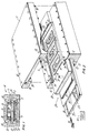
- the reference numeral 10 has been used therein to identify a distributed inductance RF-excited waveguide gas laser arrangement of the present invention in its entirety.
- the laser arrangement 10 includes as one of its components a metallic housing 11. It is currently preferred to make the housing 11 of aluminum, and particularly as an aluminum extrusion.
- the housing 11 circumferentially bounds an internal space 12 which includes a first, larger portion 13 and a second, smaller portion 14 which is in open communication with the larger portion 13.
- the larger portion 13 of the internal space 12 is bounded by a bottom wall 15, two side walls 16 and 17, and incompletely by two top wall portions 18 and 19 of the housing 11, while the smaller portion 14 of the internal space 12 is bounded by two side walls 20 and 21 which are respectively integral with the top wall portions 18 and 19, and a top wall 22 which is integral with and interconnects the side walls 20 and 21.
- the larger portion 13 of the internal space 12 accommodates a waveguide laser assembly 23 which includes, from bottom to top, a dielectric waveguide member or body 24 provided with waveguiding laser channels or cavities 25, a dielectric cover 26 for the waveguide member 24, a "hot” or active electrode 27, a dielectric spacer slab 28, and a distributed inductor member 29.
- the housing 11 is at ground potential so that a raised portion 30 of the bottom wall 15 of the housing 11 constitutes a ground electrode. Because of this use of the raised portion 30, it is possible to dispense with the heretofore customary separate ground electrode, as a result of which the dimensions and particularly the height of the laser arrangement can be significantly reduced in comparison to heretofore used constructions.
- the laser arrangement 10 further includes a pressing member or top 31 that is connected to the housing 11 by respective recessed-head screws as illustrated, or by similar threaded fasteners 32.
- the pressing member 31 has a recess 33 which accommodates the walls 20 to 22 of the housing 11 with a clearance therefrom.
- the clearance or gap between the pressing member 31 and the walls 20 to 22 of the housing 11 has such a magnitude that, even when the threaded fasteners 32 are tightened to the full extent possible, the pressing member 31 will still not contact the walls 20 to 22.
- the wall portions 18 and 19 will be pressed against the distributed inductor member 29 and the components 24 and 26 to 29 of the waveguide laser unit 23 will be pressed against one another and against the projecting portion 30 of the bottom wall 15 of the housing 11, thus eliminating any gaps between the housing 11 and the waveguide laser unit 23, as well as between the individual directly superimposed components 24 and 26 to 29 of the waveguide laser unit 23 and firmly holding the waveguide laser unit 23 and its components 24 and 26 to 29 in their respective positions.
- the tightening of the threaded fasteners 32 and the attendant deformation of the wall portions 18 and 19 of the housing 11 also result in the establishment of good electrical contact between the wall portions 18 and 19 and respective marginal portions 34 and 35 of the distributed inductance member 29 which are thus clamped between the wall portions 18 and 19 of the housing 11 and the dielectric slab 28.
- the marginal portions 34 and 35 of the distributed inductance member 29 are at the ground potential as well.
- the pressing member 31 may be provided, if so desired, with respective heat-exchange passages 36, 37 and 38 through which a heat-exchange medium, especially a heat-exchange liquid, is being circulated to control the temperature of the pressing member 31 and, by conduction, also of the upper region of the housing 11.
- a heat-exchange medium especially a heat-exchange liquid
- at least the bottom wall 15 of the housing 11 is usually in contact with a heat sink, so that heat is removed at least from the bottom portion of the housing 11 in this manner.
- the channel 25 of the waveguiding member 24 has been indicated to extend along a Z-shaped course, the waveguiding member 24 could be provided with channels extending along other courses, such as parallel ones, and the adjacent channels 25 could communicate with one another over at least parts of their lengths and heights to achieve phase locking between and among the laser beams propagating in such channels 25.
- the marginal portions 34 and 35 of the distributed inductor member 29 are configured as current-conducting rails that extend in the longitudinal direction of the laser arrangement 10.
- the distributed inductor member 29 further includes a plurality of flat inductor coils 40 alternating ones of which are connected with the marginal portions 34 and 35, respectively, coil in opposite senses, and have respective free ends 41 which are connected, such as by electron beam welding, to respective electrically conductive pins 42 which, in turn, are connected, such as again by electron beam welding, with the "hot" electrode 27.
- the dielectric slab 28 is provided with a plurality of holes 43 for the passage of the respective pins 42 therethrough.
- the electrode 27 is supplied, in a manner that is well known to those active in this field and which is indicated in Figure 2 only diagrammatically by a power source 44 and an electric supply line 45, with an alternating electric current at a frequency preferably in the radio frequency range of the spectrum, so that the electrode 27 and the bottom wall 15 of the housing 11 or its projecting portion 30 form a capacitance, and laser excitation takes place in the channels 25 of the waveguide plate 24.
- the inductor coils 40 are electrically arranged in parallel to one another and also in parallel to the aforementioned capacitance. In this manner, the inductance of the inductor coils 40 is effectively distributed over the length of the waveguide laser unit or assembly 23 as needed for efficient operation of the laser arrangement 10.
- the inductances of the inductor coils 40 are such that the inductor coils 40 are in or close to resonance with the aforementioned capacitance at the frequency at which the current supplied to the electrode 27 oscillates.
- the pins 42 mechanically connect the distributed inductor member 29 with the electrode 28 and are sufficiently strong to form an essentially rigid structure which is self-supporting even in the absence of the dielectric slab or spacer 28.
- the self-supporting properties of this rigid structure are further improved when, as indicated in Figure 2 of the drawing, the current-conducting rails 34 and 35 are interconnected at least at the longitudinal end portions of the arrangement 10, by respective interconnecting portions, such as 46.
- the "hot" electrode 27 and the distributed inductor member 29 could be provided directly and integrally on the slab 28 as respective metallic strips or layers, for instance by resorting to the well-known electroplating or electrodeposition techniques, and be connected with one another by electrically conductive pins or the like embedded in, or accommodated in holes of, the dielectric slab or spacer 28.
- the inductor coils 40 as discrete portions of the separate member 29 which may be obtained by stamping, machining or in a similar manner from a relatively thin plate of a metallic material, such as aluminum, there is obtained a desirable further reduction in the height of the laser arrangement 10 on top of that obtained as a result of the incorporation of the ground electrode into the housing 11 as a raised portion 30 thereof.
- the height of the laser arrangement 10 may be further reduced when the electrode 27 and the distributed inductor member 29 are provided directly on the slab 28 by electrodeposition or the like.
- a further important advantage of the construction of the laser arrangement 10 in accordance with the present invention is that the number of parts of the laser arrangement 10 and especially of those parts that are to be axially introduced into the larger portion 13 of the internal space during the assembly of the laser arrangement 10 is drastically reduced as compared to those laser arrangement constructions which are being currently used where the inductors and the mounting and connecting elements associated therewith are constructed as separate parts.
- the number of elements contained in the stack or laser unit 23 is reduced from forty or more in a heretofore used construction to four or less in the construction embodying the present invention.
Landscapes
- Physics & Mathematics (AREA)
- Electromagnetism (AREA)
- Engineering & Computer Science (AREA)
- Plasma & Fusion (AREA)
- Optics & Photonics (AREA)
- Lasers (AREA)
Applications Claiming Priority (2)
| Application Number | Priority Date | Filing Date | Title |
|---|---|---|---|
| US07/173,790 US4787090A (en) | 1988-03-28 | 1988-03-28 | Compact distributed inductance RF-excited waveguide gas laser arrangement |
| US173790 | 1993-12-27 |
Publications (2)
| Publication Number | Publication Date |
|---|---|
| EP0335820A1 true EP0335820A1 (de) | 1989-10-04 |
| EP0335820B1 EP0335820B1 (de) | 1993-08-11 |
Family
ID=22633503
Family Applications (1)
| Application Number | Title | Priority Date | Filing Date |
|---|---|---|---|
| EP89630066A Expired - Lifetime EP0335820B1 (de) | 1988-03-28 | 1989-03-28 | Kompakte RF-angeregter Wellenleiter-Gas-Laser-Einrichtung mit verteilten Induktoren |
Country Status (4)
| Country | Link |
|---|---|
| US (1) | US4787090A (de) |
| EP (1) | EP0335820B1 (de) |
| JP (1) | JPH0210783A (de) |
| DE (1) | DE68908230T2 (de) |
Families Citing this family (30)
| Publication number | Priority date | Publication date | Assignee | Title |
|---|---|---|---|---|
| US5231644A (en) * | 1990-09-26 | 1993-07-27 | Siemens Aktiengesellschaft | Slab or stripline gas laser |
| US5105430A (en) * | 1991-04-09 | 1992-04-14 | The United States Of America As Represented By The United States Department Of Energy | Thin planar package for cooling an array of edge-emitting laser diodes |
| US5381436A (en) * | 1993-05-28 | 1995-01-10 | Honeywell, Inc. | Ring laser gyro employing radio frequency for pumping of gain medium |
| GB9316282D0 (en) * | 1993-08-05 | 1993-09-22 | Univ Heriot Watt | Uniformly excited radiofrequency gas discharge of large electrode area |
| EP0687044B1 (de) | 1994-06-08 | 1998-04-01 | QSource, Inc. | Gaslaser mit rechteckigem Entladungsraum |
| US5661746A (en) * | 1995-10-17 | 1997-08-26 | Universal Laser Syatems, Inc. | Free-space gas slab laser |
| ATE226766T1 (de) | 1995-11-27 | 2002-11-15 | Qsource Inc | Gaslaser mit rechteckigem entladungsraum |
| DE69840287D1 (de) | 1997-03-14 | 2009-01-15 | Demaria Electrooptics Inc | Hochfrequenz-angeregter wellenleiterlaser |
| US5881087A (en) * | 1997-04-30 | 1999-03-09 | Universal Laser Systems, Inc. | Gas laser tube design |
| US5901167A (en) * | 1997-04-30 | 1999-05-04 | Universal Laser Systems, Inc. | Air cooled gas laser |
| US5867517A (en) * | 1997-04-30 | 1999-02-02 | Universal Laser Systems, Inc. | Integrated gas laser RF feed and fill apparatus and method |
| US6370178B1 (en) * | 1998-12-21 | 2002-04-09 | Imed Lasers | Wide area laser and multi-pass laser optical cavity for use therein |
| WO2001086767A1 (en) * | 2000-05-08 | 2001-11-15 | Coherent Deos | A method and apparatus for increasing the power of a waveguide laser |
| US6788722B1 (en) | 2000-07-10 | 2004-09-07 | Coherent, Inc. | High power waveguide laser |
| US6697408B2 (en) | 2001-04-04 | 2004-02-24 | Coherent, Inc. | Q-switched cavity dumped CO2 laser for material processing |
| DE60234823D1 (de) * | 2001-04-04 | 2010-02-04 | Coherent Deos | Gütegeschalteter co2 laser für materialbearbeitung |
| US6784399B2 (en) * | 2001-05-09 | 2004-08-31 | Electro Scientific Industries, Inc. | Micromachining with high-energy, intra-cavity Q-switched CO2 laser pulses |
| US6983001B2 (en) * | 2002-12-16 | 2006-01-03 | Universal Laser Systems, Inc. | Laser with heat transfer system |
| US7039079B2 (en) * | 2003-03-14 | 2006-05-02 | Coherent, Inc. | Pulsed CO2 laser including an optical damage resistant electro-optical switching arrangement |
| US7050475B2 (en) * | 2003-05-02 | 2006-05-23 | Litelaser Llc | Waveguide laser |
| US7583717B2 (en) * | 2004-08-30 | 2009-09-01 | Videojet Technologies Inc | Laser system |
| US7296359B2 (en) * | 2004-10-27 | 2007-11-20 | Videojet Technologies | Laser alignment system and method |
| WO2008045019A2 (en) * | 2005-08-11 | 2008-04-17 | Coherent, Inc. | Pulsed rf high pressure co2 lasers |
| US7570683B1 (en) | 2006-03-01 | 2009-08-04 | Epilog Corporation | Waveguided laser channels for a gas laser |
| ITFI20070142A1 (it) * | 2007-06-26 | 2008-12-27 | El En Spa | "sorgente laser a gas eccitata in radiofrequenza" |
| US8942270B2 (en) | 2008-02-22 | 2015-01-27 | Coherent, Inc. | Diffusion-cooled CO2 laser with flexible housing |
| GB2552636B (en) | 2017-11-22 | 2019-01-09 | Rofin Sinar Uk Ltd | Polarisation and mode selection technique for a laser |
| CN111788747B (zh) | 2018-01-29 | 2024-02-27 | Idea机器显影设计及生产有限公司 | 紧凑型同轴激光器 |
| US10644474B2 (en) * | 2018-03-07 | 2020-05-05 | Coherent, Inc. | Conductively-cooled slab laser |
| ES2966706T3 (es) | 2020-02-05 | 2024-04-24 | Coherent Inc | Láser de gas excitado por radiofrecuencia |
Citations (4)
| Publication number | Priority date | Publication date | Assignee | Title |
|---|---|---|---|---|
| US4363126A (en) * | 1980-12-10 | 1982-12-07 | United Technologies Corporation | Tuned-circuit RF-excited laser |
| FR2559966A1 (fr) * | 1984-02-18 | 1985-08-23 | Ferranti Plc | Laser a guide d'ondes |
| US4688228A (en) * | 1985-08-06 | 1987-08-18 | United Technologies Corporation | Phase locked dielectric ridge gas laser |
| US4719640A (en) * | 1985-08-01 | 1988-01-12 | The United States Of America As Represented By The Secretary Of The Army | Multiple parallel RF excited CO2 lasers |
Family Cites Families (1)
| Publication number | Priority date | Publication date | Assignee | Title |
|---|---|---|---|---|
| US4438514A (en) * | 1982-02-16 | 1984-03-20 | United Technologies Corporation | Sure-start waveguide laser |
-
1988
- 1988-03-28 US US07/173,790 patent/US4787090A/en not_active Expired - Lifetime
-
1989
- 1989-03-27 JP JP1074783A patent/JPH0210783A/ja active Pending
- 1989-03-28 EP EP89630066A patent/EP0335820B1/de not_active Expired - Lifetime
- 1989-03-28 DE DE89630066T patent/DE68908230T2/de not_active Expired - Fee Related
Patent Citations (4)
| Publication number | Priority date | Publication date | Assignee | Title |
|---|---|---|---|---|
| US4363126A (en) * | 1980-12-10 | 1982-12-07 | United Technologies Corporation | Tuned-circuit RF-excited laser |
| FR2559966A1 (fr) * | 1984-02-18 | 1985-08-23 | Ferranti Plc | Laser a guide d'ondes |
| US4719640A (en) * | 1985-08-01 | 1988-01-12 | The United States Of America As Represented By The Secretary Of The Army | Multiple parallel RF excited CO2 lasers |
| US4688228A (en) * | 1985-08-06 | 1987-08-18 | United Technologies Corporation | Phase locked dielectric ridge gas laser |
Also Published As
| Publication number | Publication date |
|---|---|
| EP0335820B1 (de) | 1993-08-11 |
| US4787090A (en) | 1988-11-22 |
| DE68908230T2 (de) | 1993-11-25 |
| DE68908230D1 (de) | 1993-09-16 |
| JPH0210783A (ja) | 1990-01-16 |
Similar Documents
| Publication | Publication Date | Title |
|---|---|---|
| EP0335820B1 (de) | Kompakte RF-angeregter Wellenleiter-Gas-Laser-Einrichtung mit verteilten Induktoren | |
| US5953360A (en) | All metal electrode sealed gas laser | |
| US4688228A (en) | Phase locked dielectric ridge gas laser | |
| US7263116B2 (en) | Dielectric coupled CO2 slab laser | |
| US20090004918A1 (en) | Rf shielded, series inductor, high rf power impedance matching interconnector for co2 slab laser | |
| US4807232A (en) | Phase locked staggered dielectric ridge array waveguide gas laser | |
| US4481634A (en) | RF Excited metal waveguide laser | |
| US4890294A (en) | Plasma apparatus | |
| US4513424A (en) | Laser pumped by X-band microwaves | |
| US7197060B2 (en) | Waveguide laser | |
| US5475703A (en) | Radio frequency-excited gas laser | |
| US4807234A (en) | Phase locked alternating dielectric ridge gas laser | |
| US7894500B1 (en) | Non-linear waveguided laser channel for a gas laser | |
| KR910002239B1 (ko) | 레이저 장치 | |
| US4807233A (en) | Phase locked cusp-shaped dielectric ridge gas laser | |
| US5079773A (en) | Tailored cross section optical waveguide laser array | |
| US7126973B2 (en) | One dimensional all-metal slab waveguide gas laser | |
| US5379317A (en) | Microwave-excited slab waveguide laser with all metal sealed cavity | |
| US6711201B2 (en) | Truncated ridge waveguide for all-metal gas laser excitation | |
| US5596593A (en) | Orthogonal RFDC transverse excited gas laser | |
| EP3763003B1 (de) | Leitungsgekühlter slablaser | |
| EP0222016B1 (de) | Rf-erregter hochleistungsgaslaser mit transversalentladung | |
| US5127017A (en) | Electrically excited stripline laser | |
| DE69707343T2 (de) | Multikanal, RF-angeregte Gasentladungslaservorrichtung | |
| WO1996037935A1 (en) | Microwave excited laser with uniform gas discharge |
Legal Events
| Date | Code | Title | Description |
|---|---|---|---|
| PUAI | Public reference made under article 153(3) epc to a published international application that has entered the european phase |
Free format text: ORIGINAL CODE: 0009012 |
|
| AK | Designated contracting states |
Kind code of ref document: A1 Designated state(s): CH DE FR GB LI |
|
| 17P | Request for examination filed |
Effective date: 19891115 |
|
| 17Q | First examination report despatched |
Effective date: 19920220 |
|
| GRAA | (expected) grant |
Free format text: ORIGINAL CODE: 0009210 |
|
| AK | Designated contracting states |
Kind code of ref document: B1 Designated state(s): CH DE FR GB LI |
|
| ET | Fr: translation filed | ||
| REF | Corresponds to: |
Ref document number: 68908230 Country of ref document: DE Date of ref document: 19930916 |
|
| PGFP | Annual fee paid to national office [announced via postgrant information from national office to epo] |
Ref country code: FR Payment date: 19940209 Year of fee payment: 6 |
|
| PGFP | Annual fee paid to national office [announced via postgrant information from national office to epo] |
Ref country code: CH Payment date: 19940211 Year of fee payment: 6 |
|
| PGFP | Annual fee paid to national office [announced via postgrant information from national office to epo] |
Ref country code: GB Payment date: 19940216 Year of fee payment: 6 |
|
| PGFP | Annual fee paid to national office [announced via postgrant information from national office to epo] |
Ref country code: DE Payment date: 19940217 Year of fee payment: 6 |
|
| PLBE | No opposition filed within time limit |
Free format text: ORIGINAL CODE: 0009261 |
|
| STAA | Information on the status of an ep patent application or granted ep patent |
Free format text: STATUS: NO OPPOSITION FILED WITHIN TIME LIMIT |
|
| 26N | No opposition filed | ||
| PG25 | Lapsed in a contracting state [announced via postgrant information from national office to epo] |
Ref country code: GB Effective date: 19950328 |
|
| PG25 | Lapsed in a contracting state [announced via postgrant information from national office to epo] |
Ref country code: LI Effective date: 19950331 Ref country code: CH Effective date: 19950331 |
|
| GBPC | Gb: european patent ceased through non-payment of renewal fee |
Effective date: 19950328 |
|
| PG25 | Lapsed in a contracting state [announced via postgrant information from national office to epo] |
Ref country code: FR Free format text: LAPSE BECAUSE OF NON-PAYMENT OF DUE FEES Effective date: 19951130 |
|
| REG | Reference to a national code |
Ref country code: CH Ref legal event code: PL |
|
| PG25 | Lapsed in a contracting state [announced via postgrant information from national office to epo] |
Ref country code: DE Effective date: 19951201 |
|
| REG | Reference to a national code |
Ref country code: FR Ref legal event code: ST |