EP0336016B1 - Joint à fluide magnétique - Google Patents
Joint à fluide magnétique Download PDFInfo
- Publication number
- EP0336016B1 EP0336016B1 EP88121078A EP88121078A EP0336016B1 EP 0336016 B1 EP0336016 B1 EP 0336016B1 EP 88121078 A EP88121078 A EP 88121078A EP 88121078 A EP88121078 A EP 88121078A EP 0336016 B1 EP0336016 B1 EP 0336016B1
- Authority
- EP
- European Patent Office
- Prior art keywords
- gap
- seal
- ferrofluid
- seal according
- sealing rings
- Prior art date
- Legal status (The legal status is an assumption and is not a legal conclusion. Google has not performed a legal analysis and makes no representation as to the accuracy of the status listed.)
- Expired - Lifetime
Links
- 238000007789 sealing Methods 0.000 title claims abstract description 30
- 239000011554 ferrofluid Substances 0.000 title claims abstract description 22
- 125000006850 spacer group Chemical group 0.000 claims description 4
- 238000010276 construction Methods 0.000 claims 1
- 230000000717 retained effect Effects 0.000 claims 1
- 239000007788 liquid Substances 0.000 description 11
- 238000006073 displacement reaction Methods 0.000 description 9
- BGPVFRJUHWVFKM-UHFFFAOYSA-N N1=C2C=CC=CC2=[N+]([O-])C1(CC1)CCC21N=C1C=CC=CC1=[N+]2[O-] Chemical compound N1=C2C=CC=CC2=[N+]([O-])C1(CC1)CCC21N=C1C=CC=CC1=[N+]2[O-] BGPVFRJUHWVFKM-UHFFFAOYSA-N 0.000 description 4
- 239000000463 material Substances 0.000 description 3
- 229910000831 Steel Inorganic materials 0.000 description 2
- 230000004323 axial length Effects 0.000 description 2
- 238000009434 installation Methods 0.000 description 2
- 238000000034 method Methods 0.000 description 2
- 239000010959 steel Substances 0.000 description 2
- 239000011248 coating agent Substances 0.000 description 1
- 238000000576 coating method Methods 0.000 description 1
- 230000006835 compression Effects 0.000 description 1
- 238000007906 compression Methods 0.000 description 1
- 230000006378 damage Effects 0.000 description 1
- 230000007423 decrease Effects 0.000 description 1
- 230000005489 elastic deformation Effects 0.000 description 1
- 239000013013 elastic material Substances 0.000 description 1
- 238000005516 engineering process Methods 0.000 description 1
- 239000012634 fragment Substances 0.000 description 1
- 230000007774 longterm Effects 0.000 description 1
- 239000000696 magnetic material Substances 0.000 description 1
- 230000013011 mating Effects 0.000 description 1
- 239000002184 metal Substances 0.000 description 1
- 239000002991 molded plastic Substances 0.000 description 1
- 230000035515 penetration Effects 0.000 description 1
- 239000004033 plastic Substances 0.000 description 1
- 229920000642 polymer Polymers 0.000 description 1
- 230000003068 static effect Effects 0.000 description 1
- 239000000126 substance Substances 0.000 description 1
- 230000003313 weakening effect Effects 0.000 description 1
Images

Classifications
-
- F—MECHANICAL ENGINEERING; LIGHTING; HEATING; WEAPONS; BLASTING
- F16—ENGINEERING ELEMENTS AND UNITS; GENERAL MEASURES FOR PRODUCING AND MAINTAINING EFFECTIVE FUNCTIONING OF MACHINES OR INSTALLATIONS; THERMAL INSULATION IN GENERAL
- F16J—PISTONS; CYLINDERS; SEALINGS
- F16J15/00—Sealings
- F16J15/16—Sealings between relatively-moving surfaces
- F16J15/40—Sealings between relatively-moving surfaces by means of fluid
- F16J15/43—Sealings between relatively-moving surfaces by means of fluid kept in sealing position by magnetic force
Definitions
- the invention relates to a ferrofluid seal in which the relatively rotatable sealing rings delimit a gap concentrically surrounding the axis of rotation of a shaft, a ferrofluid being arranged in the gap and held in place by the magnetic field of a permanent magnet.
- a ferrofluid seal of the aforementioned type is known from DE-A-20 34 213.
- the gap containing the ferrofluid has an axially parallel extension, which not only requires a large axial length of the seal, but also makes the seal sensitive to the occurrence of operational shaft displacements in the radial direction. In parallel with the radial widening of the gap at one point on the circumference, this results in a weakening of the density of the magnetic field at this point, as a result of which the holding force of the magnetic field exerted on the ferrofluid is weakened and leaks in the seal can be caused.
- the invention has for its object to further develop a ferrofluid seal of the type mentioned in such a way that with a reduced overall length in the axial direction there is greater insensitivity with regard to the operational occurrence of shaft displacements in the radial direction.
- the gap in which the ferrofluid is contained is open radially outwards at at least one point in its axial extent and is delimited there by surfaces of the sealing rings which have a distance (A) from one another in the axial direction which is so small is that the holding force of the magnetic field exerted on the ferrofluid in the gap exceeds the centrifugal force which results during the intended use by at least 20 times.
- the liquid ring made of ferrofluid in the gap is thereby protected in an excellent manner against a loss caused by centrifugal force, which makes it available in the long term and prevents foreign substances from passing through the gap.
- the surfaces of the two sealing rings delimiting the gap of the seal according to the invention are no longer assigned to the axis of rotation of the shaft to be sealed, but in a vertical manner. This significantly reduces the axial expansion of the seal and allows it to be used in areas of application in which very little space is available in the axial direction.
- the above-mentioned gap in which the ferrofluid contained is prevented from escaping by the force of a magnetic field, determines the position of the sealing gap in which it reaches its largest diameter. Liquid components located further inside are thus effectively protected against unintentional loss, which is why it is advisable to consider these liquid components as reserve quantities that flow into the above-mentioned gap due to the force of the magnetic field and, if appropriate, centrifugal force, if a loss occurs due to unforeseen events certain amount of the volume contained therein.
- a correspondingly designed seal is accordingly distinguished by excellent emergency running behavior, which enables its use in critical application areas, for example in the area of electronic or medical technology systems.
- the distance has a maximum width of max. 0.2 mm, preferably of only 0.1 mm. If an unchanged magnet is used, the holding force used in these cases is 10 or 50 times higher than in the embodiment described above.
- the mutual, axial assignment of the sealing rings in the axial direction can be determined by at least one spacer, which can be deactivated before the seal is put into operation as intended.
- This can be a securing piece supporting the sealing rings in the axial direction, for example clamping screws or pins, which are removed before the seal is put into operation.
- the securing piece can also be designed in the form of a ring and, for example, consist of a clamping ring which is arranged between the surfaces of the two sealing rings which surround one another in the radial direction before the seal is started, and which supports the two surfaces on one another via axial undercuts. It must be removed before putting the seal into operation, which can be done, for example, by destruction.
- An automatic setting of the correct gap width in the axial direction results when one sealing ring is provided with a radial ring projection and is encompassed axially in the area of the ring projection by the U-shaped profile of the other ring, the one sealing ring having at least one end support surface Press the seal into the sealing gap and through an intermediate layer of rubber on the radial Is supported in the direction of the opposite mating surface of the relatively non-rotatable machine part and the radial thickness of the intermediate layer is dimensioned such that the intermediate layer which springs back axially after the pressing-in process causes the adjustment of the axial distance between the two sealing rings.
- the previous need to make a special adjustment after the assembly or to remove or destroy secondary parts can therefore be eliminated.
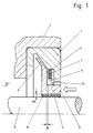
- the ferrofluid seal according to FIG. 1 consists of the outer ring 1 and the inner ring 2, which enclose one another in the radial direction.
- the inner ring 2 is provided with a flange projection 6 which is encompassed on both sides in the axial direction by the U-shaped profile of the outer ring 1 which is opened inwards.
- the flange projection 6 has a balanced distance in the axial direction on both sides from the respectively opposite boundary surfaces of the inwardly open groove of the outer ring 1.
- the bottom of the groove of the outer ring 1 has a radial distance from the outer diameter of the flange projection 6.
- the inner ring 2 and the outer ring 1 can both consist of magnetizable materials, for example steel. They have mutually opposite surfaces that together delimit a gap. This contains the ferrofluidic liquid. If the inner ring 2 is made of a magnetizable material and the outer ring 1 is made of a non-magnetic material, there is the advantage that magnetic field scattering can be avoided and the ferrofluidic liquid can be better assigned to a specific point in the gap.
- a ring magnet 4 is mounted relatively non-rotatably in the outer ring 1, its magnet facing the flange projection 6, which extends in the radial direction Boundary surface has the distance A from the flange projection 6.
- the gap 3 extending in the radial direction is limited on both sides in the axial direction. In the operational state of the seal shown, it is of a very small width of only 0.15 mm.
- annular pole shoe 10 Arranged in the axial direction between the ring magnet 4 and the inward-facing flange projection of the outer ring 1, which is in the same radial plane, is the annular pole shoe 10, which projects beyond the radially inward-facing boundary surface of the ring magnet 4 in the radial direction inwards and the inner ring 2 on the outside is relatively close. Radially within the gap 3, this results in an annular space 11 of comparatively enlarged cross section. Like the area between the pole piece 10 and the inner ring 2 and the gap 3, the latter is filled with ferrofluidic liquid, which forms a reserve volume for the area of the gap 3. The actual sealing takes place in this area.
- the inside diameter of the pole shoe 10 be assigned to the side of the inner ring 2 facing it in a particularly narrow manner. Only the leakage of the ferrofluidic liquid has to be prevented in this area.
- the space to be sealed is labeled D.
- an inner layer 8 made of rubber is ribbed. This assigns the radial layer thickness B.
- a similar layer is not provided between the outside of the outer ring 1 and the adjacent machine part 12. A liquid-tight interference fit must therefore be provided in this area between the outer ring 1 and the adjacent machine part 12 in order to ensure a liquid-tight mutual connection.
- the press-in process is continued until the opposing, radially directed end faces of the outer ring 1 and the machine part receiving it 12 touch each other. Thereafter, the press-in force previously exerted on the support surface 7 is withdrawn, which leads to the fact that the stresses present in the intermediate layer 8 equalize and cause a right-hand relative displacement of the inner ring 2 against the direction of the arrow 1 shown.
- the gap 3 thereby receives the necessary axial width A of 0.15 mm. This enables the built-in seal to be put into operation immediately.
- the ring-shaped projection 6 of the inner ring 2 acts as a slinger. It is arranged between the space D to be sealed and the gap 3, whereby the latter is protected from pressure fluctuations in the space D to be sealed. Even in such a case, there is no fear of a disadvantageous change in the sealing result achieved.
- the embodiment shown in Figure 2 consists of the outer ring 1 and the inner ring 2, which enclose each other in the radial direction and both consist of magnetizable materials. They are secured against axial and radial relative displacement with respect to each other during transport and assembly of the seal by three grub screws 5 distributed uniformly over the circumference.
- Both the outer ring 1 and the inner ring 2 are statically sealed from the adjacent machine parts 12 and 9 by O-ring seals 13. It requires therefore no high degree of mutual compression between the contacting surfaces of the seal and the machine parts to be sealed in order to achieve the required static sealing result in the areas mentioned.
- the installation of the seal by axially inserting it into the gap between the machine parts 9, 12 can accordingly take place while avoiding significant press-in forces.
- the grub screws 5 are then removed.
- the built-in seal is now functional.
- the outer ring 1 of the seal described above also contains an additional reservoir 16 for ferrofluidic liquid.
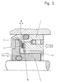
- the seal shown in Figure 3 is similar to that described above in terms of its design.
- the inner ring 2 is made of plastic, the surface being provided with a magnetizable coating made of steel, for example a sheet metal ring, in the area of those surfaces which lie opposite the ring magnet 4 and the annular pole piece 10.
- shear pins 5 are evenly distributed on the circumference on the inner ring 2. These are integrally formed and support the outer ring 1 on the inner ring 2 in the axial direction when the press-in forces required for the installation of the seal are applied via one of the areas indicated by an open arrow.
- the shear pins 5 are destroyed. They are then no longer able to hinder the relative rotation and their fragments leave the gap to be sealed due to centrifugal force.
- the inward-looking ring projection 11 of the outer ring forms a ballast seal, through which the penetration of coarse dirt from the environment into the annular gap is prevented.
- the seal according to the invention is a cassette seal, which can thus be assembled and put into operation without great expense.
- Their axial length is relatively small and radial relative displacements of the rotating shaft can easily be accepted.
Landscapes
- Engineering & Computer Science (AREA)
- General Engineering & Computer Science (AREA)
- Mechanical Engineering (AREA)
- Sealing Using Fluids, Sealing Without Contact, And Removal Of Oil (AREA)
- Centrifugal Separators (AREA)
- Joints Allowing Movement (AREA)
Claims (9)
- Joint à fluide magnétique, dans lequel les bagues d'étanchéité (1, 2) pouvant tourner l'une par rapport à l'autre délimitent un intervalle (3) entourant concentriquement l'axe de rotation d'un arbre (9), un fluide magnétique étant disposé dans cet intervalle et étant maintenu par le champ magnétique d'un aimant annulaire (4), caractérisé en ce que l'intervalle (3) contenant le fluide magnétique s'étend dans l'essentiel dans une direction radiale et fait avec l'axe de rotation un angle d'environ 90 degrés et en ce que l'intervalle (3) à l'endroit où l'intervalle (3) a son plus grand diamètre extérieur, est ouvert radialement vers l'extérieur et est délimité par des surfaces des bagues d'étanchéité (1, 2), qui sont espacées axialement l'une de l'autre d'une distance axiale (A) au maximum de 0,5 mm, de telle sorte que la force de maintien exercée par le champ magnétique sur le fluide magnétique se trouvant dans l'intervalle (3) dépasse d'au moins 20 fois la force centrifuge se produisant pendant l'utilisation conforme aux prescriptions.
- Joint selon la revendication 1, caractérisé en ce que l'espacement (A) a une largeur au maximum de 0,2 mm.
- Joint selon la revendication 1 ou 2, caractérisé en ce que la disposition mutuelle axiale des bagues d'étanchéité (1, 2) est déterminée dans une direction axiale par au moins un organe de maintien d'espacement (5) et en ce que la fonction de cet organe de maintien d'espacement (5) est supprimée avant la mise en service du joint.
- Joint selon la revendication 3, caractérisé en ce que l'organe de maintien d'espacement (5) se compose d'un élément de fixation maintenant axialement l'une contre l'autre les bagues d'étanchéité (1, 2).
- Joint selon la revendication 4, caractérisé en ce que l'élément de fixation a une forme annulaire.
- Joint selon la revendication 4 ou 5, caractérisé en ce que l'élément de fixation peut être enlevé.
- Joint selon une des revendications 4 à 6, caractérisé en ce que l'élément de fixation peut être détruit par une rotation relative des bagues d'étanchéité (1, 2).
- Joint selon une des revendications 1 ou 2, caractérisé en ce qu'une des bagues d'étanchéité (2) est pourvue d'un rebord annulaire radial (6) et est entourée axialement, dans une zone du rebord annulaire (6), par le profil en forme de U de l'autre bague (1), en ce qu'une des bagues d'étanchéité (2) est pourvue d'au moins une surface frontale d'appui (7) pour l'emmanchement du joint dans l'intervalle d'étanchéité prévu entre les pièces de machine à étancher et est appuyée par une couche intermédiaire (8) de caoutchouc contre la surface opposée, située en regard dans une direction radiale, de la pièce de machine (9) relativement non tournante, et en ce que l'épaisseur radiale (B) de la couche intermédiaire (8) est dimensionnée de telle sorte que la couche intermédiaire (8), reprenant élastiquement sa forme après terminaison de l'emmanchement, assure le réglage de l'espacement (A) entre les bagues d'étanchéité (1, 2).
- Joint selon la revendication 8, caractérisé en ce que le rebord annulaire (6) est interrompu dans une direction axiale en au moins un endroit de son pourtour.
Priority Applications (1)
| Application Number | Priority Date | Filing Date | Title |
|---|---|---|---|
| AT88121078T ATE87998T1 (de) | 1988-04-02 | 1988-12-16 | Ferrofluiddichtung. |
Applications Claiming Priority (2)
| Application Number | Priority Date | Filing Date | Title |
|---|---|---|---|
| DE3811227A DE3811227C2 (de) | 1988-04-02 | 1988-04-02 | Ferrofluiddichtung |
| DE3811227 | 1988-04-02 |
Publications (3)
| Publication Number | Publication Date |
|---|---|
| EP0336016A2 EP0336016A2 (fr) | 1989-10-11 |
| EP0336016A3 EP0336016A3 (fr) | 1991-01-23 |
| EP0336016B1 true EP0336016B1 (fr) | 1993-04-07 |
Family
ID=6351290
Family Applications (1)
| Application Number | Title | Priority Date | Filing Date |
|---|---|---|---|
| EP88121078A Expired - Lifetime EP0336016B1 (fr) | 1988-04-02 | 1988-12-16 | Joint à fluide magnétique |
Country Status (5)
| Country | Link |
|---|---|
| EP (1) | EP0336016B1 (fr) |
| JP (1) | JPH0733869B2 (fr) |
| AT (1) | ATE87998T1 (fr) |
| DE (2) | DE3811227C2 (fr) |
| ES (1) | ES2039581T3 (fr) |
Families Citing this family (4)
| Publication number | Priority date | Publication date | Assignee | Title |
|---|---|---|---|---|
| AU4863093A (en) * | 1992-10-08 | 1994-04-21 | Ferrofluidics Corporation | Ferrofluidic seal centering ring |
| CN101737497B (zh) * | 2010-02-11 | 2011-08-03 | 北京交通大学 | 一种磁性液体与三斜口填料环组合式往复轴密封装置 |
| JP5871374B2 (ja) * | 2012-01-12 | 2016-03-01 | 株式会社リガク | 磁性流体シール装置 |
| CN112747037B (zh) * | 2019-10-31 | 2023-04-07 | 新疆金风科技股份有限公司 | 轴系结构、密封组件以及风力发电机组 |
Citations (1)
| Publication number | Priority date | Publication date | Assignee | Title |
|---|---|---|---|---|
| DE2034213A1 (de) * | 1969-10-10 | 1971-05-06 | Ferrofluidics Corp | Magnetische Flüssigkeitsdichtung |
Family Cites Families (12)
| Publication number | Priority date | Publication date | Assignee | Title |
|---|---|---|---|---|
| DE637097C (de) * | 1935-05-22 | 1936-10-21 | Hermann Mecke | Abdichtung fuer Lager |
| US3341264A (en) * | 1965-09-03 | 1967-09-12 | Timken Roller Bearing Co | Unitized dual lip seal |
| JPS4885950A (fr) * | 1972-02-18 | 1973-11-14 | ||
| JPS53110761A (en) * | 1977-03-09 | 1978-09-27 | Akira Washida | Shaft seal |
| JPS53148656A (en) * | 1977-05-31 | 1978-12-25 | Akira Washida | Shaft seal |
| US4357024A (en) * | 1980-11-19 | 1982-11-02 | Ferrofluidics Corporation | Ferrofluid rotary-shaft seal apparatus and method |
| US4486026A (en) * | 1982-02-10 | 1984-12-04 | Nippon Seiko K.K. | Sealing and bearing means by use of ferrofluid |
| DE3204989C2 (de) * | 1982-02-12 | 1983-12-15 | Fa. Carl Freudenberg, 6940 Weinheim | Kassettendichtung |
| DE3213809C2 (de) * | 1982-04-15 | 1984-06-20 | Fa. Carl Freudenberg, 6940 Weinheim | Kassettendichtung |
| US4478424A (en) * | 1984-01-27 | 1984-10-23 | Ferrofluidics Corporation | Ferrofluid seal apparatus and method |
| US4671679A (en) * | 1986-05-05 | 1987-06-09 | Mechanical Technology Incorporated | Magnetic fluid devices such as magnetic fluid bearings, seals, and the like and an automatic magnetic fluid supply control system therefor |
| US4694213A (en) * | 1986-11-21 | 1987-09-15 | Ferrofluidics Corporation | Ferrofluid seal for a stationary shaft and a rotating hub |
-
1988
- 1988-04-02 DE DE3811227A patent/DE3811227C2/de not_active Expired - Lifetime
- 1988-12-16 ES ES198888121078T patent/ES2039581T3/es not_active Expired - Lifetime
- 1988-12-16 DE DE8888121078T patent/DE3880127D1/de not_active Expired - Lifetime
- 1988-12-16 EP EP88121078A patent/EP0336016B1/fr not_active Expired - Lifetime
- 1988-12-16 AT AT88121078T patent/ATE87998T1/de active
-
1989
- 1989-03-20 JP JP1069107A patent/JPH0733869B2/ja not_active Expired - Lifetime
Patent Citations (1)
| Publication number | Priority date | Publication date | Assignee | Title |
|---|---|---|---|---|
| DE2034213A1 (de) * | 1969-10-10 | 1971-05-06 | Ferrofluidics Corp | Magnetische Flüssigkeitsdichtung |
Also Published As
| Publication number | Publication date |
|---|---|
| EP0336016A3 (fr) | 1991-01-23 |
| JPH0733869B2 (ja) | 1995-04-12 |
| DE3811227C2 (de) | 1996-04-11 |
| DE3811227A1 (de) | 1989-10-12 |
| EP0336016A2 (fr) | 1989-10-11 |
| JPH01279171A (ja) | 1989-11-09 |
| ATE87998T1 (de) | 1993-04-15 |
| DE3880127D1 (en) | 1993-05-13 |
| ES2039581T3 (es) | 1993-10-01 |
Similar Documents
| Publication | Publication Date | Title |
|---|---|---|
| DE3824586B4 (de) | Verbund-Dichtung | |
| DE3412484C2 (de) | Öldichtungsanordnung | |
| EP1563209B1 (fr) | Element d'etancheite secondaire | |
| DE69819602T2 (de) | Radialwellendichtung | |
| DE3530582A1 (de) | Ferrofluid-dichtungsanordnung, ferrofluid-dichtungssystem und verfahren zur herstellung einer ferrofluid-dichtungsanordnung | |
| DE69427646T2 (de) | Dichtung für eine vorrichtung zum filtrieren von polymeren | |
| DE60211454T2 (de) | Gleitringdichtungsanordnung | |
| DE69000421T2 (de) | Montagevorrichtung fuer ein lager auf einer welle. | |
| EP0248944B1 (fr) | Soupape d'arrêt | |
| EP0336016B1 (fr) | Joint à fluide magnétique | |
| EP0328737B1 (fr) | Joint d'étanchéité | |
| EP4179226B1 (fr) | Amortisseur de vibrations de torsion | |
| EP0005159B1 (fr) | Joint d'étanchéité par bague glissante | |
| EP0052689A1 (fr) | Joint d'étanchéité pour tiges ou pistons | |
| DE10140837C1 (de) | Dichtungsanordnung | |
| DE3214589C2 (fr) | ||
| DE3876343T2 (de) | Magnetische dichtungseinrichtung. | |
| EP0946837B1 (fr) | Garniture d'etancheite | |
| DE2546805B2 (de) | Dichtring für drehbare Körper, wie Wellen o.dgl | |
| DE69208034T2 (de) | Abdichtung | |
| DE3607736C2 (de) | Absperrklappe | |
| EP0085934B1 (fr) | Accumulateur de pression | |
| DE2740219C2 (de) | Gleitringdichtung | |
| DE19821669C1 (de) | Gleitringdichtung | |
| DE19846124C1 (de) | Gleitringdichtung |
Legal Events
| Date | Code | Title | Description |
|---|---|---|---|
| PUAI | Public reference made under article 153(3) epc to a published international application that has entered the european phase |
Free format text: ORIGINAL CODE: 0009012 |
|
| AK | Designated contracting states |
Kind code of ref document: A2 Designated state(s): AT BE CH DE ES FR GB IT LI NL SE |
|
| PUAL | Search report despatched |
Free format text: ORIGINAL CODE: 0009013 |
|
| AK | Designated contracting states |
Kind code of ref document: A3 Designated state(s): AT BE CH DE ES FR GB IT LI NL SE |
|
| 17P | Request for examination filed |
Effective date: 19901214 |
|
| 17Q | First examination report despatched |
Effective date: 19920922 |
|
| ITF | It: translation for a ep patent filed | ||
| GRAA | (expected) grant |
Free format text: ORIGINAL CODE: 0009210 |
|
| AK | Designated contracting states |
Kind code of ref document: B1 Designated state(s): AT BE CH DE ES FR GB IT LI NL SE |
|
| REF | Corresponds to: |
Ref document number: 87998 Country of ref document: AT Date of ref document: 19930415 Kind code of ref document: T |
|
| ET | Fr: translation filed | ||
| REF | Corresponds to: |
Ref document number: 3880127 Country of ref document: DE Date of ref document: 19930513 |
|
| GBT | Gb: translation of ep patent filed (gb section 77(6)(a)/1977) |
Effective date: 19930422 |
|
| REG | Reference to a national code |
Ref country code: ES Ref legal event code: FG2A Ref document number: 2039581 Country of ref document: ES Kind code of ref document: T3 |
|
| ITTA | It: last paid annual fee | ||
| PLBE | No opposition filed within time limit |
Free format text: ORIGINAL CODE: 0009261 |
|
| STAA | Information on the status of an ep patent application or granted ep patent |
Free format text: STATUS: NO OPPOSITION FILED WITHIN TIME LIMIT |
|
| 26N | No opposition filed | ||
| EAL | Se: european patent in force in sweden |
Ref document number: 88121078.5 |
|
| PGFP | Annual fee paid to national office [announced via postgrant information from national office to epo] |
Ref country code: SE Payment date: 19951122 Year of fee payment: 8 |
|
| PGFP | Annual fee paid to national office [announced via postgrant information from national office to epo] |
Ref country code: GB Payment date: 19951128 Year of fee payment: 8 |
|
| PGFP | Annual fee paid to national office [announced via postgrant information from national office to epo] |
Ref country code: BE Payment date: 19951211 Year of fee payment: 8 |
|
| PGFP | Annual fee paid to national office [announced via postgrant information from national office to epo] |
Ref country code: CH Payment date: 19951212 Year of fee payment: 8 Ref country code: AT Payment date: 19951212 Year of fee payment: 8 |
|
| PGFP | Annual fee paid to national office [announced via postgrant information from national office to epo] |
Ref country code: FR Payment date: 19951214 Year of fee payment: 8 |
|
| PGFP | Annual fee paid to national office [announced via postgrant information from national office to epo] |
Ref country code: ES Payment date: 19951215 Year of fee payment: 8 |
|
| PGFP | Annual fee paid to national office [announced via postgrant information from national office to epo] |
Ref country code: DE Payment date: 19951220 Year of fee payment: 8 |
|
| PGFP | Annual fee paid to national office [announced via postgrant information from national office to epo] |
Ref country code: NL Payment date: 19951230 Year of fee payment: 8 |
|
| PG25 | Lapsed in a contracting state [announced via postgrant information from national office to epo] |
Ref country code: DE Effective date: 19960508 |
|
| PG25 | Lapsed in a contracting state [announced via postgrant information from national office to epo] |
Ref country code: GB Effective date: 19961216 Ref country code: AT Effective date: 19961216 |
|
| PG25 | Lapsed in a contracting state [announced via postgrant information from national office to epo] |
Ref country code: SE Effective date: 19961217 Ref country code: ES Free format text: LAPSE BECAUSE OF EXPIRATION OF PROTECTION Effective date: 19961217 |
|
| PG25 | Lapsed in a contracting state [announced via postgrant information from national office to epo] |
Ref country code: LI Effective date: 19961231 Ref country code: CH Effective date: 19961231 Ref country code: BE Effective date: 19961231 |
|
| BERE | Be: lapsed |
Owner name: FIRMA CARL FREUDENBERG Effective date: 19961231 |
|
| PG25 | Lapsed in a contracting state [announced via postgrant information from national office to epo] |
Ref country code: NL Effective date: 19970701 |
|
| GBPC | Gb: european patent ceased through non-payment of renewal fee |
Effective date: 19961216 |
|
| REG | Reference to a national code |
Ref country code: CH Ref legal event code: PL |
|
| PG25 | Lapsed in a contracting state [announced via postgrant information from national office to epo] |
Ref country code: FR Effective date: 19970829 |
|
| NLV4 | Nl: lapsed or anulled due to non-payment of the annual fee |
Effective date: 19970701 |
|
| EUG | Se: european patent has lapsed |
Ref document number: 88121078.5 |
|
| REG | Reference to a national code |
Ref country code: FR Ref legal event code: ST |
|
| REG | Reference to a national code |
Ref country code: ES Ref legal event code: FD2A Effective date: 20010301 |
|
| PG25 | Lapsed in a contracting state [announced via postgrant information from national office to epo] |
Ref country code: IT Free format text: LAPSE BECAUSE OF NON-PAYMENT OF DUE FEES Effective date: 20051216 |