EP0336025A1 - Zeitbereichsreflektometriemessverfahren sowie Anordnung zu dessen Durchführung - Google Patents
Zeitbereichsreflektometriemessverfahren sowie Anordnung zu dessen Durchführung Download PDFInfo
- Publication number
- EP0336025A1 EP0336025A1 EP88302996A EP88302996A EP0336025A1 EP 0336025 A1 EP0336025 A1 EP 0336025A1 EP 88302996 A EP88302996 A EP 88302996A EP 88302996 A EP88302996 A EP 88302996A EP 0336025 A1 EP0336025 A1 EP 0336025A1
- Authority
- EP
- European Patent Office
- Prior art keywords
- target
- transmission line
- signal
- measurement
- line
- Prior art date
- Legal status (The legal status is an assumption and is not a legal conclusion. Google has not performed a legal analysis and makes no representation as to the accuracy of the status listed.)
- Granted
Links
- 238000000691 measurement method Methods 0.000 title description 2
- 230000005540 biological transmission Effects 0.000 claims abstract description 38
- 238000005259 measurement Methods 0.000 claims abstract description 37
- 238000012545 processing Methods 0.000 claims abstract description 17
- 238000000034 method Methods 0.000 claims abstract description 11
- 229910001218 Gallium arsenide Inorganic materials 0.000 claims description 5
- 239000002184 metal Substances 0.000 claims description 4
- 239000003989 dielectric material Substances 0.000 claims description 2
- 230000010354 integration Effects 0.000 description 7
- 238000004519 manufacturing process Methods 0.000 description 4
- 238000010586 diagram Methods 0.000 description 2
- 238000002310 reflectometry Methods 0.000 description 2
- 230000008878 coupling Effects 0.000 description 1
- 238000010168 coupling process Methods 0.000 description 1
- 238000005859 coupling reaction Methods 0.000 description 1
- 239000013078 crystal Substances 0.000 description 1
- 230000001934 delay Effects 0.000 description 1
- 239000000284 extract Substances 0.000 description 1
- 238000012986 modification Methods 0.000 description 1
- 230000004048 modification Effects 0.000 description 1
- 230000001960 triggered effect Effects 0.000 description 1
Images


Classifications
-
- G—PHYSICS
- G01—MEASURING; TESTING
- G01B—MEASURING LENGTH, THICKNESS OR SIMILAR LINEAR DIMENSIONS; MEASURING ANGLES; MEASURING AREAS; MEASURING IRREGULARITIES OF SURFACES OR CONTOURS
- G01B7/00—Measuring arrangements characterised by the use of electric or magnetic techniques
- G01B7/02—Measuring arrangements characterised by the use of electric or magnetic techniques for measuring length, width or thickness
Definitions
- This invention relates to a measurement method and to measurement apparatus using time domain reflectometry (TDR).
- TDR time domain reflectometry
- time domain reflectometry is widely established as a means of identifying the presence of faults within electromagnetic cables and transmission lines, and of locating their position. Any fault will modify the characteristic impedance of the transmission line to incident electromagnetic waves which will hence be partially reflected. The reflected wave can be detected at the input end of the cable and the location of the fault determined from the time at which the reflection arrives.
- a method of precision length or position measurement which comprises:- a) extending a transmission line in a predetermined spatial orientation with respect to an object on which a length or position measurement is required; b) moving along the transmission line a target adapted by its proximity to the line to alter the impedance of the line at the position along the line at which the target is located; c) directing an electromagnetic signal into an input end of the line and measuring the time at which an electromagnetic signal is returned to the input end due to partial reflection of the input signal at the location of the target; and d) processing the returned signal to evaluate the position of the target along the line, thereby precisely to determine a length or position measurement on the object.
- the transmission line may extend parallel with the object (for precision length measurement), or the transmission line could adopt any other predetermined shape, such as an arc of a circle, in which case the predetermined shape and the position of the target will enable an accurate position measurement (such as an angular measurement) to be obtained.
- the method in accordance with the invention may be a method employed simply for precision length determination, the result being displayed, or the method may be extended, by feeding the output of the processing means to a suitable controller, to include the step of carrying out a manufacturing step, e.g. cutting, on the object, at a position thereon determined by the precision length measurement.
- a manufacturing step e.g. cutting
- movement of the target along the transmission line is arranged to be representative of the movement of the processing tool relative to the work piece.
- this may be effected with the target stationary at a position to which it has been moved, whilst in the case of a manufacturing method, one or more processing means may operate at a selected measured position or successive measured positions along the object, as the target is moved along the transmission line.
- a fast acting processing means is necessary substantially instantaneously to give a length determination corresponding to the instantaneous position of the target, and further features of the present invention, detailed hereinafter, make this possible.
- measurement apparatus comprising: - a transmission line adapted to propagate electromagnetic energy whose characteristic impedance is altered by the proximity of a target which is movable along the transmission line; - a signal source which generates a fast-rising, short pulse which is directed into an input end of the transmission line and is partially reflected at the target; and - means for processing the reflected signal to evaluate the position of the target.
- an open electromagnetic transmission line can be designed so that the presence of objects in its vicinity will similarly modify the characteristic impedance and thus cause a detectable reflection.
- This property has then been utilised by designing a target which can move along the transmission line.
- the transmission line is itself of such a characteristic impedance that there is preferably a reflection at the input of the transmission line and a reflection from the movable target, and the time difference between these two events is the basis of the precision length measurement.
- Traditional laboratory time domain reflectometers utilise a fast-rising step input signal with a rise time of less than around 100 ps and sample the reflected waveform at a sequence of delays, thus requiring many pulses to derive one measurement.
- a different method of processing the reflected waveform is utilised, which does not use a sampler, but extracts a time delay measurement by integration during the period of one or a series of pulses.
- the processing means comprises a flip-flop circuit such as a GaAs high speed flip-flop, which is triggered on and off by respective reflected pulses and causes a precision current source to be turned on and off.
- the instant length measurement is then indicated by the charge delivered by the current source to an integration circuit following one or multiple signal pulses.
- This preferred apparatus can provide substantially instantaneous measurement corresponding to the instantaneous position of the target.
- the preferred means for processing the TDR output can be designed with the advantage of producing a length measurement from a single pulse. This means that precision length measurement of a relatively fast moving target is available in a fraction of a millisecond.
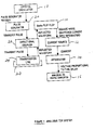
- the position of a target 28 along a transmission line 24 is measured by using the reflection from the input end of the transmission line to flip a GaAs flip-flop 10.
- the reflection from the target 28 then switches the GaAs flip-flop 10 back to its original level.
- the output from the flip-flop is used to switch a stable current source 12 into an integrator 14 which measures the duty cycle of the current which is proportional to the length of the 'ON' pulse and therefore to the position of the target.
- the voltage output of the integrator proportional to the time delay is fed to an A/D converter 16.
- the output from the analogue-to-digital converter 16 may either be passed to a display in a measurement application or to a controller in a manufacturing process.
- Figure 1 also shows a signal generator, which comprises a crystal oscillator 18 and a pulse geneerator 20, together with a directional coupler 22 through which the pulse input is fed into the input end of the transmission line 24.
- a signal generator which comprises a crystal oscillator 18 and a pulse geneerator 20, together with a directional coupler 22 through which the pulse input is fed into the input end of the transmission line 24.
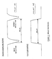
- a waveform in the form of a short voltage pulse ( Figure 3) is applied to the input end of the transmission line 24 via the directional coupling network 22.
- the transmission line is of a different impedance to the coupler output and there is thus a reflection due to this impedance discontinuity.
- the transmission line is then uniform except at the point where the target is located. There is then a reflection at the target, resulting in a complete reflected waveform of the form shown in Figure 4A.
- the reflected waveform ( Figure 4A) is used to switch the GaAs flip-flop 10 between its two states and gives rise to the output rectangular wave ( Figure 4B). This waveform is then used to switch a stable current from source 12 into the integration circuit 14, which measures the duty cycle of the flip-flop output.
- the time constant of the integration circuit is chosen according to the measurement accuracy required. For instance, if the reflected waveform has root mean square jitter of 10 picoseconds and a timing accuracy of 1 picosecond is required, then the integration circuit must integrate over 100 pulses.
- the output voltage (see Figure 5) from the integration circuit 14 is passed to the analogue-to-digital converter 16 whose reference is derived from the stable current source 12.
- FIG. 2A Two embodiments of the transmission line are shown in Figure 2.
- a metal or dielectric cursor 30 is suspended between an air spaced parallel plate transmission line 32.
- a metal or dielectric cursor 34 rides as a saddle along a transmission line 36 which comprises 2 parallel metal plates separated by an insulating layer of dielectric material.
Landscapes
- Physics & Mathematics (AREA)
- General Physics & Mathematics (AREA)
- Length-Measuring Devices Using Wave Or Particle Radiation (AREA)
- Measurement Of Length, Angles, Or The Like Using Electric Or Magnetic Means (AREA)
- Length Measuring Devices With Unspecified Measuring Means (AREA)
- Control Of Stepping Motors (AREA)
- Heat Treatment Of Sheet Steel (AREA)
- Credit Cards Or The Like (AREA)
- Locating Faults (AREA)
- Length Measuring Devices By Optical Means (AREA)
Priority Applications (4)
| Application Number | Priority Date | Filing Date | Title |
|---|---|---|---|
| AT88302996T ATE83067T1 (de) | 1988-04-05 | 1988-04-05 | Zeitbereichsreflektometriemessverfahren sowie anordnung zu dessen durchfuehrung. |
| DE8888302996T DE3876420T2 (de) | 1988-04-05 | 1988-04-05 | Zeitbereichsreflektometriemessverfahren sowie anordnung zu dessen durchfuehrung. |
| EP88302996A EP0336025B1 (de) | 1988-04-05 | 1988-04-05 | Zeitbereichsreflektometriemessverfahren sowie Anordnung zu dessen Durchführung |
| ES198888302996T ES2035916T3 (es) | 1988-04-05 | 1988-04-05 | Metodo y aparato de medicion que utilizan reflectometria de dominio temperal. |
Applications Claiming Priority (1)
| Application Number | Priority Date | Filing Date | Title |
|---|---|---|---|
| EP88302996A EP0336025B1 (de) | 1988-04-05 | 1988-04-05 | Zeitbereichsreflektometriemessverfahren sowie Anordnung zu dessen Durchführung |
Publications (2)
| Publication Number | Publication Date |
|---|---|
| EP0336025A1 true EP0336025A1 (de) | 1989-10-11 |
| EP0336025B1 EP0336025B1 (de) | 1992-12-02 |
Family
ID=8200016
Family Applications (1)
| Application Number | Title | Priority Date | Filing Date |
|---|---|---|---|
| EP88302996A Expired EP0336025B1 (de) | 1988-04-05 | 1988-04-05 | Zeitbereichsreflektometriemessverfahren sowie Anordnung zu dessen Durchführung |
Country Status (4)
| Country | Link |
|---|---|
| EP (1) | EP0336025B1 (de) |
| AT (1) | ATE83067T1 (de) |
| DE (1) | DE3876420T2 (de) |
| ES (1) | ES2035916T3 (de) |
Cited By (6)
| Publication number | Priority date | Publication date | Assignee | Title |
|---|---|---|---|---|
| US5734346A (en) * | 1992-05-23 | 1998-03-31 | Cambridge Consultants Limited | Method of an apparatus for detecting the displacement of a target |
| EP0851215A1 (de) * | 1996-12-26 | 1998-07-01 | Nikon Corporation | Winkelmessvorrichtung |
| EP1595157A1 (de) * | 2003-02-20 | 2005-11-16 | Raytheon Company | Verfahren und system zum anpassen der elektrischen länge |
| GB2435358A (en) * | 2006-02-15 | 2007-08-22 | Schlumberger Holdings | Determining a well depth by measuring a length of an electrical cable |
| AT508294B1 (de) * | 2009-06-08 | 2012-04-15 | Advanced Drilling Solutions Gmbh | Vorrichtung zum erfassen der länge eines bohrgestänges |
| DE112007003213B4 (de) * | 2007-07-23 | 2018-02-15 | TRUMPF Hüttinger GmbH + Co. KG | Verfahren zur Ermittlung der Wellenlaufzeit zwischen zumindest einem Inverter in einer Plasmaleistungsversorgungseinrichtung und einer an diese angeschlossenen Last und Plasmaleistungsversorgungseinrichtung |
Families Citing this family (1)
| Publication number | Priority date | Publication date | Assignee | Title |
|---|---|---|---|---|
| US12474472B2 (en) | 2023-08-28 | 2025-11-18 | B/E Aerospace, Inc. | Electromagnetic transmission line sensors |
Citations (3)
| Publication number | Priority date | Publication date | Assignee | Title |
|---|---|---|---|---|
| US3898555A (en) * | 1973-12-19 | 1975-08-05 | Tempo Instr Inc | Linear distance measuring device using a moveable magnet interacting with a sonic waveguide |
| US4135397A (en) * | 1977-06-03 | 1979-01-23 | Krake Guss L | Level measuring system |
| EP0229505A1 (de) * | 1985-12-16 | 1987-07-22 | Fujitsu Limited | Verfahren zur Messung der Zeitverzögerung eines Kabels |
-
1988
- 1988-04-05 ES ES198888302996T patent/ES2035916T3/es not_active Expired - Lifetime
- 1988-04-05 AT AT88302996T patent/ATE83067T1/de not_active IP Right Cessation
- 1988-04-05 EP EP88302996A patent/EP0336025B1/de not_active Expired
- 1988-04-05 DE DE8888302996T patent/DE3876420T2/de not_active Expired - Fee Related
Patent Citations (3)
| Publication number | Priority date | Publication date | Assignee | Title |
|---|---|---|---|---|
| US3898555A (en) * | 1973-12-19 | 1975-08-05 | Tempo Instr Inc | Linear distance measuring device using a moveable magnet interacting with a sonic waveguide |
| US4135397A (en) * | 1977-06-03 | 1979-01-23 | Krake Guss L | Level measuring system |
| EP0229505A1 (de) * | 1985-12-16 | 1987-07-22 | Fujitsu Limited | Verfahren zur Messung der Zeitverzögerung eines Kabels |
Non-Patent Citations (1)
| Title |
|---|
| WIRELESS WORLD, vol. 89, no. 1571, August 1983, page 39, Olchester, GB; A. SUTER: "Direct reading cable reflectometer" * |
Cited By (9)
| Publication number | Priority date | Publication date | Assignee | Title |
|---|---|---|---|---|
| US5734346A (en) * | 1992-05-23 | 1998-03-31 | Cambridge Consultants Limited | Method of an apparatus for detecting the displacement of a target |
| EP0851215A1 (de) * | 1996-12-26 | 1998-07-01 | Nikon Corporation | Winkelmessvorrichtung |
| EP1595157A1 (de) * | 2003-02-20 | 2005-11-16 | Raytheon Company | Verfahren und system zum anpassen der elektrischen länge |
| CN100442075C (zh) * | 2003-02-20 | 2008-12-10 | 雷西昂公司 | 电长度匹配的方法和系统 |
| GB2435358A (en) * | 2006-02-15 | 2007-08-22 | Schlumberger Holdings | Determining a well depth by measuring a length of an electrical cable |
| GB2435358B (en) * | 2006-02-15 | 2009-02-18 | Schlumberger Holdings | Well depth measurement |
| US8269647B2 (en) | 2006-02-15 | 2012-09-18 | Schlumberger Technology Corporation | Well depth measurement using time domain reflectometry |
| DE112007003213B4 (de) * | 2007-07-23 | 2018-02-15 | TRUMPF Hüttinger GmbH + Co. KG | Verfahren zur Ermittlung der Wellenlaufzeit zwischen zumindest einem Inverter in einer Plasmaleistungsversorgungseinrichtung und einer an diese angeschlossenen Last und Plasmaleistungsversorgungseinrichtung |
| AT508294B1 (de) * | 2009-06-08 | 2012-04-15 | Advanced Drilling Solutions Gmbh | Vorrichtung zum erfassen der länge eines bohrgestänges |
Also Published As
| Publication number | Publication date |
|---|---|
| DE3876420D1 (de) | 1993-01-14 |
| EP0336025B1 (de) | 1992-12-02 |
| ATE83067T1 (de) | 1992-12-15 |
| ES2035916T3 (es) | 1993-05-01 |
| DE3876420T2 (de) | 1993-04-08 |
Similar Documents
| Publication | Publication Date | Title |
|---|---|---|
| US6801157B2 (en) | Guided wave radar level transmitter | |
| US3995212A (en) | Apparatus and method for sensing a liquid with a single wire transmission line | |
| US7823446B2 (en) | Pulsed radar level gauging with relative phase detection | |
| US4196406A (en) | Ultrasonic control device | |
| CN113544531B (zh) | 用于测试利用电磁波工作的距离传感器的测试设备 | |
| GB2283632A (en) | Device for testing an electrical line | |
| EP0182834A1 (de) | Optoelektrisches entfernungsmessgerät mit einem zeitdiskriminator zur genauen ermittlung der zeitfolge elektrischer impulse | |
| EP0336025A1 (de) | Zeitbereichsreflektometriemessverfahren sowie Anordnung zu dessen Durchführung | |
| Hugenholtz et al. | Pulse radar technique for reflectometry on thermonuclear plasmas | |
| GB2055269A (en) | Checking the location of moving parts in a machine | |
| JPS5737257A (en) | Bonding inspection apparatus | |
| US2862200A (en) | Measuring apparatus | |
| JP3198904B2 (ja) | 導電体長計測装置及びレベル計測装置 | |
| JPS639182B2 (de) | ||
| RU2150747C1 (ru) | Устройство для счета штучных изделий, перемещающихся по конвейеру | |
| EP0018079A1 (de) | Digitales Ultraschall-Holographiegerät | |
| JPH0210277A (ja) | 回路試験方法及びその装置 | |
| EP0324855A1 (de) | Verfahren und gerät zur feststellung von rissen mittels ultraschall | |
| Ross | Early developments and motivations for time-domain analysis and application | |
| KR100542866B1 (ko) | 저속 클럭 발생기와 저속 에이디 컨버터를 이용한 시간영역 반사 측정 장치 | |
| JPH04132931A (ja) | 光ファイバ障害点位置検査機 | |
| RU2042194C1 (ru) | Устройство для моделирования радиотехнической системы передачи информации с амплитудно-импульсной модуляцией | |
| Opalska et al. | A pulser with inverted microstrip line for time-domain reflectometry | |
| SU1226360A1 (ru) | Устройство дл определени рассто ни до места повреждени изол ции жилы на оболочку силового кабел | |
| SU845004A2 (ru) | Преобразователь распределени интен-СиВНОСТи CBETA BO ВРЕМЕННую пОСлЕдО-ВАТЕльНОСТь элЕКТРичЕСКиХ СигНАлОВ |
Legal Events
| Date | Code | Title | Description |
|---|---|---|---|
| PUAI | Public reference made under article 153(3) epc to a published international application that has entered the european phase |
Free format text: ORIGINAL CODE: 0009012 |
|
| AK | Designated contracting states |
Kind code of ref document: A1 Designated state(s): AT CH DE ES FR GB IT LI NL SE |
|
| 17P | Request for examination filed |
Effective date: 19891107 |
|
| RAP3 | Party data changed (applicant data changed or rights of an application transferred) |
Owner name: DR. JOHANNES HEIDENHAIN GMBH |
|
| 17Q | First examination report despatched |
Effective date: 19910614 |
|
| ITF | It: translation for a ep patent filed | ||
| GRAA | (expected) grant |
Free format text: ORIGINAL CODE: 0009210 |
|
| AK | Designated contracting states |
Kind code of ref document: B1 Designated state(s): AT CH DE ES FR GB IT LI NL SE |
|
| REF | Corresponds to: |
Ref document number: 83067 Country of ref document: AT Date of ref document: 19921215 Kind code of ref document: T |
|
| ET | Fr: translation filed | ||
| REF | Corresponds to: |
Ref document number: 3876420 Country of ref document: DE Date of ref document: 19930114 |
|
| PG25 | Lapsed in a contracting state [announced via postgrant information from national office to epo] |
Ref country code: AT Effective date: 19930405 |
|
| PG25 | Lapsed in a contracting state [announced via postgrant information from national office to epo] |
Ref country code: SE Effective date: 19930406 Ref country code: ES Free format text: LAPSE BECAUSE OF EXPIRATION OF PROTECTION Effective date: 19930406 |
|
| PG25 | Lapsed in a contracting state [announced via postgrant information from national office to epo] |
Ref country code: LI Effective date: 19930430 Ref country code: CH Effective date: 19930430 |
|
| REG | Reference to a national code |
Ref country code: ES Ref legal event code: FG2A Ref document number: 2035916 Country of ref document: ES Kind code of ref document: T3 |
|
| PLBE | No opposition filed within time limit |
Free format text: ORIGINAL CODE: 0009261 |
|
| STAA | Information on the status of an ep patent application or granted ep patent |
Free format text: STATUS: NO OPPOSITION FILED WITHIN TIME LIMIT |
|
| PG25 | Lapsed in a contracting state [announced via postgrant information from national office to epo] |
Ref country code: NL Effective date: 19931101 |
|
| 26N | No opposition filed | ||
| NLV4 | Nl: lapsed or anulled due to non-payment of the annual fee | ||
| REG | Reference to a national code |
Ref country code: CH Ref legal event code: PL |
|
| EUG | Se: european patent has lapsed |
Ref document number: 88302996.9 Effective date: 19931110 |
|
| REG | Reference to a national code |
Ref country code: ES Ref legal event code: FD2A Effective date: 19991201 |
|
| PGFP | Annual fee paid to national office [announced via postgrant information from national office to epo] |
Ref country code: GB Payment date: 20010316 Year of fee payment: 14 |
|
| PGFP | Annual fee paid to national office [announced via postgrant information from national office to epo] |
Ref country code: FR Payment date: 20010410 Year of fee payment: 14 |
|
| REG | Reference to a national code |
Ref country code: GB Ref legal event code: IF02 |
|
| PG25 | Lapsed in a contracting state [announced via postgrant information from national office to epo] |
Ref country code: GB Free format text: LAPSE BECAUSE OF NON-PAYMENT OF DUE FEES Effective date: 20020405 |
|
| PGFP | Annual fee paid to national office [announced via postgrant information from national office to epo] |
Ref country code: DE Payment date: 20020418 Year of fee payment: 15 |
|
| GBPC | Gb: european patent ceased through non-payment of renewal fee |
Effective date: 20020405 |
|
| PG25 | Lapsed in a contracting state [announced via postgrant information from national office to epo] |
Ref country code: FR Free format text: LAPSE BECAUSE OF NON-PAYMENT OF DUE FEES Effective date: 20021231 |
|
| REG | Reference to a national code |
Ref country code: FR Ref legal event code: ST |
|
| PG25 | Lapsed in a contracting state [announced via postgrant information from national office to epo] |
Ref country code: DE Free format text: LAPSE BECAUSE OF NON-PAYMENT OF DUE FEES Effective date: 20031101 |
|
| PG25 | Lapsed in a contracting state [announced via postgrant information from national office to epo] |
Ref country code: IT Free format text: LAPSE BECAUSE OF NON-PAYMENT OF DUE FEES Effective date: 20050405 |