EP0336076A2 - Méthode de réglage de la diffèrence de la température d'enclenchement et de déclenchement d'un aggrégat de refroidissement - Google Patents
Méthode de réglage de la diffèrence de la température d'enclenchement et de déclenchement d'un aggrégat de refroidissement Download PDFInfo
- Publication number
- EP0336076A2 EP0336076A2 EP89102436A EP89102436A EP0336076A2 EP 0336076 A2 EP0336076 A2 EP 0336076A2 EP 89102436 A EP89102436 A EP 89102436A EP 89102436 A EP89102436 A EP 89102436A EP 0336076 A2 EP0336076 A2 EP 0336076A2
- Authority
- EP
- European Patent Office
- Prior art keywords
- temperature
- switch
- setpoint
- unit
- temperatures
- Prior art date
- Legal status (The legal status is an assumption and is not a legal conclusion. Google has not performed a legal analysis and makes no representation as to the accuracy of the status listed.)
- Granted
Links
Images
Classifications
-
- F—MECHANICAL ENGINEERING; LIGHTING; HEATING; WEAPONS; BLASTING
- F25—REFRIGERATION OR COOLING; COMBINED HEATING AND REFRIGERATION SYSTEMS; HEAT PUMP SYSTEMS; MANUFACTURE OR STORAGE OF ICE; LIQUEFACTION SOLIDIFICATION OF GASES
- F25D—REFRIGERATORS; COLD ROOMS; ICE-BOXES; COOLING OR FREEZING APPARATUS NOT OTHERWISE PROVIDED FOR
- F25D29/00—Arrangement or mounting of control or safety devices
-
- G—PHYSICS
- G05—CONTROLLING; REGULATING
- G05D—SYSTEMS FOR CONTROLLING OR REGULATING NON-ELECTRIC VARIABLES
- G05D23/00—Control of temperature
- G05D23/19—Control of temperature characterised by the use of electric means
- G05D23/1906—Control of temperature characterised by the use of electric means using an analogue comparing device
- G05D23/1909—Control of temperature characterised by the use of electric means using an analogue comparing device whose output amplitude can only take two discrete values
-
- G—PHYSICS
- G05—CONTROLLING; REGULATING
- G05D—SYSTEMS FOR CONTROLLING OR REGULATING NON-ELECTRIC VARIABLES
- G05D23/00—Control of temperature
- G05D23/19—Control of temperature characterised by the use of electric means
- G05D23/20—Control of temperature characterised by the use of electric means with sensing elements having variation of electric or magnetic properties with change of temperature
-
- F—MECHANICAL ENGINEERING; LIGHTING; HEATING; WEAPONS; BLASTING
- F25—REFRIGERATION OR COOLING; COMBINED HEATING AND REFRIGERATION SYSTEMS; HEAT PUMP SYSTEMS; MANUFACTURE OR STORAGE OF ICE; LIQUEFACTION SOLIDIFICATION OF GASES
- F25B—REFRIGERATION MACHINES, PLANTS OR SYSTEMS; COMBINED HEATING AND REFRIGERATION SYSTEMS; HEAT PUMP SYSTEMS
- F25B2600/00—Control issues
- F25B2600/02—Compressor control
- F25B2600/025—Compressor control by controlling speed
- F25B2600/0251—Compressor control by controlling speed with on-off operation
-
- F—MECHANICAL ENGINEERING; LIGHTING; HEATING; WEAPONS; BLASTING
- F25—REFRIGERATION OR COOLING; COMBINED HEATING AND REFRIGERATION SYSTEMS; HEAT PUMP SYSTEMS; MANUFACTURE OR STORAGE OF ICE; LIQUEFACTION SOLIDIFICATION OF GASES
- F25D—REFRIGERATORS; COLD ROOMS; ICE-BOXES; COOLING OR FREEZING APPARATUS NOT OTHERWISE PROVIDED FOR
- F25D2700/00—Means for sensing or measuring; Sensors therefor
- F25D2700/12—Sensors measuring the inside temperature
Definitions
- the invention relates to a method for setting the temperature difference between the switch-on and switch-off temperatures of a cooling unit or the like.
- a setpoint of e.g. Preset temperature to be maintained in the cold room the cooling unit being switched on as soon as the temperature in the cooling room rises by a certain amount above the setpoint in order to bring the room temperature back to the setpoint, while the cooling unit is switched off when the room temperature by a certain amount drops below the setpoint.
- This temperature difference between the switch-on and switch-off temperature is set by a technician, with a customary, expected cooling load of the cooling space being assumed for the design of this temperature difference.
- the temperature difference once set between the switch-on and switch-off temperatures no longer corresponds to the actual requirements.
- the invention has for its object to propose a method of the type specified by means of which the temperature difference between the on and off temperature and so that the switching frequency of the unit is automatically adjusted to changing loads.
- a cooling unit is assumed, for example, which is initially switched off for defrosting ice that has formed on the evaporator and is switched on again after the end of the defrosting temperature of, for example, 10 ° C., by the predetermined setpoint of, for example, -18 ° C. to restore and maintain the cold room in which the cooling unit is located.
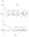
- a temperature sensor is arranged in the room to be cooled, which provides the temperature profile in the cooling room shown in FIGS. 1 and 2.
- the cooling unit is switched on at time 0 in FIG. 1, after which a predetermined setpoint of -18 ° C. is reached after a certain time.
- a timer t1 is set in run by a timer, after which the temperature determined by the temperature sensor is queried.
- This at the end of t1 queried temperature T x is a certain amount below the setpoint of -18 ° C.
- the measured temperature T x is stored in an electronic device.
- the cooling unit is switched off by the electronic control device, so that the temperature at the temperature sensor rises again.
- a time t 2 is started, when the temperature sensor expires, a query is made as to whether the temperature has reached or exceeded the setpoint. If the temperature determined when t2 has expired is above the setpoint, the cooling unit is switched on again, so that the temperature at the temperature sensor drops again. As soon as the setpoint is determined on the temperature sensor, the time t 1 is started again and when it expires the temperature is queried on the temperature sensor. If, for example, a temperature T ' x is measured below the target value, this temperature T' x is stored and compared with the previously measured temperature T x . At the same time, the cooling unit is switched off again and the time t2 started.
- both temperatures T x and T' x remain stored, whereupon a query is made again after the end of t2 whether the temperature has reached or exceeded the setpoint. If this is the case, the cooling unit is switched on again, whereupon the time t 1 is started again when the setpoint is reached and when the temperature expires the temperature sensor is queried.
- the temperature T ⁇ x below the setpoint is again stored and compared with the two previous temperatures T x and T ' x . If the comparison shows that all three temperatures are the same, it is deduced from this that a stable state has occurred in the refrigerator compartment.
- the interrogation cycle is terminated and the temperature difference ⁇ T between the setpoint and T x is determined, whereupon the temperature difference above and below the setpoint is set as the limit for switching the cooling unit on and off, as shown in FIG. 1 by dashed lines above and below the setpoint T e and T a is indicated.
- the cooling unit has been switched off when querying T ⁇ x , the temperature at the temperature sensor rises above the setpoint again after a certain time, but then the cooling unit is only switched on again when the upper limit value T e is reached, which is ⁇ T above the setpoint lies.
- the cooling unit is only switched off again when the lower limit value T a is determined on the temperature sensor, which is below the target value by the amount ⁇ T.
- the temperature difference of 2 ⁇ T between the switch-on and switch-off temperatures T e and T a on both sides of the setpoint is maintained until the next defrosting process of the cooling unit or until the next change in operation, whereupon the described process is repeated when a new operating phase of the cooling unit starts again, again by the temperature difference 2 ⁇ T to be determined and determined for further operation.
- the previous temperatures T x and T' x are stored in the memory electronic control device deleted, only the value T ⁇ x is retained in the memory.
- the query process is repeated until a sequence of three identical temperatures T x is determined. As long as three successive values T x are not the same, it is assumed that a stable state has not yet occurred in the cold room. Instead of three successive values T x , two or four or more can also be specified, which must be the same in order to recognize a stable state and to determine the temperature difference 2 ⁇ T.
- a restart interlock in the form of a time relay is usually provided, which only then permits restarting after the unit has been switched off. when a predetermined time of 180 s has elapsed, for example.
- Such a restart interlock protects the motor of the cooling unit from damage caused by an excessive number of starts.
- the time t2 given in the preceding example must therefore be greater than or equal to the time of, for example, 180 s of the restart interlock.
- the time t 1 can for example be set to 300 s. But it is also possible to set t1 to, for example, 180 s, taking into account the minimum runtime specified by the unit manufacturer.
- a tolerance limit of, for example, +/- 0.5 ° C. is expediently set, within which a following measured value T ′ x or T ⁇ x is regarded as being equal to T x . If, in the second or third measurement, the comparison value is outside the tolerance of +/- 0.5 ° C, for example caused by load fluctuations in the refrigerator, the sequence of three measurements described above is started again with the last comparison value.
- the temperature difference between the switch-on temperature T e and the switch-off temperature T a is set by the system builder by feel, whereby this permanently set temperature difference corresponds at most to an operating state, but not to the varying operating states that occur during the operation of a cooling system.
- the automatic adjustment of the temperature difference between the switch-on and switch-off temperature or the switching frequency to the load condition is expediently carried out in a cooling system after each defrosting process, which experience has shown to occur every 8 to 24 hours.
- the control method described is not used, but rather only if the temperature conditions remain constant over longer periods of time. This is usually the case after defrosting in cooling systems.
- the control process was described using a cooling unit, but it is also possible to control a heating unit in the same way, especially in connection with a heat pump, whereby the temperature difference between the heating unit's on and off temperature is set depending on the heating load.
- the measured temperature values T x are above a predetermined target value, as are the switch-off temperature T a above the target value and the switch-on temperature T e below the target value.
- a room temperature or a media temperature can be queried, stored and compared, as is also the case with a cooling unit.
- the water temperature in a boiler or the oil temperature in an oil cooler can be measured in connection with a heat pump.
- the cooling unit is switched on and off at short intervals, because the limit value T a is reached more quickly after reaching T e due to the insufficient cooling load.
- the cooling unit can be switched on and off up to the switching frequency limit and above.
- the control method described determines a new, larger temperature difference between the switch-on and switch-off temperatures at the latest after a defrosting process, so that the switching frequency is automatically reduced.
Landscapes
- Engineering & Computer Science (AREA)
- Physics & Mathematics (AREA)
- General Physics & Mathematics (AREA)
- Automation & Control Theory (AREA)
- General Engineering & Computer Science (AREA)
- Thermal Sciences (AREA)
- Chemical & Material Sciences (AREA)
- Mechanical Engineering (AREA)
- Combustion & Propulsion (AREA)
- Devices That Are Associated With Refrigeration Equipment (AREA)
- Waste-Gas Treatment And Other Accessory Devices For Furnaces (AREA)
- Crystals, And After-Treatments Of Crystals (AREA)
- Central Heating Systems (AREA)
- Control Of Temperature (AREA)
Priority Applications (1)
| Application Number | Priority Date | Filing Date | Title |
|---|---|---|---|
| AT89102436T ATE95326T1 (de) | 1988-02-11 | 1989-02-13 | Verfahren zum einstellen der temperaturdifferenz zwischen ein- und ausschalttemperatur eines kuehlaggregats. |
Applications Claiming Priority (2)
| Application Number | Priority Date | Filing Date | Title |
|---|---|---|---|
| DE3804258A DE3804258C1 (fr) | 1988-02-11 | 1988-02-11 | |
| DE3804258 | 1988-02-11 |
Publications (3)
| Publication Number | Publication Date |
|---|---|
| EP0336076A2 true EP0336076A2 (fr) | 1989-10-11 |
| EP0336076A3 EP0336076A3 (en) | 1990-05-23 |
| EP0336076B1 EP0336076B1 (fr) | 1993-09-29 |
Family
ID=6347204
Family Applications (1)
| Application Number | Title | Priority Date | Filing Date |
|---|---|---|---|
| EP89102436A Expired - Lifetime EP0336076B1 (fr) | 1988-02-11 | 1989-02-13 | Méthode de réglage de la diffèrence de la température d'enclenchement et de déclenchement d'un aggrégat de refroidissement |
Country Status (5)
| Country | Link |
|---|---|
| US (1) | US4934593A (fr) |
| EP (1) | EP0336076B1 (fr) |
| JP (1) | JPH01266609A (fr) |
| AT (1) | ATE95326T1 (fr) |
| DE (1) | DE3804258C1 (fr) |
Families Citing this family (19)
| Publication number | Priority date | Publication date | Assignee | Title |
|---|---|---|---|---|
| US5197670A (en) * | 1991-10-24 | 1993-03-30 | Thermo King Corporation | Method of operating a transport refrigeration unit |
| DE4445191C2 (de) * | 1994-12-17 | 1999-07-22 | Eberspaecher J Gmbh & Co | Verfahren zur Steuerung eines Heizgeräts |
| KR0180596B1 (ko) * | 1995-05-10 | 1999-05-01 | 정몽원 | 냉동저장고의 온도 보상방법 |
| KR0162404B1 (ko) * | 1995-09-22 | 1999-01-15 | 구자홍 | 공기조화기의 각성 제어방법 |
| KR970028212A (ko) * | 1995-11-24 | 1997-06-24 | 구자홍 | 학습효율 향상을 위한 에어콘의 각성공조 제어방법 |
| DE19725868C2 (de) * | 1997-06-18 | 1999-04-15 | Liebherr Hausgeraete | Verfahren zur Anzeige der Temperatur eines Kühl- und/oder Gefriergeräts |
| SE513258C2 (sv) * | 1998-11-05 | 2000-08-07 | Electrolux Ab | Sätt och anordning för styrning av en temperatur i ett skåp |
| JP4571762B2 (ja) * | 2001-07-13 | 2010-10-27 | 株式会社リコー | サーディップ型固体撮像素子 |
| US7270098B2 (en) * | 2002-07-15 | 2007-09-18 | Teleflex Canada Inc. | Vehicle heater and controls therefor |
| US6766962B2 (en) * | 2002-07-15 | 2004-07-27 | Teleflex Canada Limited Partnership | Temperature maintaining apparatus and temperature control apparatus and method therefor |
| US6772722B2 (en) | 2002-07-15 | 2004-08-10 | Teleflex Canada Limited Partnership | Heater and burner head assembly and control module therefor |
| US7337620B2 (en) * | 2005-05-18 | 2008-03-04 | Whirlpool Corporation | Insulated ice compartment for bottom mount refrigerator |
| JP5254559B2 (ja) * | 2007-02-23 | 2013-08-07 | 三菱重工業株式会社 | 空気調和装置および自動暖房運転制御方法 |
| JP5116607B2 (ja) * | 2008-08-18 | 2013-01-09 | 株式会社日立製作所 | ガス遮断器 |
| JP5779108B2 (ja) * | 2012-01-14 | 2015-09-16 | トミー工業株式会社 | 電気機器 |
| DE102012002654A1 (de) * | 2012-02-10 | 2013-08-14 | Liebherr-Hausgeräte Ochsenhausen GmbH | Kühl- und/oder Gefriergerät |
| CN106959040B (zh) * | 2017-04-28 | 2023-02-17 | 山东中实易通集团有限公司 | 空气预热器冷端综合温度控制方法、系统及空气预热器 |
| CN111365938B (zh) * | 2020-03-20 | 2021-07-16 | 长虹美菱股份有限公司 | 用于独立制冷系统间室暖藏的精确控温的方法 |
| CN116643602B (zh) * | 2023-04-07 | 2025-10-28 | 武汉汉立制冷科技股份有限公司 | 一种激光制冷系统控制温差自适应修正方法 |
Family Cites Families (12)
| Publication number | Priority date | Publication date | Assignee | Title |
|---|---|---|---|---|
| US4172555A (en) * | 1978-05-22 | 1979-10-30 | Levine Michael R | Adaptive electronic thermostat |
| CH637753A5 (de) * | 1979-01-26 | 1983-08-15 | Elektrowatt Ag | Schaltungsanordnung zum bestimmen des optimalen einschaltzeitpunktes einer heizungs- oder klimaanlage. |
| US4257318A (en) * | 1979-04-30 | 1981-03-24 | Mcquay-Perfex Inc. | Variable dead band pressure control system |
| US4689967A (en) * | 1985-11-21 | 1987-09-01 | American Standard Inc. | Control and method for modulating the capacity of a temperature conditioning system |
| JPS56118114A (en) * | 1980-02-22 | 1981-09-17 | Matsushita Electric Ind Co Ltd | Temperature controller |
| US4325225A (en) * | 1980-07-28 | 1982-04-20 | Eaton Corporation | Electronic temperature control |
| US4356962A (en) * | 1980-11-14 | 1982-11-02 | Levine Michael R | Thermostat with adaptive operating cycle |
| US4373663A (en) * | 1981-12-10 | 1983-02-15 | Honeywell Inc. | Condition control system for efficient transfer of energy to and from a working fluid |
| DE3207815A1 (de) * | 1982-03-04 | 1983-09-15 | Siemens AG, 1000 Berlin und 8000 München | Regeleinrichtung fuer regelstrecken mit veraenderlicher streckenverstaerkung |
| DE3516142C2 (de) * | 1984-05-29 | 1995-12-14 | Vaillant Joh Gmbh & Co | 2-Punkt-Regelverfahren für eine Wärmequelle |
| CH667147A5 (de) * | 1985-01-10 | 1988-09-15 | Landis & Gyr Ag | Verfahren und einrichtung zur selbsttaetigen ermittlung der dauer einer schnellaufheizung. |
| US4674027A (en) * | 1985-06-19 | 1987-06-16 | Honeywell Inc. | Thermostat means adaptively controlling the amount of overshoot or undershoot of space temperature |
-
1988
- 1988-02-11 DE DE3804258A patent/DE3804258C1/de not_active Expired
-
1989
- 1989-02-10 US US07/309,770 patent/US4934593A/en not_active Expired - Fee Related
- 1989-02-13 AT AT89102436T patent/ATE95326T1/de not_active IP Right Cessation
- 1989-02-13 JP JP1034867A patent/JPH01266609A/ja active Pending
- 1989-02-13 EP EP89102436A patent/EP0336076B1/fr not_active Expired - Lifetime
Also Published As
| Publication number | Publication date |
|---|---|
| DE3804258C1 (fr) | 1989-09-14 |
| EP0336076A3 (en) | 1990-05-23 |
| ATE95326T1 (de) | 1993-10-15 |
| EP0336076B1 (fr) | 1993-09-29 |
| JPH01266609A (ja) | 1989-10-24 |
| US4934593A (en) | 1990-06-19 |
Similar Documents
| Publication | Publication Date | Title |
|---|---|---|
| EP0336076A2 (fr) | Méthode de réglage de la diffèrence de la température d'enclenchement et de déclenchement d'un aggrégat de refroidissement | |
| DE19828061C1 (de) | Verfahren zur Regelung der Temperatur eines Kühlmöbels und Temperaturregelvorrichtung für ein Kühlmöbel | |
| DE3713869A1 (de) | Regelgeraet fuer die ueberhitzungstemperatur des verdampfers einer kaelte- oder waermepumpanlage | |
| DE3517221C2 (fr) | ||
| EP0410330A2 (fr) | Procédé et dispositif de fonctionnement d'une installation frigorifique | |
| EP0328151B1 (fr) | Procédé de commande pour chauffage en particulier pour un chauffage de dégivrage d'installations frigorifiques | |
| DE3517218A1 (de) | Verfahren zum betreiben einer dampfkompressionskaelteanlage und anordnung zum steuern derselben | |
| DE3517219A1 (de) | Betriebsverfahren und steueranordnung fuer eine kaelteanlage | |
| EP2104811B1 (fr) | Appareil réfrigérant et procédé de commande | |
| DE2262039B2 (de) | Vorrichtung zur automatischen Steuerung des Abtauens des Verdampfers eines Kühlgerätes | |
| EP0142663A2 (fr) | Procédé et dispositif de commande du dégivrage pour pompes à chaleur | |
| DE69920350T2 (de) | Selbstregelvorrichtung zum Steuern von Kühlschränken und Gefrierapparaten | |
| EP0727628B1 (fr) | Système de contrôle et méthode de contrôle de température pour réfrigérateurs | |
| EP0328152A2 (fr) | Procédé de commande de fonctionnement d'un groupe frigorifique | |
| DE4114700C2 (fr) | ||
| EP0152608A2 (fr) | Procédé de commande d'une installation frigorifique complexe | |
| EP3400410B1 (fr) | Procédé pour faire fonctionner un compresseur frigorifique à moteur électrique à vitesse variable | |
| DE2717050C3 (de) | Kompressor-Kälteanlagen mit zwei Abteilen unterschiedlicher Temperatur | |
| WO2018100166A1 (fr) | Procédé pour faire fonctionner un compresseur frigorifique à vitesse variable | |
| EP1813897A2 (fr) | Procédé et dispositif destinés à la fabrication de bandes de matière fibreuse multicouches | |
| EP2039903A2 (fr) | Procédé de détermination d'une capacité de puissance d'un système de refroidissement | |
| CH691236A5 (de) | Verfahren zum Betrieb eines Haushalts-Kühlschrankes. | |
| EP1178271B1 (fr) | Commande électronique pour appareils de refroidissement ou de congélation | |
| EP2652409B1 (fr) | Procédé permettant de faire fonctionner un système de pompe à chaleur | |
| WO2012059334A2 (fr) | Appareil de froid |
Legal Events
| Date | Code | Title | Description |
|---|---|---|---|
| PUAI | Public reference made under article 153(3) epc to a published international application that has entered the european phase |
Free format text: ORIGINAL CODE: 0009012 |
|
| AK | Designated contracting states |
Kind code of ref document: A2 Designated state(s): AT FR GB IT NL SE |
|
| PUAL | Search report despatched |
Free format text: ORIGINAL CODE: 0009013 |
|
| AK | Designated contracting states |
Kind code of ref document: A3 Designated state(s): AT FR GB IT NL SE |
|
| 17P | Request for examination filed |
Effective date: 19901015 |
|
| 17Q | First examination report despatched |
Effective date: 19920518 |
|
| GRAA | (expected) grant |
Free format text: ORIGINAL CODE: 0009210 |
|
| AK | Designated contracting states |
Kind code of ref document: B1 Designated state(s): AT FR GB IT NL SE |
|
| REF | Corresponds to: |
Ref document number: 95326 Country of ref document: AT Date of ref document: 19931015 Kind code of ref document: T |
|
| ITF | It: translation for a ep patent filed | ||
| ET | Fr: translation filed | ||
| GBT | Gb: translation of ep patent filed (gb section 77(6)(a)/1977) |
Effective date: 19940125 |
|
| PLBE | No opposition filed within time limit |
Free format text: ORIGINAL CODE: 0009261 |
|
| STAA | Information on the status of an ep patent application or granted ep patent |
Free format text: STATUS: NO OPPOSITION FILED WITHIN TIME LIMIT |
|
| 26N | No opposition filed | ||
| EAL | Se: european patent in force in sweden |
Ref document number: 89102436.6 |
|
| PGFP | Annual fee paid to national office [announced via postgrant information from national office to epo] |
Ref country code: AT Payment date: 20010220 Year of fee payment: 13 |
|
| PGFP | Annual fee paid to national office [announced via postgrant information from national office to epo] |
Ref country code: SE Payment date: 20010221 Year of fee payment: 13 |
|
| REG | Reference to a national code |
Ref country code: GB Ref legal event code: IF02 |
|
| PG25 | Lapsed in a contracting state [announced via postgrant information from national office to epo] |
Ref country code: AT Free format text: LAPSE BECAUSE OF NON-PAYMENT OF DUE FEES Effective date: 20020213 |
|
| PG25 | Lapsed in a contracting state [announced via postgrant information from national office to epo] |
Ref country code: SE Free format text: LAPSE BECAUSE OF NON-PAYMENT OF DUE FEES Effective date: 20020214 |
|
| PGFP | Annual fee paid to national office [announced via postgrant information from national office to epo] |
Ref country code: FR Payment date: 20020221 Year of fee payment: 14 |
|
| PGFP | Annual fee paid to national office [announced via postgrant information from national office to epo] |
Ref country code: GB Payment date: 20020225 Year of fee payment: 14 |
|
| PGFP | Annual fee paid to national office [announced via postgrant information from national office to epo] |
Ref country code: NL Payment date: 20020226 Year of fee payment: 14 |
|
| EUG | Se: european patent has lapsed |
Ref document number: 89102436.6 |
|
| PG25 | Lapsed in a contracting state [announced via postgrant information from national office to epo] |
Ref country code: GB Free format text: LAPSE BECAUSE OF NON-PAYMENT OF DUE FEES Effective date: 20030213 |
|
| PG25 | Lapsed in a contracting state [announced via postgrant information from national office to epo] |
Ref country code: NL Free format text: LAPSE BECAUSE OF NON-PAYMENT OF DUE FEES Effective date: 20030901 |
|
| GBPC | Gb: european patent ceased through non-payment of renewal fee | ||
| PG25 | Lapsed in a contracting state [announced via postgrant information from national office to epo] |
Ref country code: FR Free format text: LAPSE BECAUSE OF NON-PAYMENT OF DUE FEES Effective date: 20031031 |
|
| NLV4 | Nl: lapsed or anulled due to non-payment of the annual fee |
Effective date: 20030901 |
|
| REG | Reference to a national code |
Ref country code: FR Ref legal event code: ST |
|
| PG25 | Lapsed in a contracting state [announced via postgrant information from national office to epo] |
Ref country code: IT Free format text: LAPSE BECAUSE OF NON-PAYMENT OF DUE FEES Effective date: 20050213 |
|
| PGFP | Annual fee paid to national office [announced via postgrant information from national office to epo] |
Ref country code: IT Payment date: 20070605 Year of fee payment: 19 |
|
| PGRI | Patent reinstated in contracting state [announced from national office to epo] |
Ref country code: IT Effective date: 20091201 |
|
| PGRI | Patent reinstated in contracting state [announced from national office to epo] |
Ref country code: IT Effective date: 20091201 |