EP0336096B1 - Vitrage sans cadre - Google Patents
Vitrage sans cadre Download PDFInfo
- Publication number
- EP0336096B1 EP0336096B1 EP19890103190 EP89103190A EP0336096B1 EP 0336096 B1 EP0336096 B1 EP 0336096B1 EP 19890103190 EP19890103190 EP 19890103190 EP 89103190 A EP89103190 A EP 89103190A EP 0336096 B1 EP0336096 B1 EP 0336096B1
- Authority
- EP
- European Patent Office
- Prior art keywords
- glazing
- holders
- pane
- facade
- holder
- Prior art date
- Legal status (The legal status is an assumption and is not a legal conclusion. Google has not performed a legal analysis and makes no representation as to the accuracy of the status listed.)
- Expired - Lifetime
Links
- 239000000853 adhesive Substances 0.000 claims description 19
- 230000001070 adhesive effect Effects 0.000 claims description 19
- 229920002379 silicone rubber Polymers 0.000 claims description 5
- 239000002184 metal Substances 0.000 claims description 4
- 239000013013 elastic material Substances 0.000 claims description 2
- 230000002093 peripheral effect Effects 0.000 claims description 2
- XUIMIQQOPSSXEZ-UHFFFAOYSA-N Silicon Chemical compound [Si] XUIMIQQOPSSXEZ-UHFFFAOYSA-N 0.000 claims 1
- 229910000831 Steel Inorganic materials 0.000 claims 1
- 229910052710 silicon Inorganic materials 0.000 claims 1
- 239000010703 silicon Substances 0.000 claims 1
- 239000010959 steel Substances 0.000 claims 1
- 125000006850 spacer group Chemical group 0.000 description 15
- 229920001296 polysiloxane Polymers 0.000 description 7
- 229920001971 elastomer Polymers 0.000 description 6
- 239000000806 elastomer Substances 0.000 description 6
- 239000004945 silicone rubber Substances 0.000 description 4
- 239000011521 glass Substances 0.000 description 3
- 238000007789 sealing Methods 0.000 description 3
- 230000005540 biological transmission Effects 0.000 description 1
- 238000010276 construction Methods 0.000 description 1
- 229910001220 stainless steel Inorganic materials 0.000 description 1
- 239000010935 stainless steel Substances 0.000 description 1
- 230000003068 static effect Effects 0.000 description 1
Images



Classifications
-
- E—FIXED CONSTRUCTIONS
- E06—DOORS, WINDOWS, SHUTTERS, OR ROLLER BLINDS IN GENERAL; LADDERS
- E06B—FIXED OR MOVABLE CLOSURES FOR OPENINGS IN BUILDINGS, VEHICLES, FENCES OR LIKE ENCLOSURES IN GENERAL, e.g. DOORS, WINDOWS, BLINDS, GATES
- E06B3/00—Window sashes, door leaves, or like elements for closing wall or like openings; Layout of fixed or moving closures, e.g. windows in wall or like openings; Features of rigidly-mounted outer frames relating to the mounting of wing frames
- E06B3/66—Units comprising two or more parallel glass or like panes permanently secured together
- E06B3/6617—Units comprising two or more parallel glass or like panes permanently secured together one of the panes being larger than another
-
- E—FIXED CONSTRUCTIONS
- E06—DOORS, WINDOWS, SHUTTERS, OR ROLLER BLINDS IN GENERAL; LADDERS
- E06B—FIXED OR MOVABLE CLOSURES FOR OPENINGS IN BUILDINGS, VEHICLES, FENCES OR LIKE ENCLOSURES IN GENERAL, e.g. DOORS, WINDOWS, BLINDS, GATES
- E06B3/00—Window sashes, door leaves, or like elements for closing wall or like openings; Layout of fixed or moving closures, e.g. windows in wall or like openings; Features of rigidly-mounted outer frames relating to the mounting of wing frames
- E06B3/54—Fixing of glass panes or like plates
- E06B3/5427—Fixing of glass panes or like plates the panes mounted flush with the surrounding frame or with the surrounding panes
Definitions
- the invention relates to frameless glazing (structural glazing), the edge regions of single or multi-pane glazing being attached to elements of the facade, such as facade posts and transoms, or element facades via load-bearing seals, in particular made of silicone rubber (see EP-A-0251834).
- glazing is framelessly attached on two or four sides to facade profiles, such as facade posts and facade bars.
- the glazing consists of a pane or insulating glazing made of two or more panes and is sealed directly onto the elements of the facades, the sealing not only performing a sealing function, but also providing static functions, such as the transmission of wind loads (wind pressure and wind suction) , and partly also carries the weight of the glazing.
- the sealing is done in particular with a one- or two-component silicone rubber.
- the invention has for its object to provide a frameless glazing, in which it is ensured that in the event of a fire, the pane or panes cannot fall off the building as a whole.
- This object is achieved in that between the elements of the facades and at least the outer pane holder are arranged, which are attached to the glazing with a highly heat-resistant adhesive, and do not exert constraints on the glazing when the load-bearing seal is intact.
- the arrangement of holders ensures that after a failure of the load-bearing seal in the event of a fire, the glazing cannot fall down as a whole, but is held and, if necessary, broken into smaller pieces by the action of heat.
- Available high heat resistant adhesives are able to maintain their function at temperatures up to 1600 ° C and more. Temperatures of up to approx. 1200 ° C occur during the prescribed fire tests, so that adequate safety is guaranteed.
- the silicone bonding takes over the removal of forces such as wind, temperature and sometimes. Own weight.
- the glued brackets secure the pane.
- the holders are preferably designed such that they can follow movements of the load-bearing seal, so that no constraints are exerted on the glazing when the silicone bond is flexible.
- holders are arranged on the elements of the facade with play, so that a shift in the direction perpendicular to the plane of the glazing can take place.
- a layer made of an elastic material preferably silicone, is arranged between a holder and a facade element, and the holder is slidably held on a screw or the like.
- the holders are preferably of I, T, L or double T shape in cross section and engage in appropriately designed grooves or undercuts on the elements of the facade, such as facade posts and ledgers or on the element facades.
- the holders are designed as springs and glued to the back or the peripheral edge of the outer pane of the glazing.
- the holders are preferably made of metal and in particular stainless steel, so that cold bridges are avoided.
- the outer pane of the glazing is secured by four brackets arranged at the corner areas.
- Fig. 1 shows a plan view of a glazing 10, which is glued to a facade post 12 and facade bolts 14 via a load-bearing seal made of silicone rubber.
- the glazing 10 can consist of a single pane or be designed as multiple glazing.
- holders 16 are provided between the facade bars 14 and the back of the glazing 10, which are glued to the glazing 10 by means of a highly heat-resistant adhesive and by conventional fastening means such as screws, rivets or ..., Are attached to the facade bars 14.
- FIG. 2 shows in cross section the edge region of a glazing 20, which consists of an outer pane 22 and an inner pane 24.
- a spacer 26 made of an elastomer is arranged between the disks 22, 24.
- the disks 22, 24 are connected to one another via a load-bearing seal 28.
- the inner pane 24 is fastened to the outside of a transom 32 of an element facade via a load-bearing seal 30.
- a spacer 34 made of an elastomer is provided between the latch 32 and the washer 24.
- a metal profile 38 which is used to fasten the outer pane 22 of the glazing 20, is arranged on the latch 34 via insulating rails 36.
- the profile 38 has an undercut groove 40, in which a cross-sectionally double-T-shaped holder 42 is slidably held, as can be seen in particular from FIG. 3.
- a load-bearing seal 44 is provided between the edge region of the pane 22 and the profile 38.
- the outside 46 of the holder 42 is glued to the back of the disk 22 using a highly heat-resistant adhesive (HT adhesive) 48.
- HT adhesive highly heat-resistant adhesive
- a washer 52 is arranged on which the edge surface of the washer 24 is supported.
- the holder 42 which is glued on via the heat-resistant adhesive 48, ensures that the pane 22 and thus the pane 24 of the glazing 20 is also held until it shatters as a result of the heat. This prevents the glazing 20 as a whole from falling off the facade after failure of the load-bearing seals 28, 30, 44.
- seals 70 are provided for fastening the panes to the elements of the facade or to each other , 72 and 74 are provided.
- the glazing 60 is secured in the event of a fire by means of a holder 76 which, with its hook-shaped inner end 78, can be moved in a groove 80 on the profile 64.
- the outer end face 82 of the holder 76 is glued to the back of the outer pane 88 of the glazing 60 by means of a highly heat-resistant adhesive (HT adhesive) 84, so that a securing of the glazing 60 is ensured in the event of a fire.
- HT adhesive highly heat-resistant adhesive
- the engagement of the hook-shaped end 78 of the holder 76 in the groove 80 on the profile 64 is ensured by a block 90, which at the same time serves as a spacer between the inner pane of the glazing 60 and profile 64.
- a spacer 92 is arranged between the panes of the glazing and a spacer 94 made of elastomer is arranged between the outer pane 88 and the profile 66.
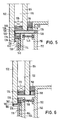
- FIG. 5 shows in cross section the edge region of a glazing 100 consisting of an outer pane 102 and an inner pane 104, which are held together by a spacer 106 and a load-bearing seal 108.
- the glazing 100 is fastened to an element 110 of the facade, consisting of an inner profile 112 and an outer profile 114, which are connected to one another via insulating rails 146, via load-bearing seals 116 and 118.
- a spacer 120 is arranged between the disk 102 and the profile 114 and a spacer 122 is arranged between the inner disk 104 and the profile 112.
- the profile 112 is formed with a recess 124 into which the end of a holder 126 engages, which supports the inner pane 104 and is glued to the rear face of the outer pane 102 by means of a heat-resistant adhesive 130 with its outer end face 128.
- a further securing of the pane 102 takes place via a holder 132, which is approximately L-shaped in cross section and is glued to the end face of its leg 134 via a highly heat-resistant adhesive 136 to the edge region of the pane 102.
- the holder 132 is or the like via fastening means 138 such as screws.
- a layer 140 of silicone is arranged between the holder 132 and the profile 114, so that the holder 132 can perform movements perpendicular to the plane of the glazing 100 in order to be able to follow the movements of the load-bearing seals 118 and 116 , ie he or the like on the screw. slide.
- the insulating glazing 150 shown in FIG. 6, consisting of an outer pane 152 and an inner pane 154, is fastened to an element 156 of the facade via load-bearing seals 158 and 160.
- the element 156 consists of an inner profile 162 and an outer profile 164, which are connected to one another via insulating rails 166.
- a spacer 168 is arranged between the inner disk 154 and the inner profile 162 and a spacer 170 is arranged between the outer disk 152 and the outer profile 164.
- the washers 152 and 154 are connected to one another via a spacer 172 made of an elastomer and a load-bearing seal 174.
- the glazing 150 is held on the element 156 until, as a result of the Exposure to heat cracks, a holder 176 or screws 178 or the like. attached to the profile 164, which supports the outer pane 152 with an angled leg 180 and is connected to the edge surface of the pane 152 by means of a highly heat-resistant adhesive 182. Between the back of the holder 176 and the front of the profile 164 there is a layer 184 made of a silicone so that the holder 176 can take part in the movements caused by the resilience of the load-bearing seals 158 and 160 and the connection between the holder 176 and the washer 152 remains guaranteed . In the event of a fire, after the load-bearing seals 158 and 160 have failed, the glued-on holder 176 takes over the securing function, so that the glazing cannot fall down as a whole surface.
- FIG. 7 shows a glazing 200 consisting of an outer pane 202 and an inner pane 204, which are connected to one another via a spacer 206 and a load-bearing seal 208.
- Glazing 200 is attached to an element of the facade without a frame, which consists of an inner profile 212 and an outer profile 214, which are connected to one another via insulating rails 216.
- the glazing 200 is fastened to the facade element 200 via load-bearing seals 218 and 220 and spacers 222 and 224 made of an elastomer.
- a corrugated leaf spring 226 is fastened to the inner profile 212 with an edge as a holder, the opposite edge 228 of which with a highly heat-resistant adhesive 230 is attached to the back of the pane 202 Glazing 200 is connected.
- the spring 226 is able to participate in movements of the glazing 200 and, in the event of a fire, after the load-bearing seals 218 and 220 have failed, assumes a holding function for the glazing 200 until it breaks into pieces.
- FIG. 8 corresponds to the embodiment shown in FIG. 7 with the difference that the holder in the form of a spring 232 is connected to a region of the lower edge surface 236 of the outer pane of a glazing via a highly heat-resistant adhesive 234.
- the spring 232 is or the like via screws 238. attached to the outer profile of an element of the facade.
- several springs can be arranged on the lower edges and the upper edges of a glazing in order to ensure that the glazing stays on the facade in the event of a fire.
- Fig. 9 corresponds essentially to the embodiment of FIG. 8 with the difference that as a holder a spring or springs 240 with an edge area 242 glued to the rear of the outer pane 244 of a glazing 246 by means of a highly heat-resistant adhesive (HT adhesive) 248 is.
- HT adhesive highly heat-resistant adhesive
- step glazing that is, the dimensions of the outer pane, at least in the vertical direction, are larger than the inner pane of the glazing, so that both the inner and the outer pane are directly attached to the Facade mullion or transom or element of the facade can be done.
- the glazing 250 shown in FIG. 10 is not designed as step glazing, ie the dimensions of the outer pane 252 correspond to the dimensions of the inner pane 254.
- the panes 252 and 254 are connected to one another via a spacer 256 and a load-bearing seal 258.
- the glazing 250 is fastened to a facade post or transom 260, in that a spacer 262 made of an elastomer and a supporting seal 264 are arranged between the inner pane 252 and the outside of the facade post or transom 260.
- a spring 266 via screws 268 or the like is on the facade post or bar 260 as a holder. attached.
- the other end of the corrugated leaf spring 266 is adhered to the lower edge surface 272 of the outer disc 252 by a highly heat-resistant adhesive 270. If the load-bearing seals fail in the event of a fire, the spring 266 takes over the holding function for the glazing 250 until the panes of the glazing burst and fall piece by piece from the facade.
- FIG. 11 corresponds essentially to the embodiment shown in Fig. 10 with the difference that instead of a facade post or transom an element 280 of the facade is provided, which consists of an inner profile 282 and an outer profile 284, which are connected to one another via insulating rails 286.
- the structure and the fastening of the glazing 288 to the element 280 is analogous to FIG. 10.
- a corrugated leaf spring 290 is fastened to the outer profile 284 as a holder, which is glued to the outer pane 294 of the glazing 288 with an edge region via a highly heat-resistant adhesive 292 is.
- the spring 290 assumes a holding function if the load-bearing seals between the panes and the glazing 288 and the element 280 fail in the event of a fire.
- FIG. 12 shows in cross section an L-shaped leaf spring 296 which is fastened to an element 300 of the facade by means of screws 298, a layer 302, for example made of silicone, being arranged between the spring 296 serving as the holder and the element 300.
- the spring 296 is glued with its short leg 304 to a pane of glazing (not shown) using a highly heat-resistant adhesive 306.
Landscapes
- Engineering & Computer Science (AREA)
- Civil Engineering (AREA)
- Structural Engineering (AREA)
- Special Wing (AREA)
- Load-Bearing And Curtain Walls (AREA)
Claims (10)
Applications Claiming Priority (4)
| Application Number | Priority Date | Filing Date | Title |
|---|---|---|---|
| DE3808980 | 1988-03-17 | ||
| DE3808980 | 1988-03-17 | ||
| DE3817309 | 1988-05-20 | ||
| DE19883817309 DE3817309A1 (de) | 1988-03-17 | 1988-05-20 | Rahmenlose verglasung |
Publications (2)
| Publication Number | Publication Date |
|---|---|
| EP0336096A1 EP0336096A1 (fr) | 1989-10-11 |
| EP0336096B1 true EP0336096B1 (fr) | 1991-12-18 |
Family
ID=25866062
Family Applications (1)
| Application Number | Title | Priority Date | Filing Date |
|---|---|---|---|
| EP19890103190 Expired - Lifetime EP0336096B1 (fr) | 1988-03-17 | 1989-02-23 | Vitrage sans cadre |
Country Status (2)
| Country | Link |
|---|---|
| EP (1) | EP0336096B1 (fr) |
| DE (1) | DE3817309A1 (fr) |
Families Citing this family (2)
| Publication number | Priority date | Publication date | Assignee | Title |
|---|---|---|---|---|
| DE4024045C2 (de) * | 1990-07-28 | 1995-04-06 | Ritter Aluminium Gmbh | Fenster- oder Türflügel |
| FR2755464B1 (fr) * | 1996-11-07 | 1999-01-15 | Bluntzer Sa | Dispositif d'accrochage et de securite destine a assurer un maintien mecanique d'un vitrage exterieur normalement colle sur un chassis support |
Family Cites Families (6)
| Publication number | Priority date | Publication date | Assignee | Title |
|---|---|---|---|---|
| SE7713585L (sv) * | 1976-12-03 | 1978-06-04 | Saint Gobain | Brandbestendigt fonster |
| FR2599405B1 (fr) * | 1986-05-27 | 1991-05-24 | Ouest Sa Vitrages Isolants | Dispositif de securite pour batiment a paroi vitree |
| IT1189582B (it) * | 1986-06-19 | 1988-02-04 | Manfredo Alessi | Vetrate strutturali con giunzioni realizzate mediante sigillanti strutturali ed elementi metallici |
| DE8701055U1 (de) * | 1986-11-27 | 1987-03-12 | Josef Gartner & Co, 8883 Gundelfingen | Rahmenlose Verglasung |
| DE8704683U1 (de) * | 1987-03-30 | 1987-05-27 | GGN Glashandels-Gesellschaft Nördlingen mbH & Co KG, 8860 Nördlingen | Glasscheibe zur Verwendung als Fassadenelement für Hochbauten |
| DE8716220U1 (de) * | 1987-12-09 | 1988-04-07 | Metallbau Koller AG, Muttenz | Plattenkonstruktion für die Bildung einer Fassade od. dgl. bei einem Bauwerk |
-
1988
- 1988-05-20 DE DE19883817309 patent/DE3817309A1/de active Granted
-
1989
- 1989-02-23 EP EP19890103190 patent/EP0336096B1/fr not_active Expired - Lifetime
Also Published As
| Publication number | Publication date |
|---|---|
| DE3817309A1 (de) | 1989-10-12 |
| EP0336096A1 (fr) | 1989-10-11 |
| DE3817309C2 (fr) | 1992-12-17 |
Similar Documents
| Publication | Publication Date | Title |
|---|---|---|
| DE68902172T2 (de) | Verglasungselement fuer vorhangfassaden. | |
| EP0525690B1 (fr) | Elément pour une construction en verre et construction en verre | |
| EP0319695B1 (fr) | Panneaux de façade ou similaires pour bâtiments | |
| EP1373672B1 (fr) | Battant de fenetre ou de porte | |
| DE19938250A1 (de) | Befestigung zum Haltern einer Verbundscheibe | |
| DE69333450T2 (de) | Fenstersprosse | |
| AT396614B (de) | Isolierglaselement | |
| EP0282686A2 (fr) | Façade vitrée avec des panneaux de verre | |
| EP1566514B1 (fr) | Vitrage pare-feu en plusieurs parties avec un dormant pour fenêtre ou porte | |
| EP1020577B1 (fr) | Façade ou toiture vitrée avec des panneaux vitrés ou de remplissage décalés par rapport aux ferrures supportant le bord des panneaux vitrés ou de remplissage | |
| DE2308457A1 (de) | Randeinfassung fuer glasscheiben | |
| DE3808978C2 (fr) | ||
| EP0333074B1 (fr) | Vitrage structurel résistant au feu | |
| DE3817309C2 (fr) | ||
| DE3701808C2 (fr) | ||
| EP0712971B1 (fr) | Dispositif de montage et de fixation de plaques de façade | |
| DE3725853A1 (de) | Rahmenlose verglasung | |
| EP0367908A1 (fr) | Vitrage sans cadre | |
| DE8701055U1 (de) | Rahmenlose Verglasung | |
| DE3713497C1 (en) | Glazing for greenhouses or the like having border profiles, and a glass pane which can be used, in particular, for this | |
| EP0731246A1 (fr) | Vitrage à double ou multiples glaces pour couvrir une ouverture de bâtiment et support de vis résistant au feu | |
| EP3168406B1 (fr) | Élément de verre isolant et façade modulaire en verre | |
| DE3801720C2 (fr) | ||
| EP3530860B1 (fr) | Élément de verre isolant pour façade en verre et façade en verre | |
| DE4123604A1 (de) | Fassadenelement mit wenigstens einer glasscheibe |
Legal Events
| Date | Code | Title | Description |
|---|---|---|---|
| PUAI | Public reference made under article 153(3) epc to a published international application that has entered the european phase |
Free format text: ORIGINAL CODE: 0009012 |
|
| AK | Designated contracting states |
Kind code of ref document: A1 Designated state(s): ES FR GB IT NL |
|
| 17P | Request for examination filed |
Effective date: 19890912 |
|
| 17Q | First examination report despatched |
Effective date: 19910118 |
|
| GRAA | (expected) grant |
Free format text: ORIGINAL CODE: 0009210 |
|
| AK | Designated contracting states |
Kind code of ref document: B1 Designated state(s): ES FR GB IT NL |
|
| PG25 | Lapsed in a contracting state [announced via postgrant information from national office to epo] |
Ref country code: IT Free format text: LAPSE BECAUSE OF FAILURE TO SUBMIT A TRANSLATION OF THE DESCRIPTION OR TO PAY THE FEE WITHIN THE PRESCRIBED TIME-LIMIT;WARNING: LAPSES OF ITALIAN PATENTS WITH EFFECTIVE DATE BEFORE 2007 MAY HAVE OCCURRED AT ANY TIME BEFORE 2007. THE CORRECT EFFECTIVE DATE MAY BE DIFFERENT FROM THE ONE RECORDED. Effective date: 19911218 Ref country code: ES Free format text: THE PATENT HAS BEEN ANNULLED BY A DECISION OF A NATIONAL AUTHORITY Effective date: 19911218 |
|
| ET | Fr: translation filed | ||
| GBT | Gb: translation of ep patent filed (gb section 77(6)(a)/1977) | ||
| PLBE | No opposition filed within time limit |
Free format text: ORIGINAL CODE: 0009261 |
|
| STAA | Information on the status of an ep patent application or granted ep patent |
Free format text: STATUS: NO OPPOSITION FILED WITHIN TIME LIMIT |
|
| 26N | No opposition filed | ||
| PGFP | Annual fee paid to national office [announced via postgrant information from national office to epo] |
Ref country code: FR Payment date: 19990129 Year of fee payment: 11 |
|
| PGFP | Annual fee paid to national office [announced via postgrant information from national office to epo] |
Ref country code: GB Payment date: 19990225 Year of fee payment: 11 |
|
| PGFP | Annual fee paid to national office [announced via postgrant information from national office to epo] |
Ref country code: NL Payment date: 19990228 Year of fee payment: 11 |
|
| PG25 | Lapsed in a contracting state [announced via postgrant information from national office to epo] |
Ref country code: GB Free format text: LAPSE BECAUSE OF NON-PAYMENT OF DUE FEES Effective date: 20000223 |
|
| PG25 | Lapsed in a contracting state [announced via postgrant information from national office to epo] |
Ref country code: NL Free format text: LAPSE BECAUSE OF NON-PAYMENT OF DUE FEES Effective date: 20000901 |
|
| GBPC | Gb: european patent ceased through non-payment of renewal fee |
Effective date: 20000223 |
|
| PG25 | Lapsed in a contracting state [announced via postgrant information from national office to epo] |
Ref country code: FR Free format text: LAPSE BECAUSE OF NON-PAYMENT OF DUE FEES Effective date: 20001031 |
|
| NLV4 | Nl: lapsed or anulled due to non-payment of the annual fee |
Effective date: 20000901 |
|
| REG | Reference to a national code |
Ref country code: FR Ref legal event code: ST |