EP0336207A2 - Servobetätiger mit Rückkopplung und Verfahren zu dessen Kalibrierung - Google Patents
Servobetätiger mit Rückkopplung und Verfahren zu dessen Kalibrierung Download PDFInfo
- Publication number
- EP0336207A2 EP0336207A2 EP89105060A EP89105060A EP0336207A2 EP 0336207 A2 EP0336207 A2 EP 0336207A2 EP 89105060 A EP89105060 A EP 89105060A EP 89105060 A EP89105060 A EP 89105060A EP 0336207 A2 EP0336207 A2 EP 0336207A2
- Authority
- EP
- European Patent Office
- Prior art keywords
- gear
- servoactuator
- potentiometer
- plastic
- worm gear
- Prior art date
- Legal status (The legal status is an assumption and is not a legal conclusion. Google has not performed a legal analysis and makes no representation as to the accuracy of the status listed.)
- Withdrawn
Links
Images


Classifications
-
- H—ELECTRICITY
- H02—GENERATION; CONVERSION OR DISTRIBUTION OF ELECTRIC POWER
- H02K—DYNAMO-ELECTRIC MACHINES
- H02K7/00—Arrangements for handling mechanical energy structurally associated with dynamo-electric machines, e.g. structural association with mechanical driving motors or auxiliary dynamo-electric machines
- H02K7/10—Structural association with clutches, brakes, gears, pulleys or mechanical starters
-
- H—ELECTRICITY
- H01—ELECTRIC ELEMENTS
- H01C—RESISTORS
- H01C10/00—Adjustable resistors
- H01C10/14—Adjustable resistors adjustable by auxiliary driving means
-
- H—ELECTRICITY
- H02—GENERATION; CONVERSION OR DISTRIBUTION OF ELECTRIC POWER
- H02K—DYNAMO-ELECTRIC MACHINES
- H02K11/00—Structural association of dynamo-electric machines with electric components or with devices for shielding, monitoring or protection
- H02K11/20—Structural association of dynamo-electric machines with electric components or with devices for shielding, monitoring or protection for measuring, monitoring, testing, protecting or switching
- H02K11/21—Devices for sensing speed or position, or actuated thereby
Definitions
- the present inventions relates to motor driven servoactuators of the type operated by a low voltage direct current motor and employing a speed reducer to provide high torque slow rate of rotation output.
- Servoactuators of this type are known to employ a feedback potentiometer coupled to rotate with the output member for providing a variable resistance signal proportional to the rotational position of the output member.
- An example of such a device is a servoactuator employed for automotive passenger compartment temperature control systems, one such device being shown and described in U.S. Patent 4,616,164.
- the servoactuator in the aforesaid '164 patent employs a variable resistance strip on a portion of the housing with an electrical wiper contact rotated thereagainst by the output member for providing an electrical resistance signal proportional to the rotational position of the output member.
- the present invention provides a solution to the problem of designing a low cost easily assembled and calibrated servoactuator operated by a low voltage direct current motor and providing a numerically high speed reduction between the motor input and the rotational output member of the servoactuator.
- the servoactuator of the present invention employs a worm drive from the motor through four stages of gear reduction and has a potentiometer geared to the output member for providing an output position indication in the form of a variable resistance signal which nulls the motor when the output position signal matches a command input signal.
- the potentiometer of the present invention has an annular collar keyed to the potentiometer shaft and axially movable thereon.
- a floating potentiometer drive gear is engaged with the speed reducer output member gear and the potentiometer shaft is positioned to provide the desired electrical resistance signal corresponding to the position of the output member.
- the annular collar is then moved axially on the keyway to a press fit engagement with the inner periphery of the potentiometer drive gear to thereby engage the drive gear with the potentiometer shaft for providing a feedback signal.
- the servoactuator of the present invention employs a unique and novel combination of fluorinated and/or chlorinated plastic polyimide and acetal gears with a small amount of lubricant compounded therein in the speed reducer for minimizing gear train noise.
- the servoactuator of the present invention is indicated generally at 10 as having a housing comprising a lower case portion 12 having a generally hollow cupped-shape and a cover 14 secured to the lower case by suitable fasteners such as screws 16. Portions of the cover 14 have been broken away in Figure 1 to expose the inner workings of the servoactuator.
- the cover 14 has a suitable cut-out 18 provided therein for exposing the electrical connectors pins 20, 22, 24, 26, 28, 30 and 32, which are adapted for electrical connection as will hereinafter be described.
- the servoactuator has an output shaft 34 extending from the lower case portion and adapted for rotary driving connection thereto by virtue of oppositely disposed spaced flats, one of which is indicated by reference numeral 34 in Figure 2.
- the lower case portion 12 has received therein a sub-fractional horsepower direct current motor 36 which has an output shaft 38 having a worm gear 48 attached thereto.
- the worm gear 40 engages a helical gear 42 which is journalled on an axle pin 44 having one end secured to the lower case portion 12 and the other end secured in a suitable boss (not shown) provided in the underside of cover 14.
- Helical gear 42 has a pinion gear formed integrally therewith on the hub thereof as shown partially at 46 by the broken away portion of the gear 42.
- Pinion 46 engages a second stage spur gear 48 which is journalled on an axle pin 50 which has one end received in a boss provided in the lower case portion 12 and the other end of the pin received in a corresponding boss (not shown) provided in the underside of cover 14.
- Second stage spur gear 48 has formed integrally on the hub thereof a second stage pinion gear 52 which engages a third stage spur gear 54, which is journalled about pin 56 anchored at one end in lower case portion 12 and at the other end in a suitable boss (not shown) provided in the underside of cover 14.
- Third stage spur gear 54 has formed integrally therewith on the hub thereof a third stage pinion gear 58 which engages a fourth stage spur or output gear 60.
- the output gear 60 is formed integrally with the output shaft 20 (see Figure 2) which in the presently preferred practice has has a shoulder 59 provided on the periphery thereof journalled in an aperture 61 in the lower case portion 12 of the housing and on an axle pin 62 pressed therein and which is journalled in a suitable boss (not shown) provided in the underside of cover 14.
- Output gear 60 also engages a toothed ring gear 64 which is part of a potentiometer assembly as will hereinafter be described.
- a printed circuit board 66 is received in the housing lower case portion 12 and has the electrical terminals 22-32 attached thereto as shown in Figure 1 and has a portion thereof cut out to permit motor 36 to recess therein.
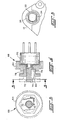
- the potentiometer assembly indicated generally at 68 is shown wherein the potentiometer 70 preferably has a resistance of 10K ohms and has a rotatable control shaft 72 extending therefrom, which shaft has a keyway 74 provided therein. Shaft 72 has received thereover in a clearance fit relationship ring gear 64 which has a precisely controlled diameter counterbore 76 provided therein. In the assembled and calibrated condition shown in solid outline in Figure 4, counterbore 76 is press fitted in interference engagement with the outside diameter of collar 78 which is keyed to shaft 72 by a key 80 received in the keyway 74.
- Calibration of the potentiometer is performed by positioning output gear 60 such that the flats on output shaft 20 have the desired rotational position with respect to the housing 12 for engagement with the device to be operated by servo 10, and positioning the shaft 72 of the potentiometer to a rotational position such that the desired percentage of full scale resistance of the potentiometer is detected electrically.
- collar 78 With the output shaft of gear 60 so positioned and with potentiometer 70 providing the desired output resistance, collar 78 is moved axially from the dashed line position shown in Figure 4 to the solid outline position shown in Figure 4 wherein the collar 78 engages the counterbore 76 of the ring gear 64 in interference press fitted engagement to thereby rotationally position the shaft 72 with respect to the ring gear 64.
- the gears in the speed reducer gear train have a ratio overall of 1500:1 and are formed of plastic material.
- Worm gear 40 is preferably formed of polyimide material having a minor fraction of fluorinated polymer or a minor fraction of fluoro-chlorinated polymer containing a lesser minor fraction of lubricant.
- the worm gear is formed of nylon material having about 18% polytetrafluoroethylene (PTFE) and about 2% silicone lubricant.
- the helical spur gears and their integrally formed pinions are formed of acetal resin having about 18% polytetrafluoroethylene and about 2% silicone oil lubricant. It will be understood that PTFE has been found satisfactory in the presently preferred practice. Other suitable fluorinated polymers for floro-chlorinated polymers may be employed in place of the PTFE.
- the electrical schematic for the servoactuator of the present invention is indicated generally at 84.
- a temperature select potentiometer 88 Upon user or vehicle operator selection of the closed position of the line power switch 86 and positioning of a temperature select potentiometer 88 provides power to the circuit at input pin 32 and receives a control signal input at pin 28 thereof through resistor R1 to junction 90.
- Junction 90 is connected to one negative input terminal of a first-half of a dual comparator U1 at pin 8 thereof and is also connected through resistor R2 to the wiper arm of potentiometer 70 which is a variable resistor R10.
- the variable resistor R10 is powered through diode CR2 and resistor R8 by battery voltage through pin 32 and is regulated by zener diode CR1.
- Variable resister R10 receives supply voltage B+ through junction 94; and, R10 is connected to the ground pin 26 through intermediate junctions 96, 98.
- the B+ supply voltage through junction 94 is also applied through resistor R9 to junction 100 and through junction 102 to a second-half negative input at pin 5 of dual comparator U1.
- the positive input at pin 6 of the second-half of the comparator U1 is connected through junction 104 to the negative input of pin 8 of the output of the first-half of comparator U1.
- the output of the first-half of U1 at pin 1 is applied through junction 106 and through resistor R7 to the negative terminal of motor 36.
- the positive terminal of motor 36 is connected through junction 108 to output pin 3 of the second-half of comparator U1.
- Feedback resistor R6 is connected between junctions 106 and 104 and feedback resistor R4 is connected between junction 102 and 108.
- the values of resistances, capacitances and diode designations are given in Table I below: R Ohms C Micro-Farads Diodes Type 1 100K,1% 1 .1 CR 1 Zener, 27v 2 93.1K,1% CR 2 16v 3 100K,1% 4 3 Meg. 5 499K,1% 6 3 Meg. 7 4.99,1%1/4w 8 30,2W 9 100K 10 10K, Ver.
- the present invention thus provides a servoactuator providing a numerically high ratio of speed reduction from a sub-fractional horse power direct current low voltage electric motor to a geared output shaft and employs a gear train formed of plastic gears.
- the motor shaft gear is a worm gear formed of polyimide material having a minor fraction of fluorinated polymer and lesser fraction of silicone lubricating oil provided therein.
- the remaining helical and spur gears in the drivetrain are formed of acetyl plastic material having a minor fraction of fluorinated or fluoro-chlorinated polymer with a lesser minor fraction of silicone oil lubricant provided therein.
- the output position feedback potentiometer of the present servoactuator has a drive ring gear engaging the output gear and received over the potentiometer shaft initially in a loosely fitting arrangement.
- An annular collar is keyed to the shaft for driving connection therewith, but is axially movable along the key.
- the servoactuator of the present invention thus provides a means for calibrating the servoactuator after assembly of the gear train without the necessity of removal or disengagement of any of the gears.
- the construction of the gear train employs a unique combination of materials therefor which provides improved silencing of the vibration and noise of the running gears.
Landscapes
- Engineering & Computer Science (AREA)
- Power Engineering (AREA)
- Microelectronics & Electronic Packaging (AREA)
- Gear Transmission (AREA)
- Gears, Cams (AREA)
- Connection Of Motors, Electrical Generators, Mechanical Devices, And The Like (AREA)
Applications Claiming Priority (2)
| Application Number | Priority Date | Filing Date | Title |
|---|---|---|---|
| US07/177,729 US4931710A (en) | 1988-04-05 | 1988-04-05 | Servoactuator with feedback and method of calibrating |
| US177729 | 1998-10-23 |
Publications (2)
| Publication Number | Publication Date |
|---|---|
| EP0336207A2 true EP0336207A2 (de) | 1989-10-11 |
| EP0336207A3 EP0336207A3 (de) | 1991-11-06 |
Family
ID=22649757
Family Applications (1)
| Application Number | Title | Priority Date | Filing Date |
|---|---|---|---|
| EP19890105060 Withdrawn EP0336207A3 (de) | 1988-04-05 | 1989-03-21 | Servobetätiger mit Rückkopplung und Verfahren zu dessen Kalibrierung |
Country Status (3)
| Country | Link |
|---|---|
| US (1) | US4931710A (de) |
| EP (1) | EP0336207A3 (de) |
| CA (1) | CA1301828C (de) |
Cited By (6)
| Publication number | Priority date | Publication date | Assignee | Title |
|---|---|---|---|---|
| EP0589259A3 (de) * | 1992-09-22 | 1994-08-03 | Matsushita Electric Industrial Co Ltd | |
| US5546255A (en) * | 1989-06-15 | 1996-08-13 | Thomson-Csf | Integrated recording magnetic head |
| FR2739164A1 (fr) * | 1995-09-26 | 1997-03-28 | Reel Sa | Poulie pour cable(s), notamment d'une installation de transport par cable(s) |
| EP0844170A1 (de) * | 1996-11-26 | 1998-05-27 | Matsushita Electric Industrial Co., Ltd. | Untersetzungsgetriebe für ein Fahrzeug mit elektrischem Hilfsmotor |
| US6853160B1 (en) * | 1999-11-17 | 2005-02-08 | Societe Industrielle De Sonceboz S.A. | Air conditioning valve actuator for a motor vehicle |
| US7002448B2 (en) | 2000-07-01 | 2006-02-21 | Robert Bosch Gmbh | Control drive with adjustable potentionmeter |
Families Citing this family (12)
| Publication number | Priority date | Publication date | Assignee | Title |
|---|---|---|---|---|
| US5363713A (en) * | 1993-04-29 | 1994-11-15 | Eaton Corporation | Quieted servoactuator |
| DE4326927A1 (de) * | 1993-08-11 | 1995-02-16 | Heidelberger Druckmasch Ag | Vorrichtung für Luftsteuerung bei Bogenanlegern von Druckmaschinen |
| US5565785A (en) * | 1994-11-18 | 1996-10-15 | Square D Company | Potentiometer calibration method |
| GB2308598A (en) * | 1995-12-29 | 1997-07-02 | Shell Int Research | Dispersed polymer blend |
| US5924516A (en) | 1996-01-16 | 1999-07-20 | Clark Equipment Company | Electronic controls on a skid steer loader |
| US5990586A (en) * | 1997-06-23 | 1999-11-23 | Seitz Corporation | Multi-actuator having position controller |
| DE19858630A1 (de) * | 1998-12-18 | 2000-06-21 | Bosch Gmbh Robert | Antriebsvorrichtung für ein verstellbares Teil eines Fahrzeugs |
| US20050082378A1 (en) * | 2003-08-22 | 2005-04-21 | Eric Beishline | Adjustable electric thermostat actuator |
| JP4633355B2 (ja) * | 2003-12-24 | 2011-02-16 | 株式会社ミツバ | リニアアクチュエータ |
| US20050223832A1 (en) * | 2004-04-02 | 2005-10-13 | Zhihang Li | Actuator using spur gears |
| US7070117B2 (en) * | 2004-08-27 | 2006-07-04 | Dong-Ah Electronics Components Co., Ltd. | Feedback apparatus for air-conditioning actuator for vehicle |
| CN100439138C (zh) * | 2004-08-31 | 2008-12-03 | 东亚电气部品株式会社 | 用于车辆空调驱动器的反馈装置 |
Family Cites Families (9)
| Publication number | Priority date | Publication date | Assignee | Title |
|---|---|---|---|---|
| US2509058A (en) * | 1946-12-12 | 1950-05-23 | Bell Telephone Labor Inc | Friction device for operating knobs in adjustable apparatus |
| US3665278A (en) * | 1970-02-12 | 1972-05-23 | Lear Siegler Inc | Compact servo actuator |
| US3930566A (en) * | 1973-07-04 | 1976-01-06 | Toyota Jidosha Kogyo Kabushiki Kaisha | Device for driving a power window |
| JPS5627132B2 (de) * | 1974-11-27 | 1981-06-23 | ||
| US4228386A (en) * | 1978-06-02 | 1980-10-14 | Sperry Corporation | Aircraft servoactuator apparatus |
| US4345195A (en) * | 1979-12-13 | 1982-08-17 | Sperry Corporation | Strapdown multifunction servoactuator apparatus for aircraft |
| US4426607A (en) * | 1982-03-12 | 1984-01-17 | Sperry Corporation | Differential linkage apparatus for an aircraft series servoactuator apparatus |
| US4616164A (en) * | 1984-03-28 | 1986-10-07 | Eaton Corporation | Feedback servo actuator |
| US4656407A (en) * | 1985-06-14 | 1987-04-07 | A.R.A. Manufacturing Company Of Delware, Inc. | Electric motor servo control system and method |
-
1988
- 1988-04-05 US US07/177,729 patent/US4931710A/en not_active Expired - Lifetime
-
1989
- 1989-03-21 EP EP19890105060 patent/EP0336207A3/de not_active Withdrawn
- 1989-03-28 CA CA000594800A patent/CA1301828C/en not_active Expired - Lifetime
Cited By (6)
| Publication number | Priority date | Publication date | Assignee | Title |
|---|---|---|---|---|
| US5546255A (en) * | 1989-06-15 | 1996-08-13 | Thomson-Csf | Integrated recording magnetic head |
| EP0589259A3 (de) * | 1992-09-22 | 1994-08-03 | Matsushita Electric Industrial Co Ltd | |
| FR2739164A1 (fr) * | 1995-09-26 | 1997-03-28 | Reel Sa | Poulie pour cable(s), notamment d'une installation de transport par cable(s) |
| EP0844170A1 (de) * | 1996-11-26 | 1998-05-27 | Matsushita Electric Industrial Co., Ltd. | Untersetzungsgetriebe für ein Fahrzeug mit elektrischem Hilfsmotor |
| US6853160B1 (en) * | 1999-11-17 | 2005-02-08 | Societe Industrielle De Sonceboz S.A. | Air conditioning valve actuator for a motor vehicle |
| US7002448B2 (en) | 2000-07-01 | 2006-02-21 | Robert Bosch Gmbh | Control drive with adjustable potentionmeter |
Also Published As
| Publication number | Publication date |
|---|---|
| EP0336207A3 (de) | 1991-11-06 |
| CA1301828C (en) | 1992-05-26 |
| US4931710A (en) | 1990-06-05 |
Similar Documents
| Publication | Publication Date | Title |
|---|---|---|
| EP0336207A2 (de) | Servobetätiger mit Rückkopplung und Verfahren zu dessen Kalibrierung | |
| US4616164A (en) | Feedback servo actuator | |
| EP1098237B1 (de) | Elektronisches Fahrpedal mit einem Kickdown-System | |
| EP0137610B1 (de) | Steueranlage | |
| US5950765A (en) | Two stage motorized actuator | |
| US5701211A (en) | Vehicle mirror adjustment gear train | |
| EP1016581A2 (de) | Elektrische Servolenkung | |
| US6016717A (en) | Helical cable actuator for shift by wire system | |
| DE69204021D1 (de) | Elektronisches Gerät zum Schalten eines automatischen Getriebes für Kraftfahrzeuge. | |
| US10955051B2 (en) | Actuator assembly for a transmission shifter | |
| EP0622564B1 (de) | Geräuscharmer Servobetätiger | |
| US6491019B1 (en) | Angular rotation sensor | |
| US20020176181A1 (en) | Sensing mirror position in a powered mirror positioning system | |
| US20190024789A1 (en) | Actuator assembly for a transmission shifter | |
| US5353004A (en) | Sensor for detecting steering angle | |
| JP3362744B2 (ja) | 機関制御装置およびそれに用いるアクチュエータ | |
| DE59606880D1 (de) | Antriebseinrichtung für ein Schienenfahrzeug und Schienenfahrzeug mit mindestens einer derartigen Antriebseinrichtung | |
| JPH0119577Y2 (de) | ||
| GB1593896A (en) | Speed control devices for motor vehicles | |
| JPH0541374U (ja) | モータアクチユエータ | |
| US20190024788A1 (en) | Actuator assembly for a transmission shifter | |
| EP3940391B1 (de) | Antriebsanordnung mit geschwindigkeitssensor und ein fahrzeug mit einer solchen antriebsanordnung | |
| JPH0218373Y2 (de) | ||
| JP2005036846A (ja) | 船外機用シフト操作装置 | |
| EP0793076A1 (de) | Vorrichtung zur Bestimmung der Ausgangswellenposition eines Stellgliedes |
Legal Events
| Date | Code | Title | Description |
|---|---|---|---|
| PUAI | Public reference made under article 153(3) epc to a published international application that has entered the european phase |
Free format text: ORIGINAL CODE: 0009012 |
|
| AK | Designated contracting states |
Kind code of ref document: A2 Designated state(s): DE FR GB |
|
| PUAL | Search report despatched |
Free format text: ORIGINAL CODE: 0009013 |
|
| AK | Designated contracting states |
Kind code of ref document: A3 Designated state(s): DE FR GB |
|
| STAA | Information on the status of an ep patent application or granted ep patent |
Free format text: STATUS: THE APPLICATION IS DEEMED TO BE WITHDRAWN |
|
| 18D | Application deemed to be withdrawn |
Effective date: 19911004 |